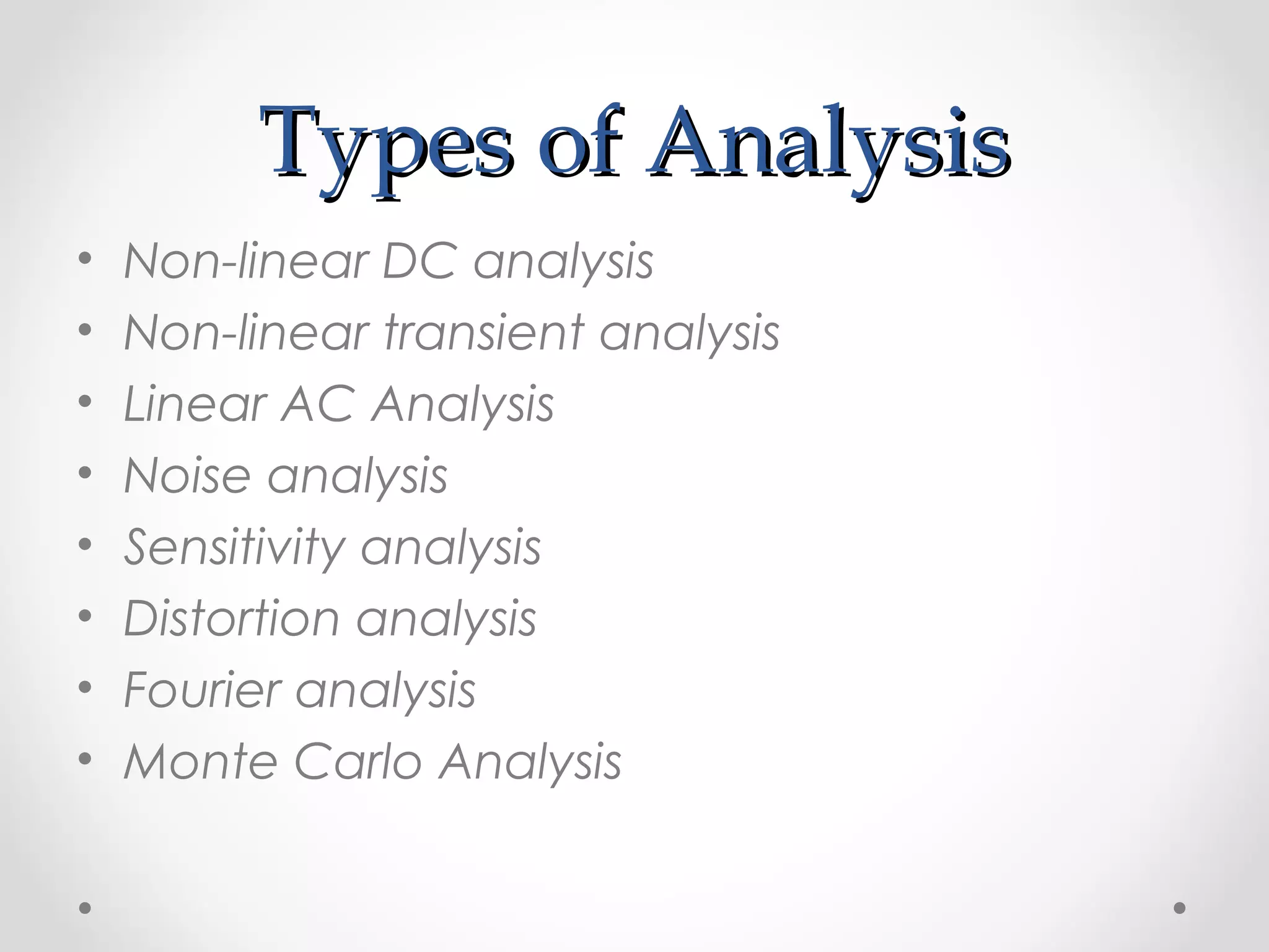
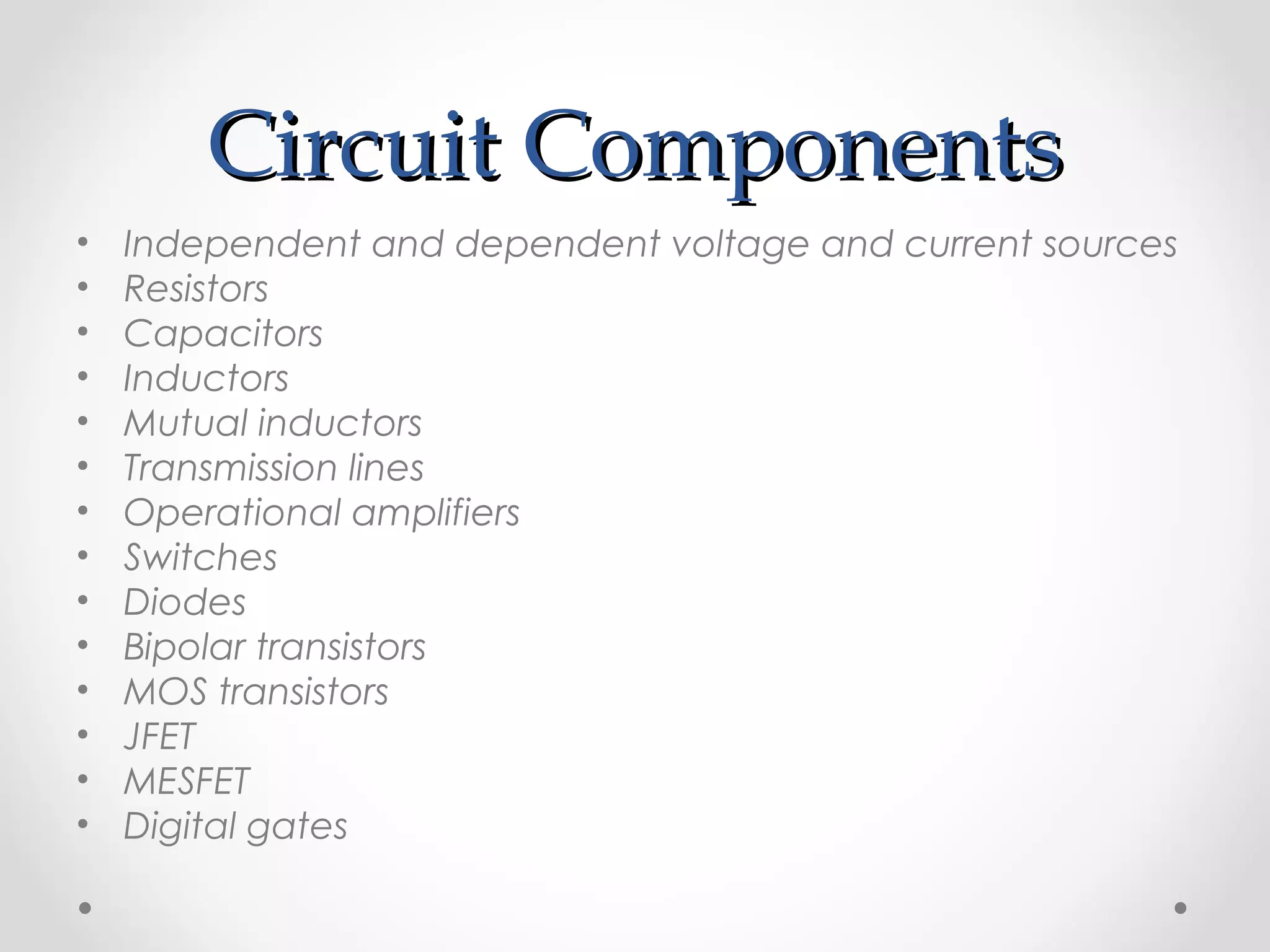
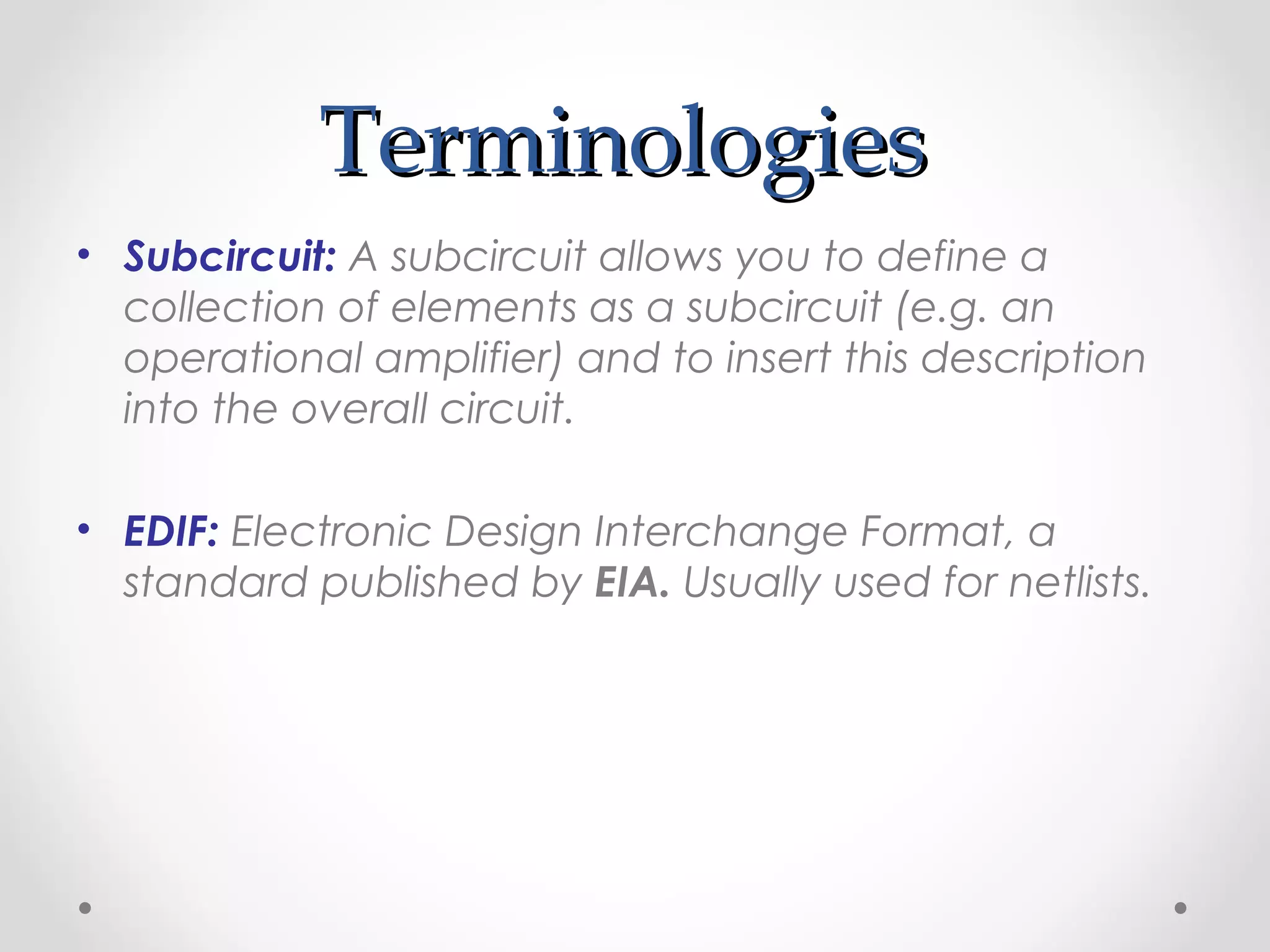
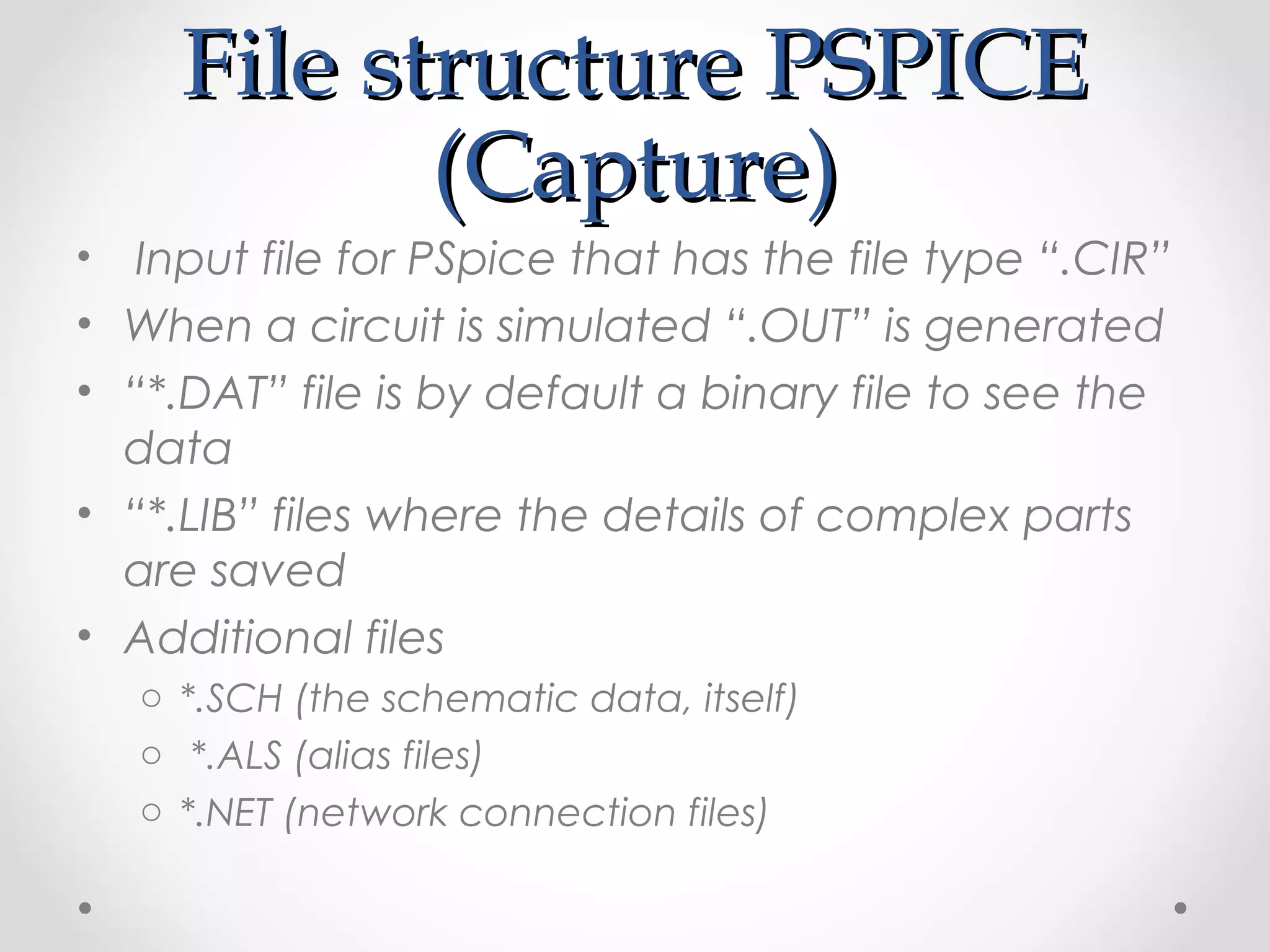
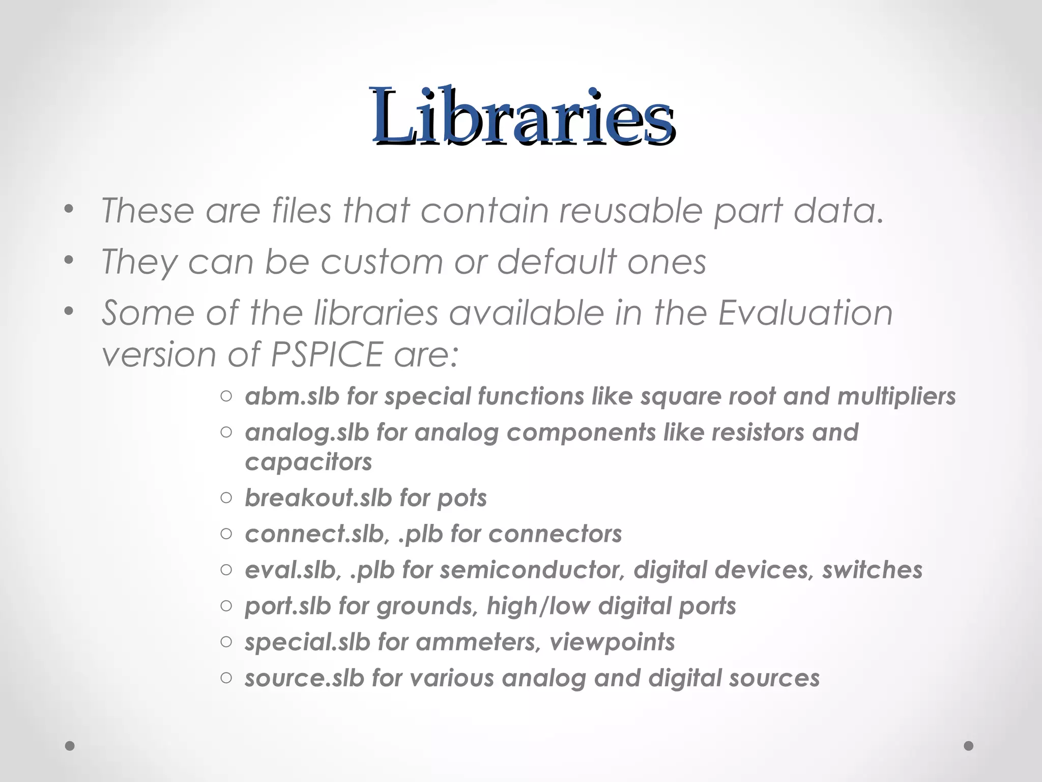
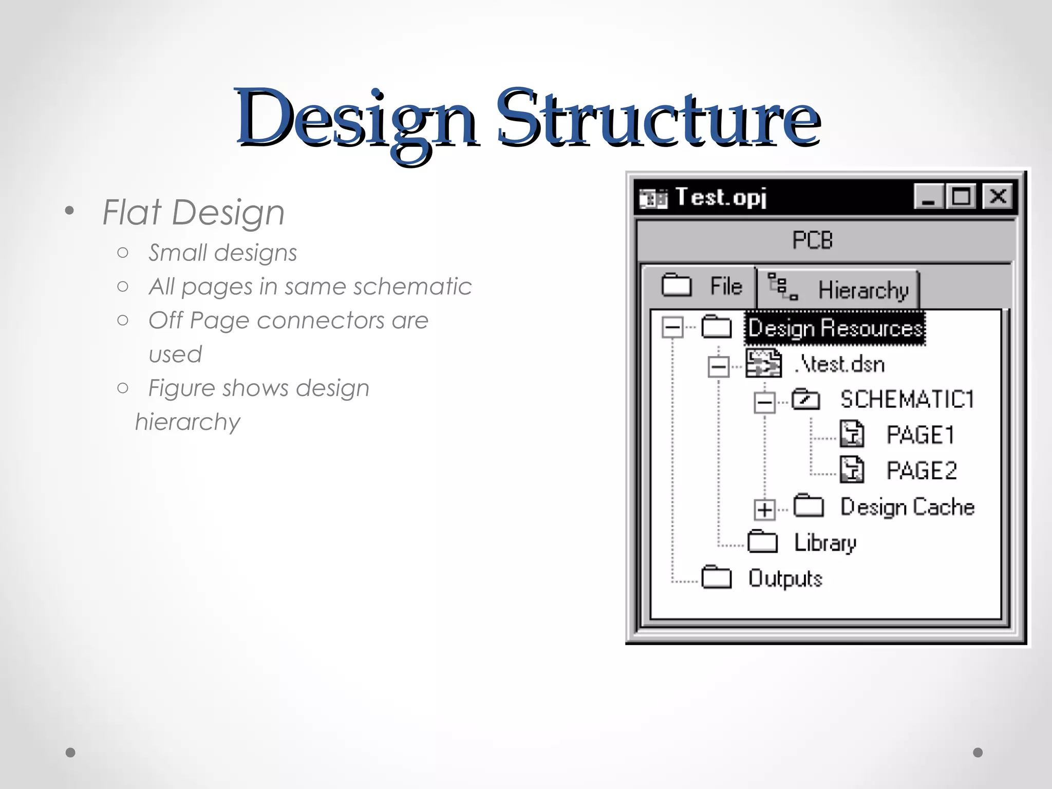
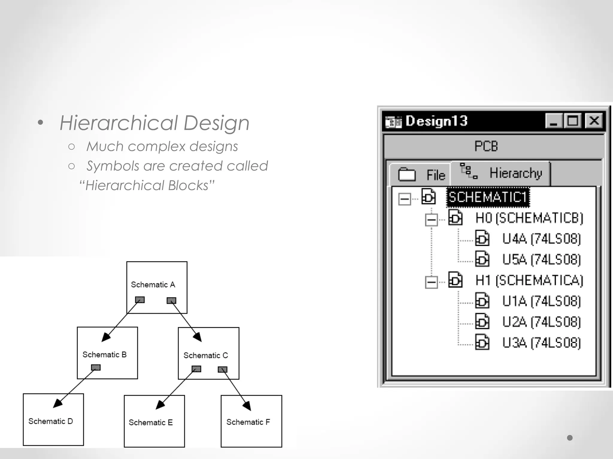
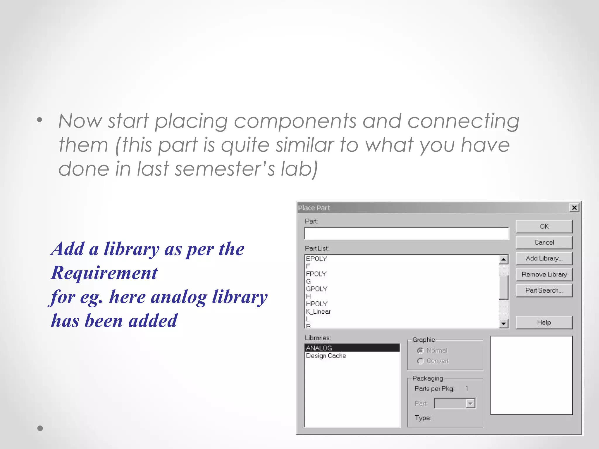
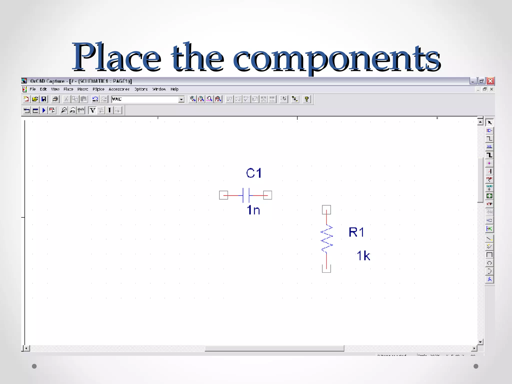
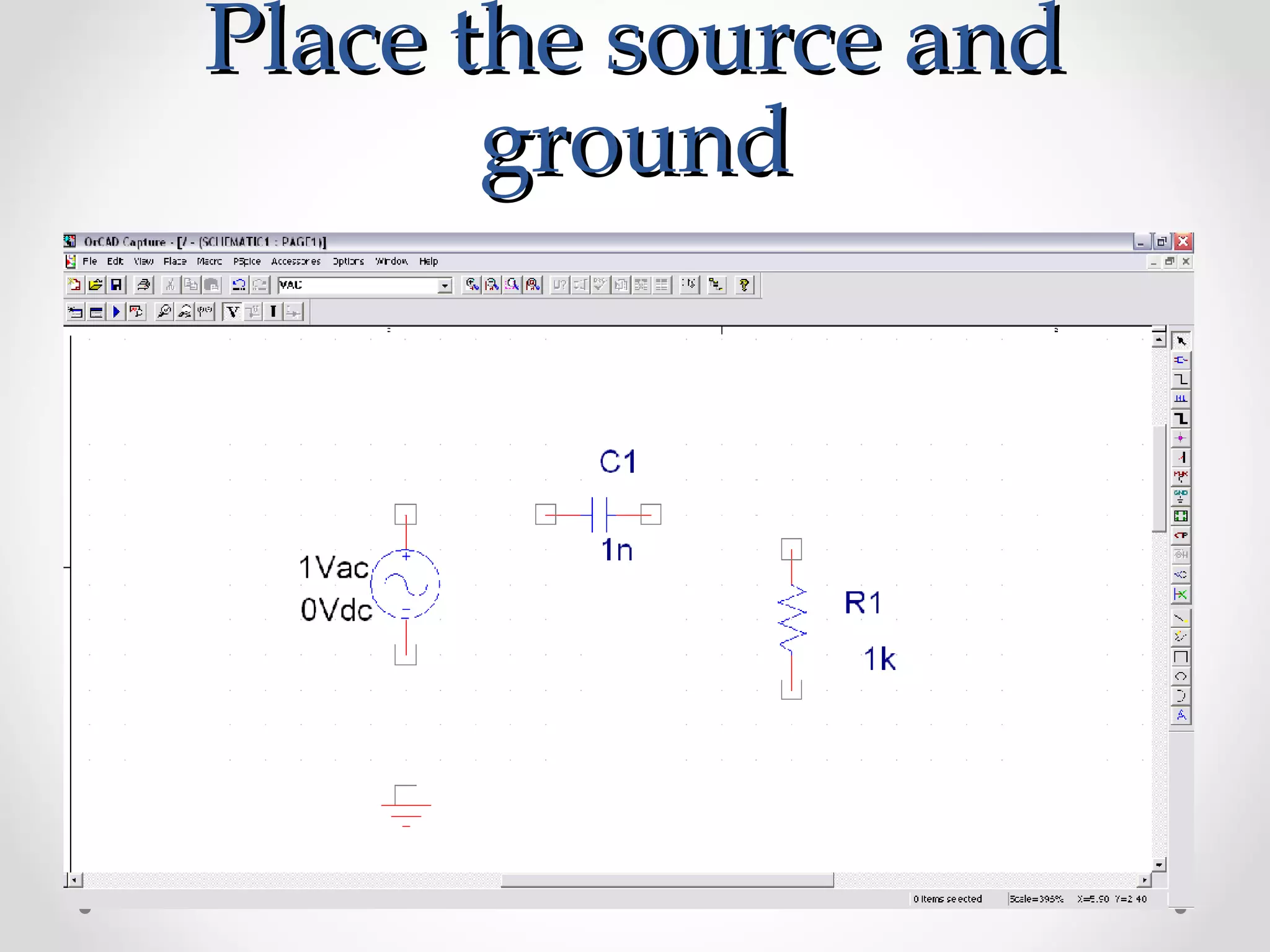
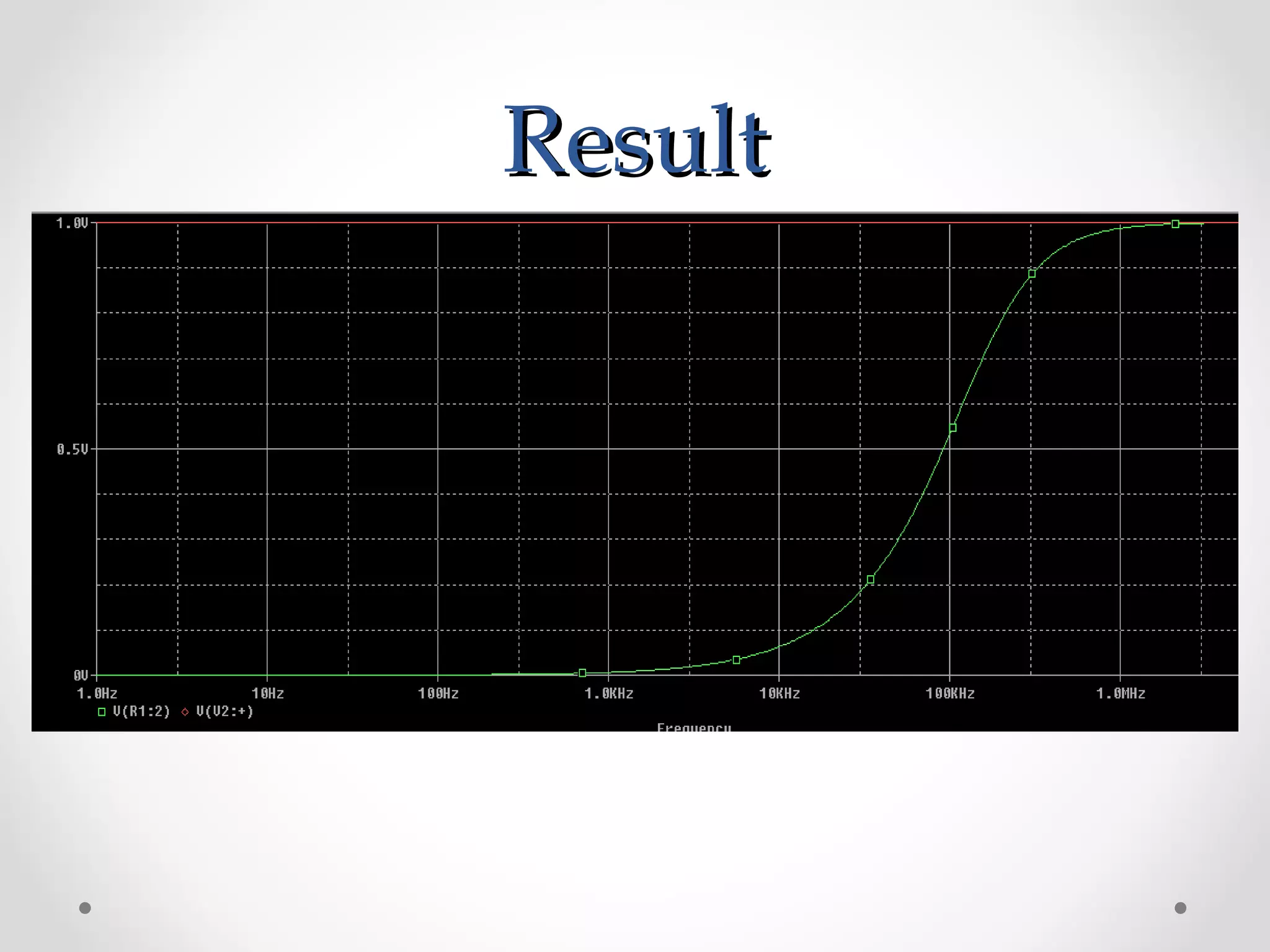
Basics of PSPICE.
SPICE (Simulation Program for Integrated Circuits Emphasis) is a general purpose analog circuit simulator that is used to verify circuit designs and to predict the circuit behavior.
PSpice is a PC version of SPICE and HSpice is a version that runs on workstations and larger computers
2. IndexIndex
1. Introduction
2. Types of analysis
3. Circuit components
4. File structures
5. Libraries
6. Parts
7. Design structure
8. Design example
9. Results
10. Conclusion
3. IntroductionIntroduction
• SPICE (Simulation Program for Integrated Circuits
Emphasis) is a general purpose analog circuit
simulator that is used to verify circuit designs and to
predict the circuit behavior.
• PSpice is a PC version of SPICE and HSpice is a
version that runs on workstations and larger
computers.
• PSpice has analog and digital libraries of
standard components (such as NAND, NOR,
flip-flops, and other digital gates, op amps, etc)
which makes it a useful tool for a wide range of
analog and digital applications.
4. Types of AnalysisTypes of Analysis
• Non-linear DC analysis
• Non-linear transient analysis
• Linear AC Analysis
• Noise analysis
• Sensitivity analysis
• Distortion analysis
• Fourier analysis
• Monte Carlo Analysis
5. Circuit ComponentsCircuit Components
• Independent and dependent voltage and current sources
• Resistors
• Capacitors
• Inductors
• Mutual inductors
• Transmission lines
• Operational amplifiers
• Switches
• Diodes
• Bipolar transistors
• MOS transistors
• JFET
• MESFET
• Digital gates
6. TerminologiesTerminologies
• Subcircuit: A subcircuit allows you to define a
collection of elements as a subcircuit (e.g. an
operational amplifier) and to insert this description
into the overall circuit.
• EDIF: Electronic Design Interchange Format, a
standard published by EIA. Usually used for netlists.
7. File structure PSPICEFile structure PSPICE
(Capture)(Capture)
• Input file for PSpice that has the file type “.CIR”
• When a circuit is simulated “.OUT” is generated
• “*.DAT” file is by default a binary file to see the
data
• “*.LIB” files where the details of complex parts
are saved
• Additional files
o *.SCH (the schematic data, itself)
o *.ALS (alias files)
o *.NET (network connection files)
8. LibrariesLibraries
• These are files that contain reusable part data.
• They can be custom or default ones
• Some of the libraries available in the Evaluation
version of PSPICE are:
o abm.slb for special functions like square root and multipliers
o analog.slb for analog components like resistors and
capacitors
o breakout.slb for pots
o connect.slb, .plb for connectors
o eval.slb, .plb for semiconductor, digital devices, switches
o port.slb for grounds, high/low digital ports
o special.slb for ammeters, viewpoints
o source.slb for various analog and digital sources
9. PartsParts
• Part is a basic building block which may represent
o One or more physical element
o Function
o Simulation model
o When a part is placed for first time its entry is done in “Design Cache”
What is “Design Cache”????... Go and Find Out Yourself
10. Design StructureDesign Structure
• Flat Design
o Small designs
o All pages in same schematic
o Off Page connectors are
used
o Figure shows design
hierarchy
11. • Hierarchical Design
o Much complex designs
o Symbols are created called
“Hierarchical Blocks”
12. Things to remember beforeThings to remember before
startingstarting
• PSpice is not case sensitive
• All element names must be unique
• There must be a node designated "0" (Zero). This is
the reference node against which all voltages are
calculated.
• If any change is made in circuit make sure you
create netlist again before simulating it.
13. Getting StartedGetting Started
• File New Project Analog or Mixed A/D
Make sure to choose Analog or Mixed A/D and proper
location for project
14. • Next comes following window
Make sure you select “Create a blank project”
15. • This is how a typical “Schematic” Window will look
like
16. • Now start placing components and connecting
them (this part is quite similar to what you have
done in last semester’s lab)
Add a library as per the
Requirement
for eg. here analog library
has been added
17. • After completing the circuit save it and run it.
• Plot appropriate waveform by probing on circuit.
18. Design ExampleDesign Example
• Take example of a high pass filter (RC)
• First we will follow initial steps of creating a new
project
• Now placing the components.
26. ConclusionConclusion
• Thus we have learn the basics of P-Spice software
and it’s functioning theoretically.
• Its easy and simple software for simulations and
analysis of the circuits.