This lab report summarizes an experiment configuring VLANs (Virtual Local Area Networks) on a network switch. The report describes:
1) Configuring two VLANs (named "HR" and "IT") on the switch to isolate two networks and prevent communication between PCs in different VLANs.
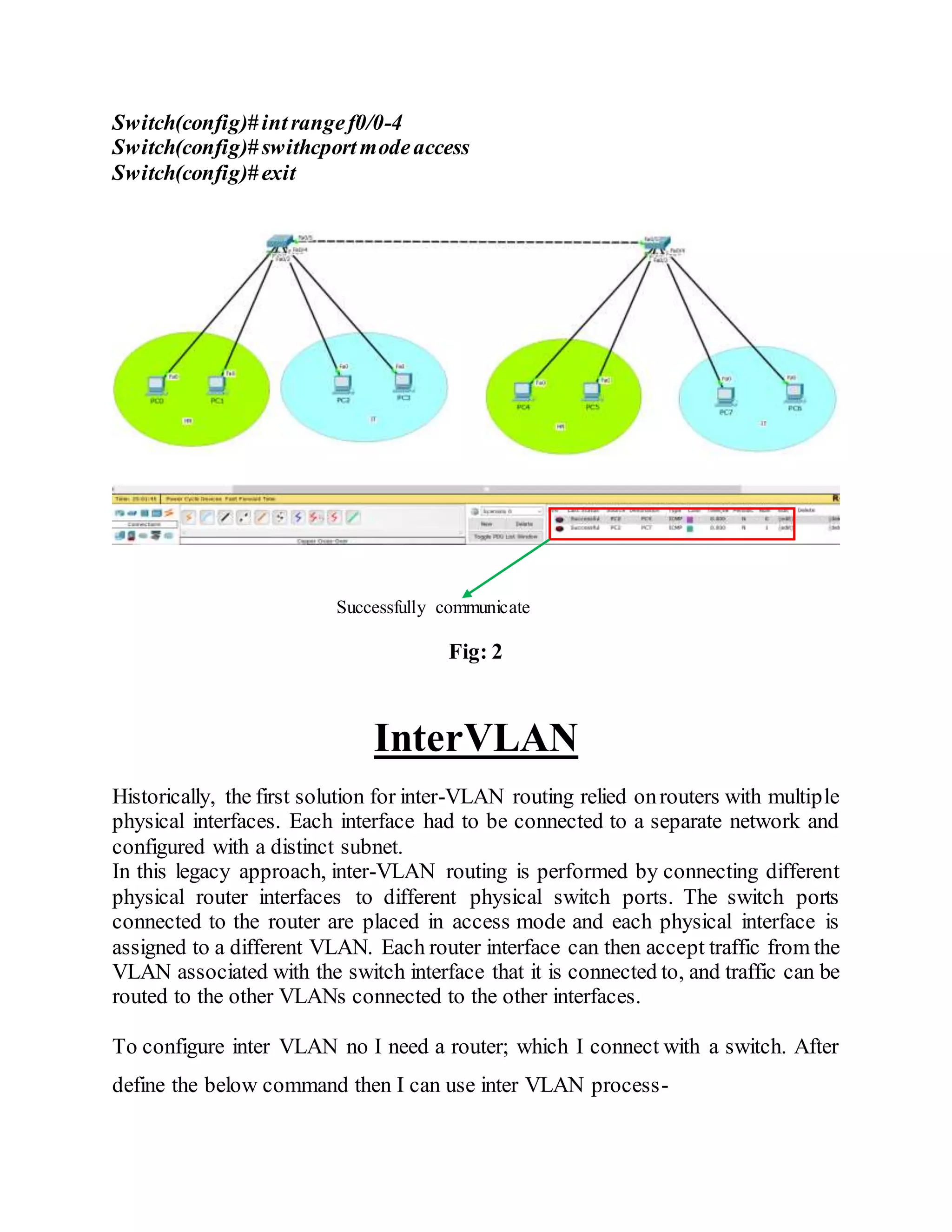
2) Connecting two switches with a crossover cable and configuring trunk mode to allow communication between PCs in the same VLAN but different switches.
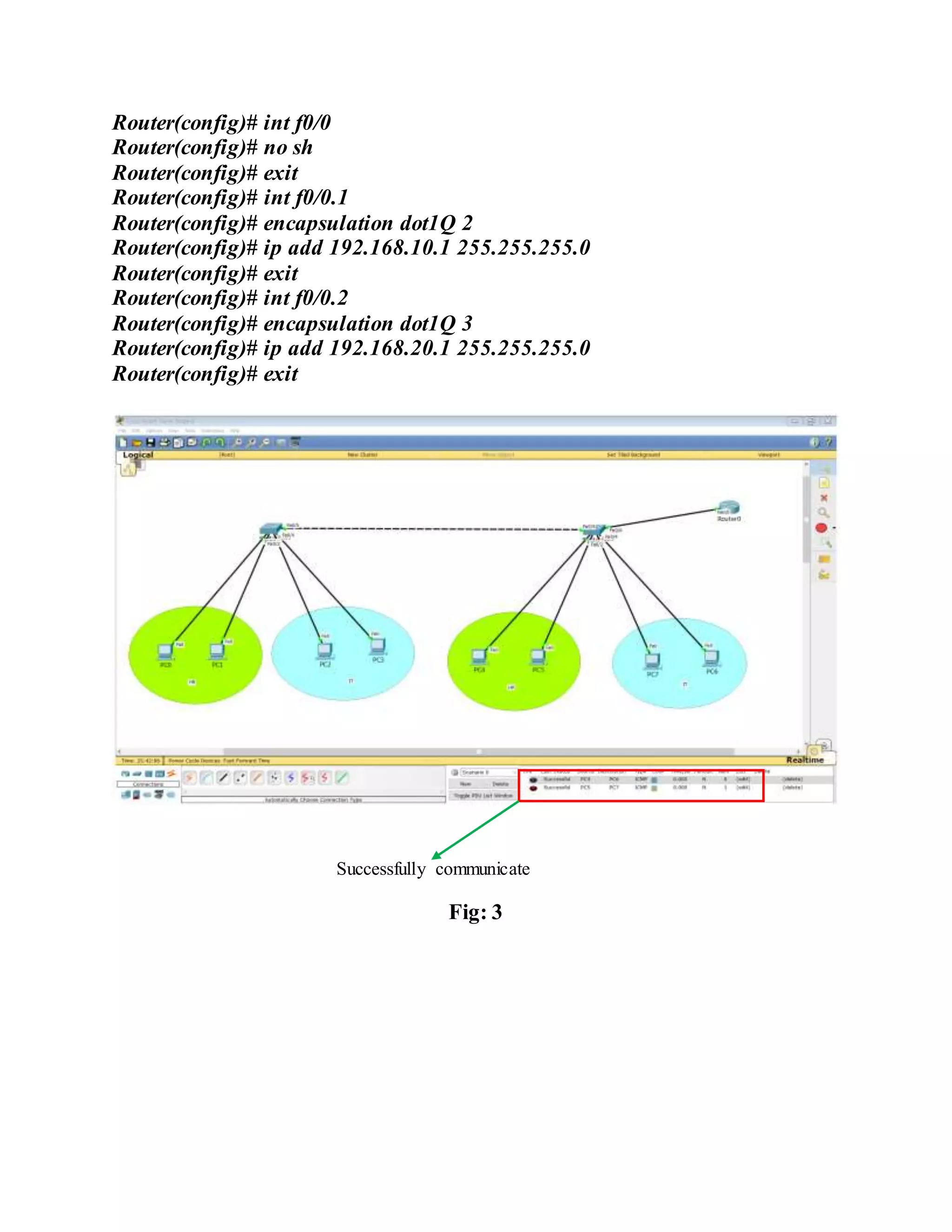
3) Using a router connected to the switch with subinterfaces for each VLAN to enable inter-VLAN communication and routing between the isolated networks.

![ExperimentNo- 03
ExperimentName: Configuration VLAN(Virtual Local Area Network).
Objective:
To learn about the configuration of VLAN (Virtual Local Area Network).
VLAN:
A virtual LAN (VLAN) is any broadcastdomain that is partitioned and isolated in
a computer network at the data link layer (OSI layer 2).[1][2] LAN is the abbreviation
for local area network and in this context virtual refers to a physical object recreated
and altered by additional logic. VLANs work by applying tags to network frames
and handling these tags in networking systems – creating the appearance and
functionality of network traffic that is physically on a single network but acts as if it
is split between separate networks. In this way, VLANs can keep network
applications separate despite being connected to the same physical network, and
without requiring multiple sets of cabling and networking devices to be deployed.
VLAN Configuration:
To configure the VLAN first of all I arrange two network in a switch where each
network have two connected PC. Then I isolate two network by define the VLAN
as follow below-
Switch# configureterminal
Switch(config)#vlan2
Switch(config-vlan)# nameHR
Switch(config-vlan)# exit
Switch(config)#vlan3
Switch(config-vlan)# nameHR
Switch(config-vlan)# exit
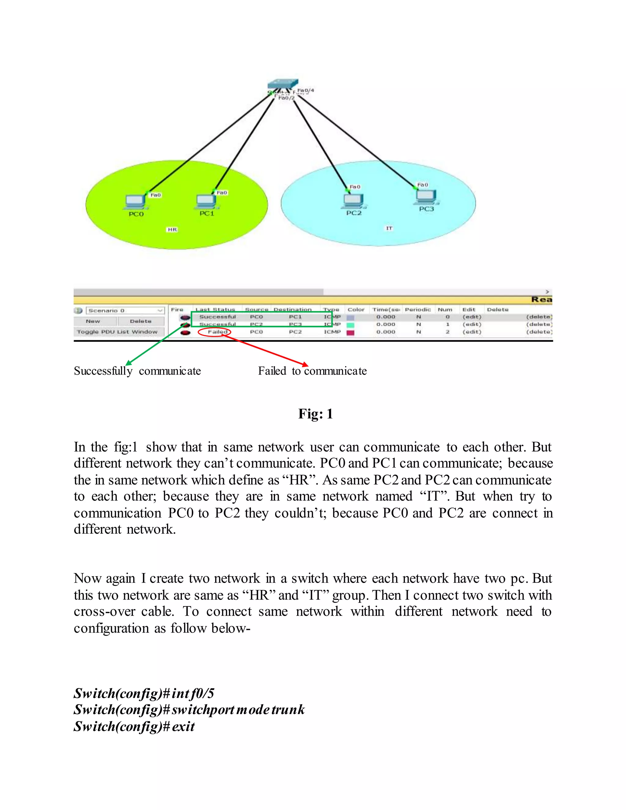
After configuration VLAN two network now isolated. Therefore, they can’t
communicate to each other. The below fig is showed it clearly-](https://image.slidesharecdn.com/virtuallocalareanetworkvlan-190928083644/75/Virtual-local-area-network-VLAN-2-2048.jpg)