Download to read offline

![Dr.Y.NARASIMHA MURTHY Ph.D
yayavaram@yahoo.com
9
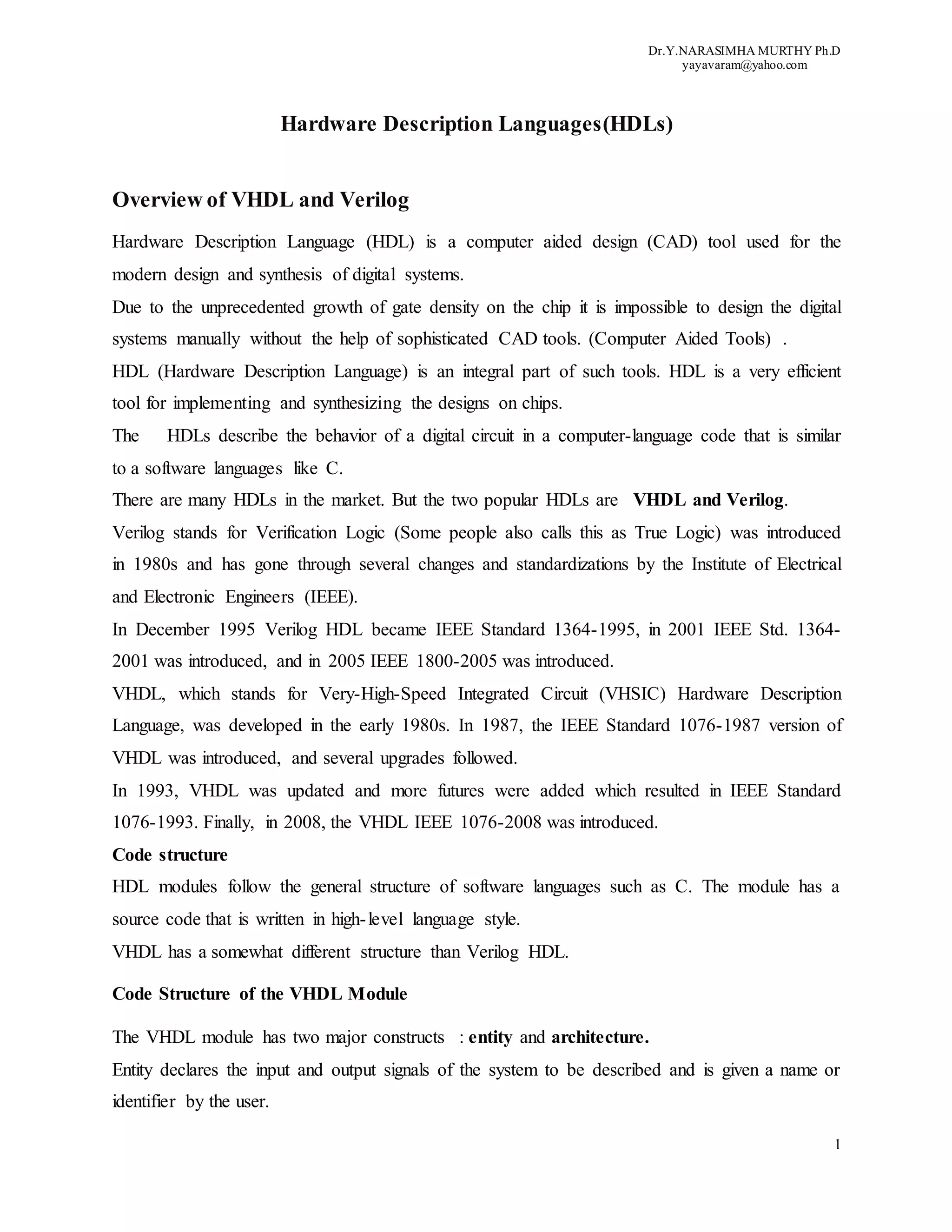
A is compared to B. If A is equal to B, the value of the expression (A = B) is true (1); otherwise,
it is false (0).
If (A < B) then
If A is less than B, the value of the expression (A < B) is true (1); otherwise, it is false (0).
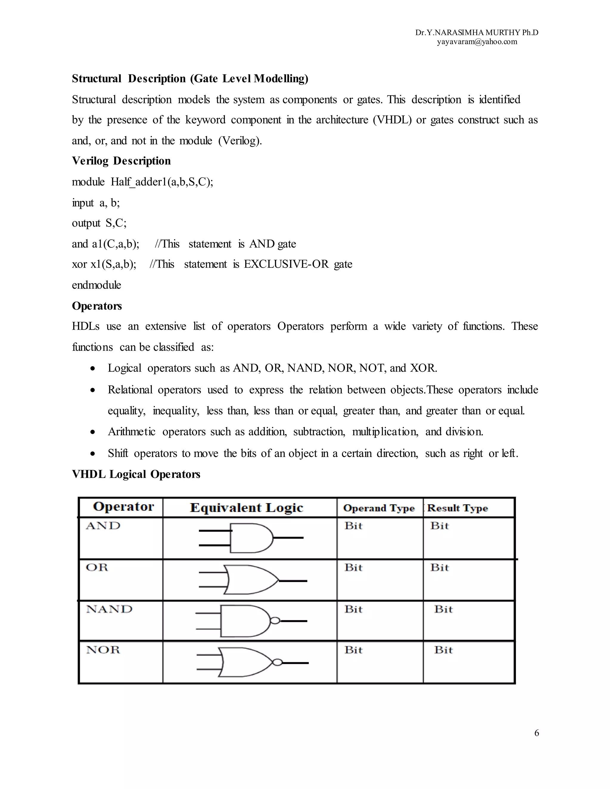
Verilog Relational Operators
Verilog has a set of relational operators similar to VHDL. Similar to VHDL, the relational
operators return Boolean values: false (0) or true (1).
The relational operators are, less-than (<), more-than (>), less-than-or-equal-to (<=) and more-
than-or-equal-to (>=).In this case if any operand is unknown the whole expression evaluates to
unknown.
For the conditional operator “?” the format is:
Conditional- expression? true- expression: false-expression ;
The conditional expression is evaluated; if true, true-expression is executed If false, false-
expression is executed. If the result of the conditional expression is “x,” both false and true are
executed, and their results are compared bit by bit; if two corresponding bits are the same, the
common value of these bits is returned. If they are not equal, an “x” is returned.
Ex: Relational Operators
module relational_ operators;
reg [3:0] a, b ,c, d;
initial begin
a=2;
b=5;
c=2;](https://image.slidesharecdn.com/hdlsoverview-200618132059/75/OVERVIEW-OF-HARDWARE-DESCRIPTION-LANGUAGES-HDLs-9-2048.jpg)
![Dr.Y.NARASIMHA MURTHY Ph.D
yayavaram@yahoo.com
14
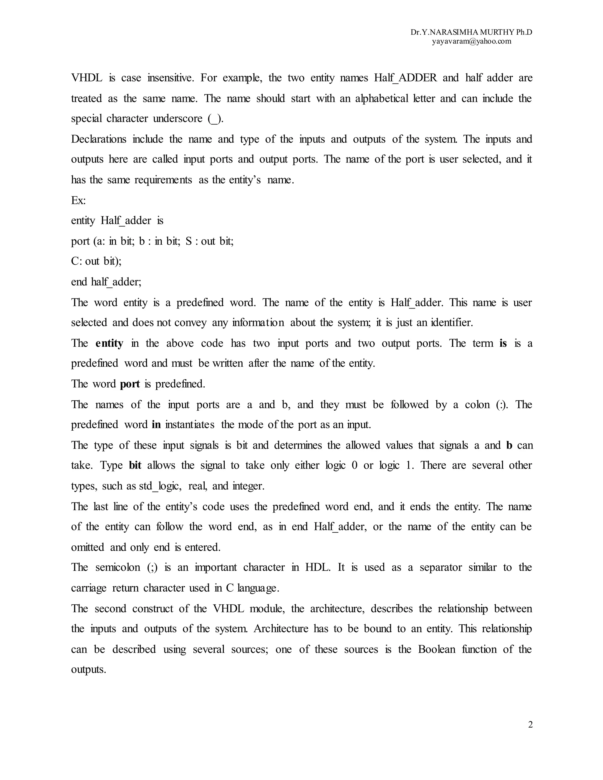
The Verilog shift operators are shift-left (<<) and shift-right (>>). The shift operator takes a
vector and a number indicating the shift. The empty bits caused by shifting are filled with zeros
Ex:
module shift_operators;
reg [7:0] a;
initial begin
a = 8'b10101010;
$displayb(a << 1); // shift left by 1, evaluates to // 8'b01010100
$displayb(a >> 2); // shift right by 2, evaluates to // 8'b01010101
end
endmodule // bitwise_operators
The shift operators are useful in modeling shift registers, long multiplication algorithms, etc.
Data Types
HDL is a hardware description Language used to describe the hardware of a system.So, the data
or operands used in the language must have several types to match the need for describing the
hardware. For example, if we are describing a signal, we need to specify its type (i.e., the values
that the signal can take), such as type bit, which means that the signal can assume only 0 or 1, or
type std_logic, in which the signal can assume a value out of nine possible values that include 0,
1, and high impedance.
VHDL Data Types
VHDL is a type-oriented language; many operations will not be executed if the right type for the
operands has not been chosen. The type of any element or object in VHDL determines the
allowed values that element can assume. Objects in VHDL can be signal, variable or constant.
VHDL data types can be classified into five groups depending on the nature of the values the
object can assume: scalar, composite, access, file, and other.
Scalar Types
The values that a scalar can assume are numeric. Numeric values can be integer, real, physical
(such as time), Boolean (0 or 1), or characters when stored as American Standard Code for
Information Interchange (ASCII) or compatible code.](https://image.slidesharecdn.com/hdlsoverview-200618132059/75/OVERVIEW-OF-HARDWARE-DESCRIPTION-LANGUAGES-HDLs-14-2048.jpg)
![Dr.Y.NARASIMHA MURTHY Ph.D
yayavaram@yahoo.com
18
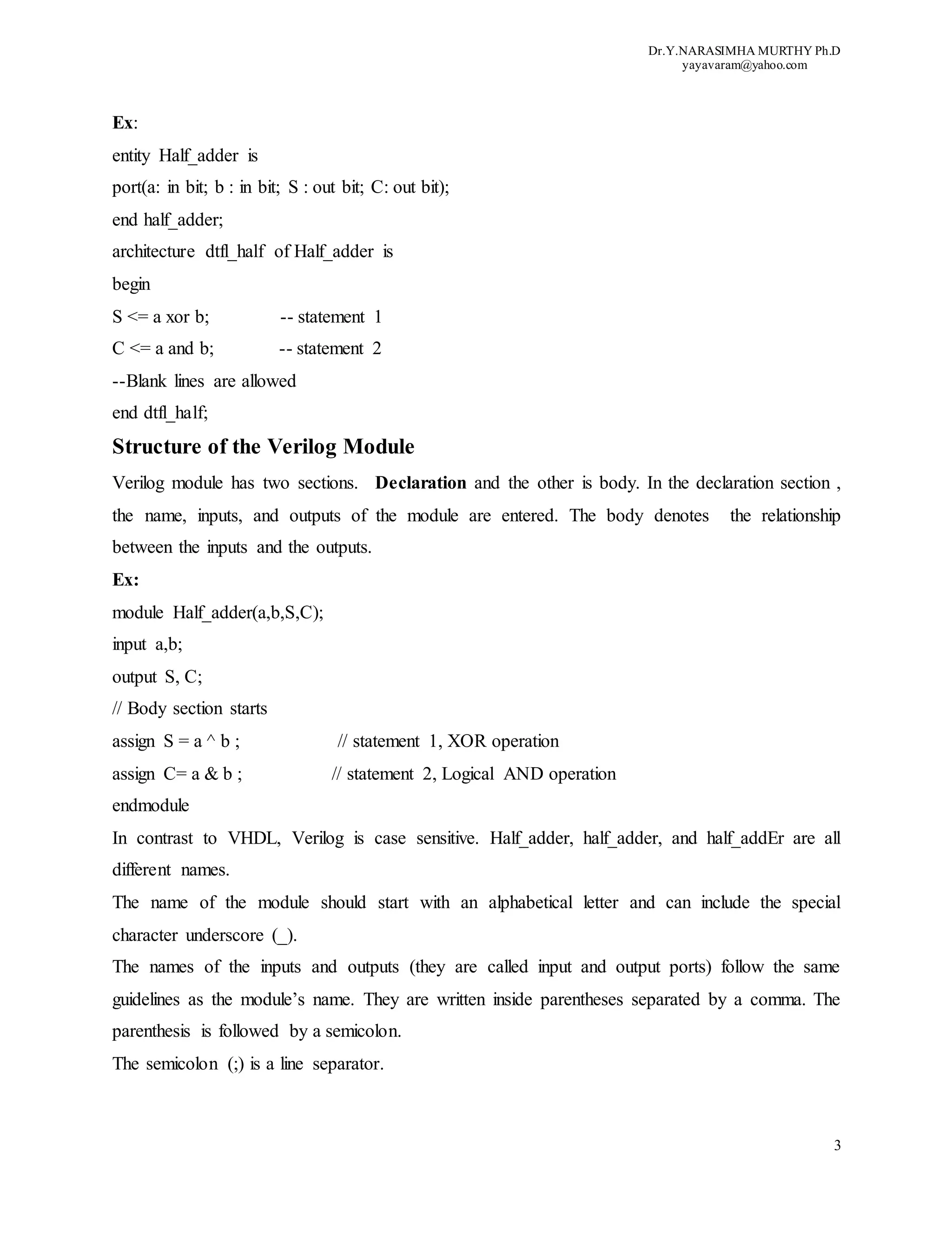
Examples of net types are wire sum;
wire S1 = 1’b0;
The first statement declares a net by the name sum. The second statement declares a net by the
name of S1; its initial value is 1’b0, which represents 1 bit with value 0.
Register
Register, in contrast to nets, stores values until they are updated. Register, as its name suggests,
represents data-storage elements. Register is declared by the predefined word reg.
Verilog supports four values for register
An example of register is:
reg Sum_total;
The above statement declares a register by the name Sum_total.
Vectors
Vectors are multiple bits. A register or a net can be declared as a vector.
Vectors are declared by brackets [ ]. Examples of vectors are:
wire [3:0] a = 4’b1010;
reg [7:0] total = 8’d12;
The first statement declares a net a. It has four bits, and its initial value is 1010 (b stands for bit).
The second statement declares a register total. Its size is eight bits, and its value is decimal 12 (d
stands for decimal).
Integers
Integers are declared by the predefined word integer. An example of integer declaration is:
integer no_bits;
The above statement declares no_bits as an integer.
Real
Real (floating-point) numbers are declared with the predefined word real. Examples of real
values are 2.4, 56.3, and 5e12. The value 5e12 is equal to 5 × 10¹². The following statement
declares the register weight as real:](https://image.slidesharecdn.com/hdlsoverview-200618132059/75/OVERVIEW-OF-HARDWARE-DESCRIPTION-LANGUAGES-HDLs-18-2048.jpg)
![Dr.Y.NARASIMHA MURTHY Ph.D
yayavaram@yahoo.com
19
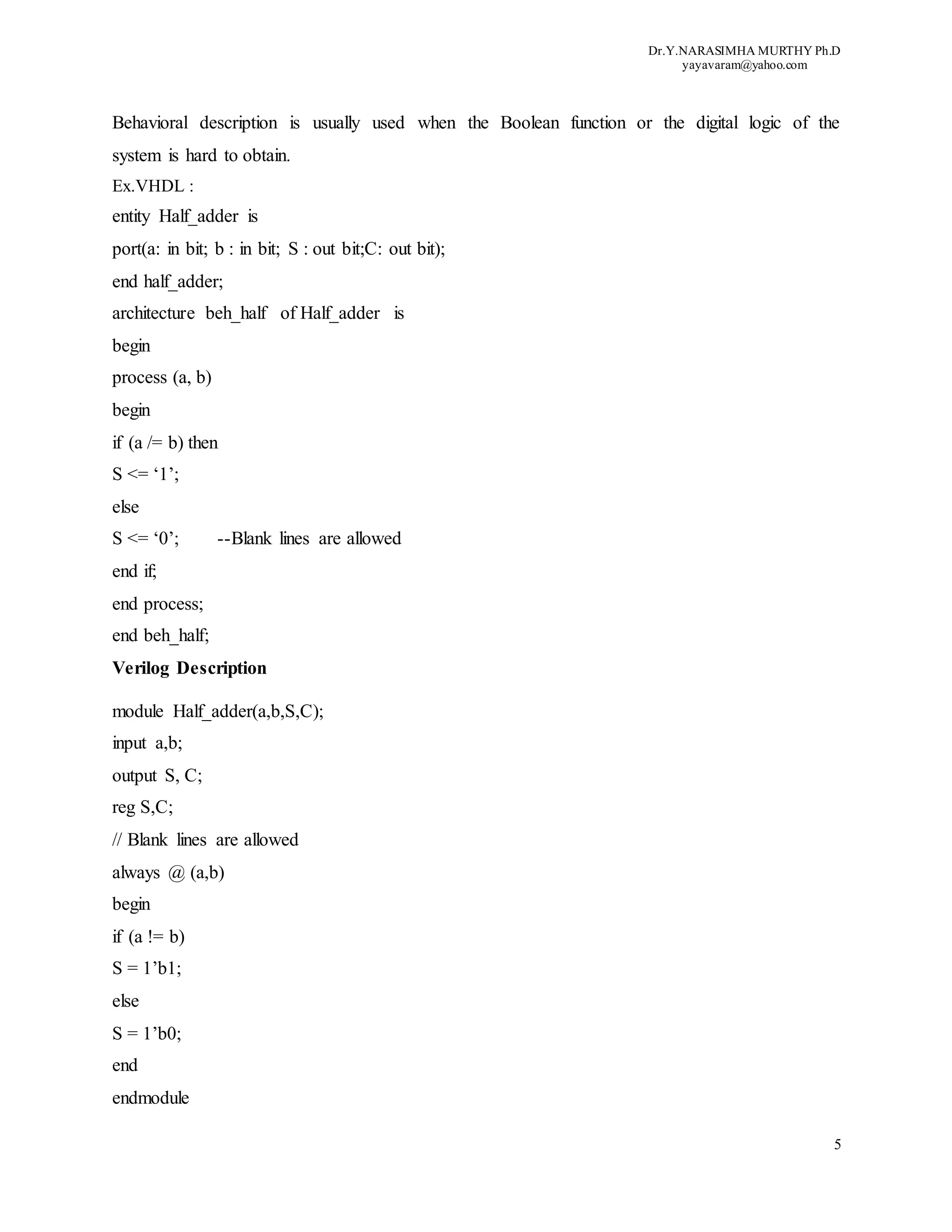
real weight;
Parameter
Parameter represents a global constant. It is declared by the predefined word parameter.
Ex:
module compr_genr (X, Y, xgty, xlty, xeqy);
parameter N = 3;
input [N:0] X, Y;
output xgty, xlty, xeqy;
wire [N:0] sum, Yb;
To change the size of the inputs x and y, the size of the nets sum, and
the size of net Yb to eight bits, the value of N is changed to seven as:
parameter N = 7
Arrays
Verilog, in contrast to VHDL, does not have a predefined word for array.
Registers and integers can be written as arrays.
Let us consider example
parameter N = 4;
parameter M = 3;
reg signed [M:0] carry [0:N];
The above statements declare an array by the name carry. The array carry has five elements, and
each element is four bits. The four bits are in two’s complement form. For example, if the value
of a certain element is 1001, then it is equivalent to decimal –7. Arrays can be multidimensional.
Differences between VHDL and Verilog.
The VHDL language describes a digital system as a set of entities while the Verilog language
describes a digital system as a set of modules
(ii) VHDL is a case insensitive while Verilog is case sensitive
(iii).VHDL is like Ada or Pascal programming language while Verilog is like C programming
language.
(iv).Verilog has compiler directives such as `timescale , `define , `ifdef, ifndef `else `elseif
`endif (conditional compiling), `include , etc. VHDL does not have compiler directives.](https://image.slidesharecdn.com/hdlsoverview-200618132059/75/OVERVIEW-OF-HARDWARE-DESCRIPTION-LANGUAGES-HDLs-19-2048.jpg)

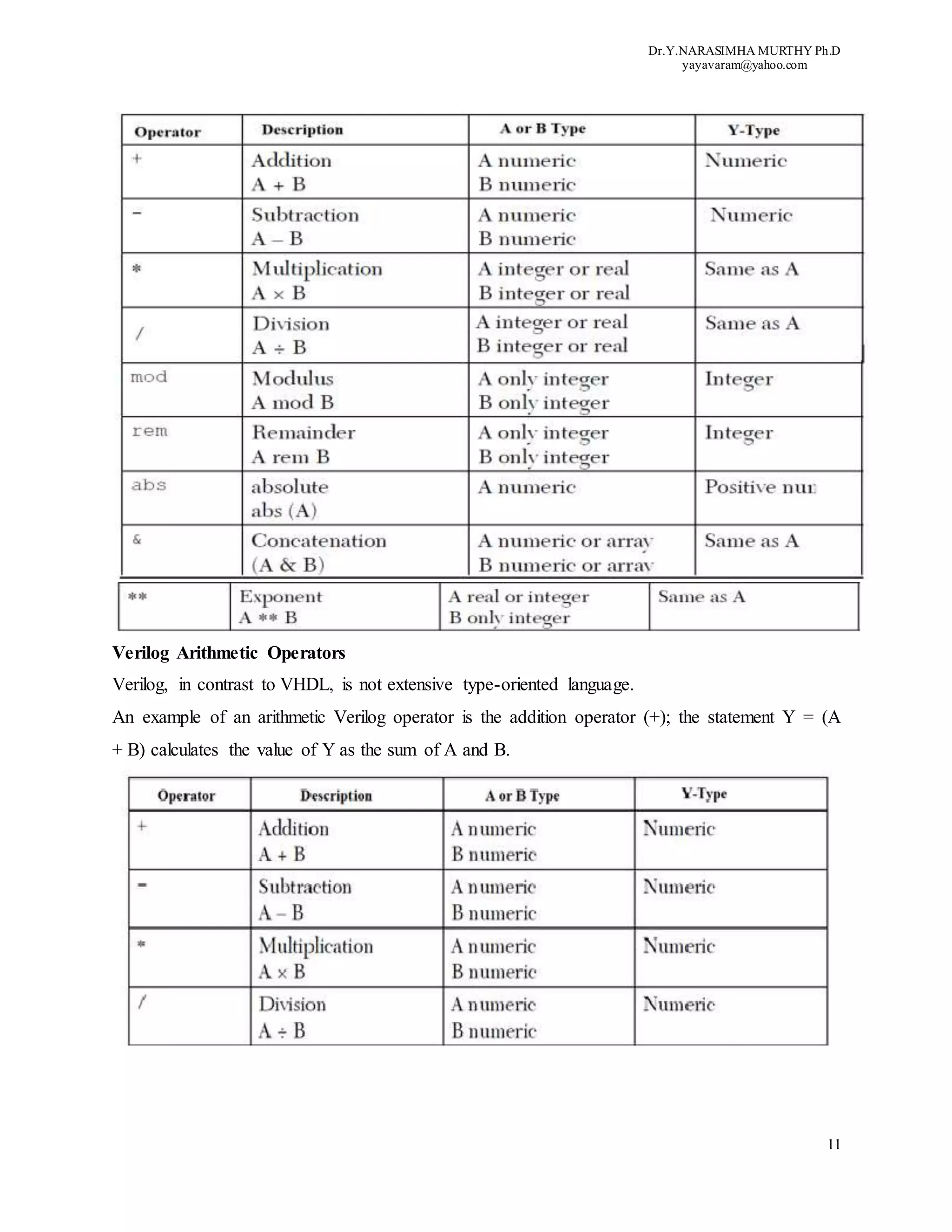
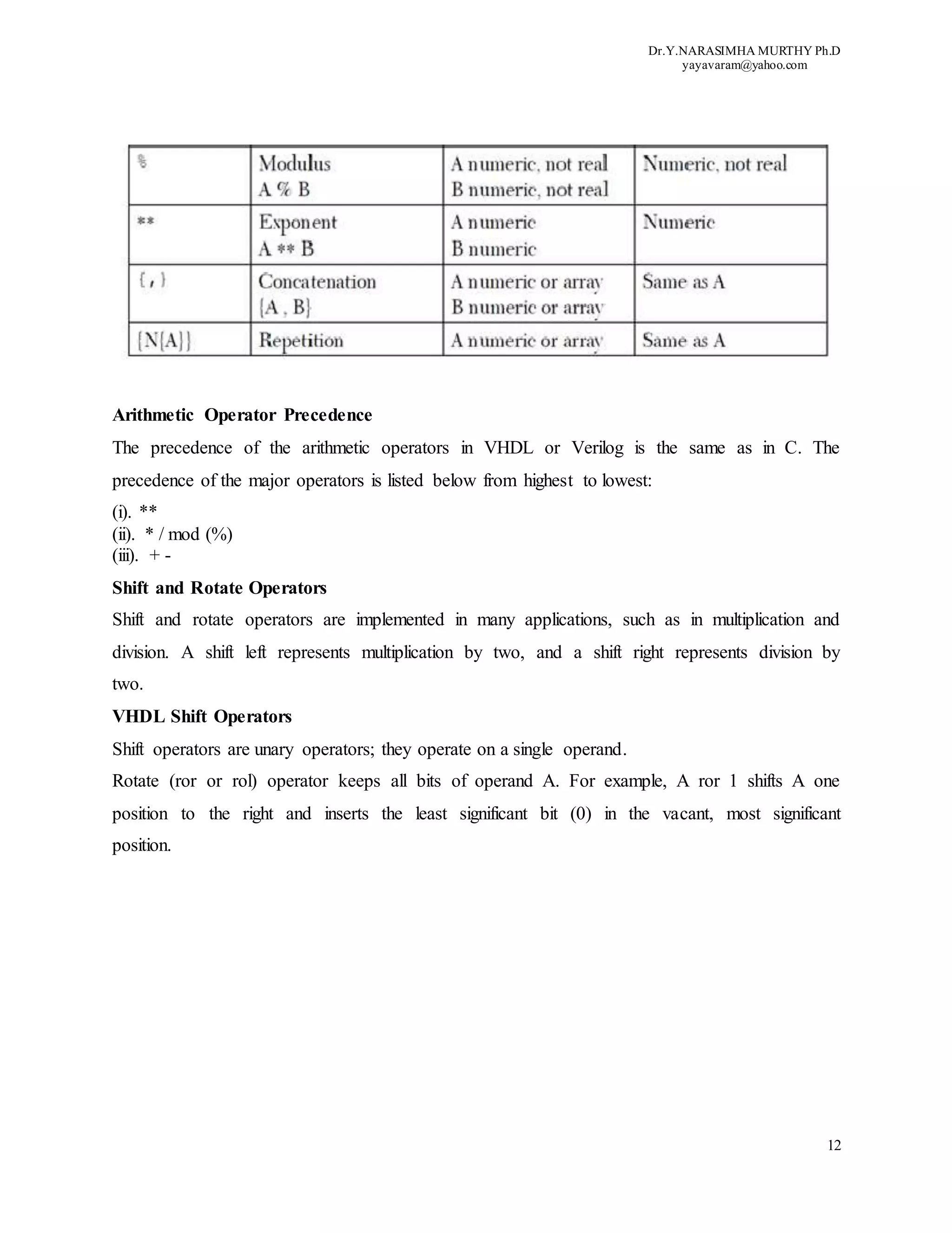
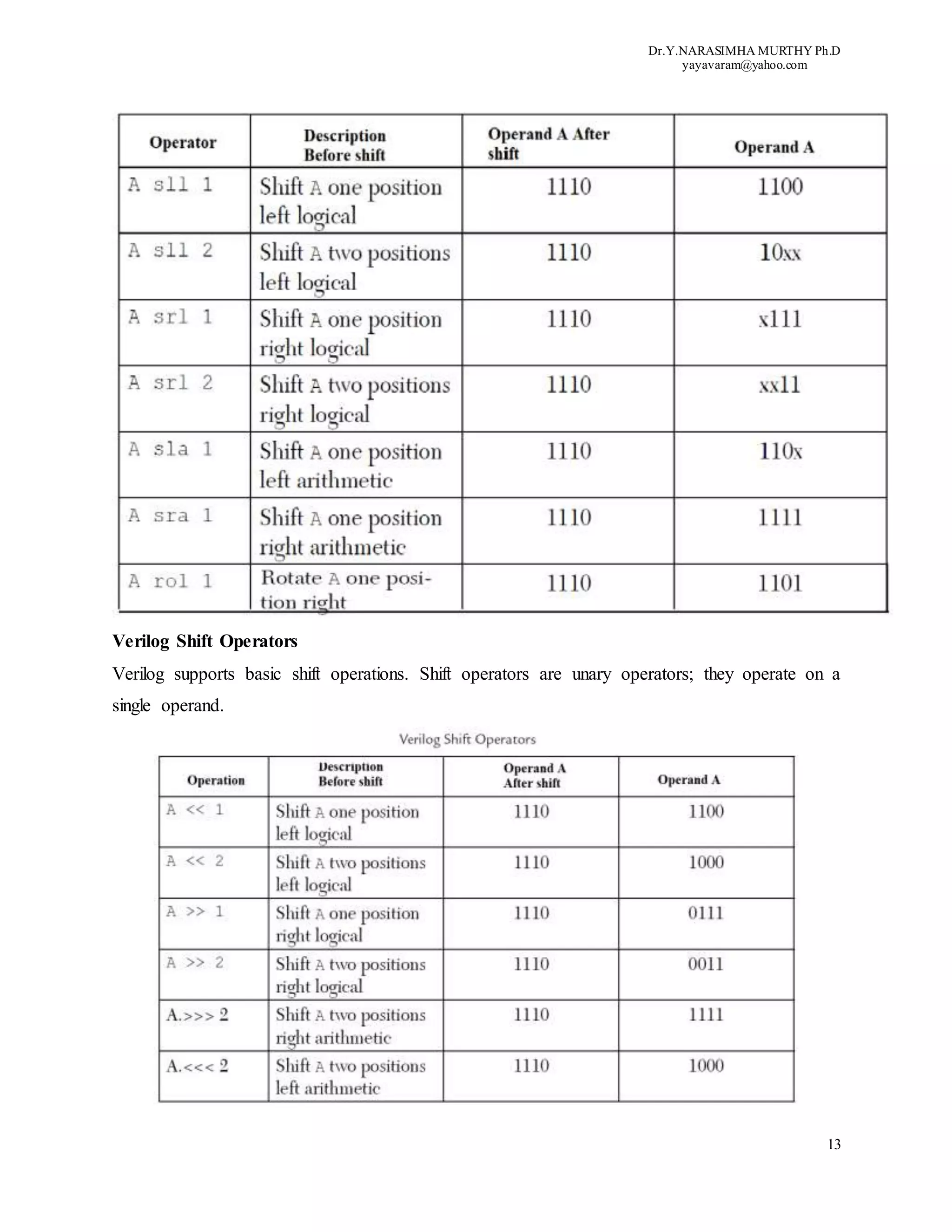
This document provides an overview of hardware description languages (HDLs) VHDL and Verilog. It discusses key aspects of HDLs including their structure, modeling approaches, operators, and data types. HDLs allow designing and synthesizing digital circuits using high-level language code. The two popular HDLs, VHDL and Verilog, have similar structures that describe a design's behavior and relationship between inputs and outputs. They support various modeling approaches and operator types to fully represent digital designs.


![Ece iv-fundamentals of hdl [10 ec45]-notes](https://cdn.slidesharecdn.com/ss_thumbnails/ece-iv-fundamentalsofhdl10ec45-notes-150103114952-conversion-gate02-thumbnail.jpg?width=640&height=640&fit=bounds)