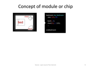
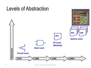
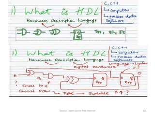
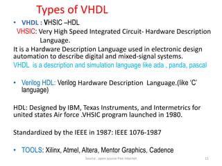
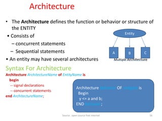
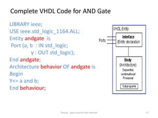
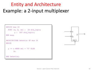
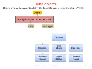
The document discusses VHDL (VHSIC Hardware Description Language) and provides information on various topics related to VHDL such as the design flow, levels of abstraction, types of HDLs, comparing VHDL and Verilog, simulation vs. synthesis, logic simulation, motivation for mixed-signal microelectronics, viewing designs by chip technology, concepts of modules and chips, levels of abstraction, types of VHDL, comparing VHDL and Verilog, choosing an HDL, the IEEE standard 1164, entities, architectures, and data objects in VHDL like constants, signals, and variables.
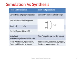
![CLASS: Each object belong to one of following class:
Constant: Hold values that cannot be changed within a
design.
Syntax: Constant constant name: Data Type := Value;
Example: 1] constant width: integer :=8;
2] constant Clk_Period: Time := 15 ns;
Continue 20
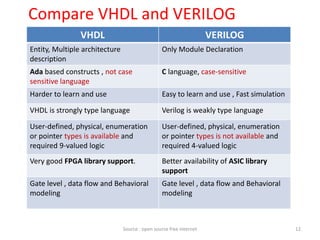
• Constant
• Signals
• Variables
Source : open source free internet](https://image.slidesharecdn.com/vhdl-201024071504/85/Vhdl-20-320.jpg)
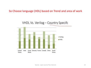
![CLASS
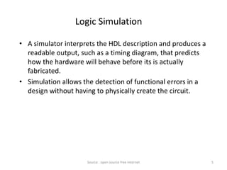
• Variable: A variable is an object with single value.
• Values can be change during simulation through the variable
assignment statements.
• A variable declaration include one or more identifiers.
• Variable used in Process not in architecture.
• Internal representation used by programmers; do not exist
physically.
• Syntax: variable identifier_list: type [range_expr] [:=expression];
Example: 1] variable A,B: Std_logic;
2] Variable sum : std_logic-vector( 0 to 7);
21
Variable name
Source : open source free internet](https://image.slidesharecdn.com/vhdl-201024071504/85/Vhdl-21-320.jpg)
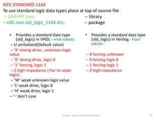
![CLASS
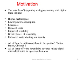
Signal: To represent wire connections within circuit.
Signal is an object within past history of values.
Signal have multiple drivers each with a current value and
projected future value. Signal Describing H/W sytsem.
Syntax: Signal identifier_list: type [range_expr] [:=expression];
Example: 1] signal count: STD_LOGIC_VECTOR (3 downto 0);
2] signal Gate-Delay: Time:=10ns;
-- count means 4 wires; they are count(3),count(2), count(1), count(0).
22Source : open source free internet](https://image.slidesharecdn.com/vhdl-201024071504/85/Vhdl-22-320.jpg)


![Ece iv-fundamentals of hdl [10 ec45]-notes](https://cdn.slidesharecdn.com/ss_thumbnails/ece-iv-fundamentalsofhdl10ec45-notes-150103114952-conversion-gate02-thumbnail.jpg?width=640&height=640&fit=bounds)


