This document describes a design for a speed bump that generates electricity from the kinetic energy of passing vehicles. It discusses two mechanisms - a spring coil mechanism and rack pinion mechanism - that use vehicles compressing the speed bump to power an electrical generator. The spring coil mechanism uses compressed air from the speed bump to power an air turbine connected to the generator. The design aims to reduce wasted energy from vehicles braking at speed bumps and provide a small amount of renewable energy.
In this document
Powered by AI
Introduction of the presentation by Jashobanti Biswal; outlines various mechanisms to generate electricity using vehicle weight.
Discusses energy waste at speed breakers and focuses on spring coil and rack-pinion mechanisms as effective methods for energy generation.
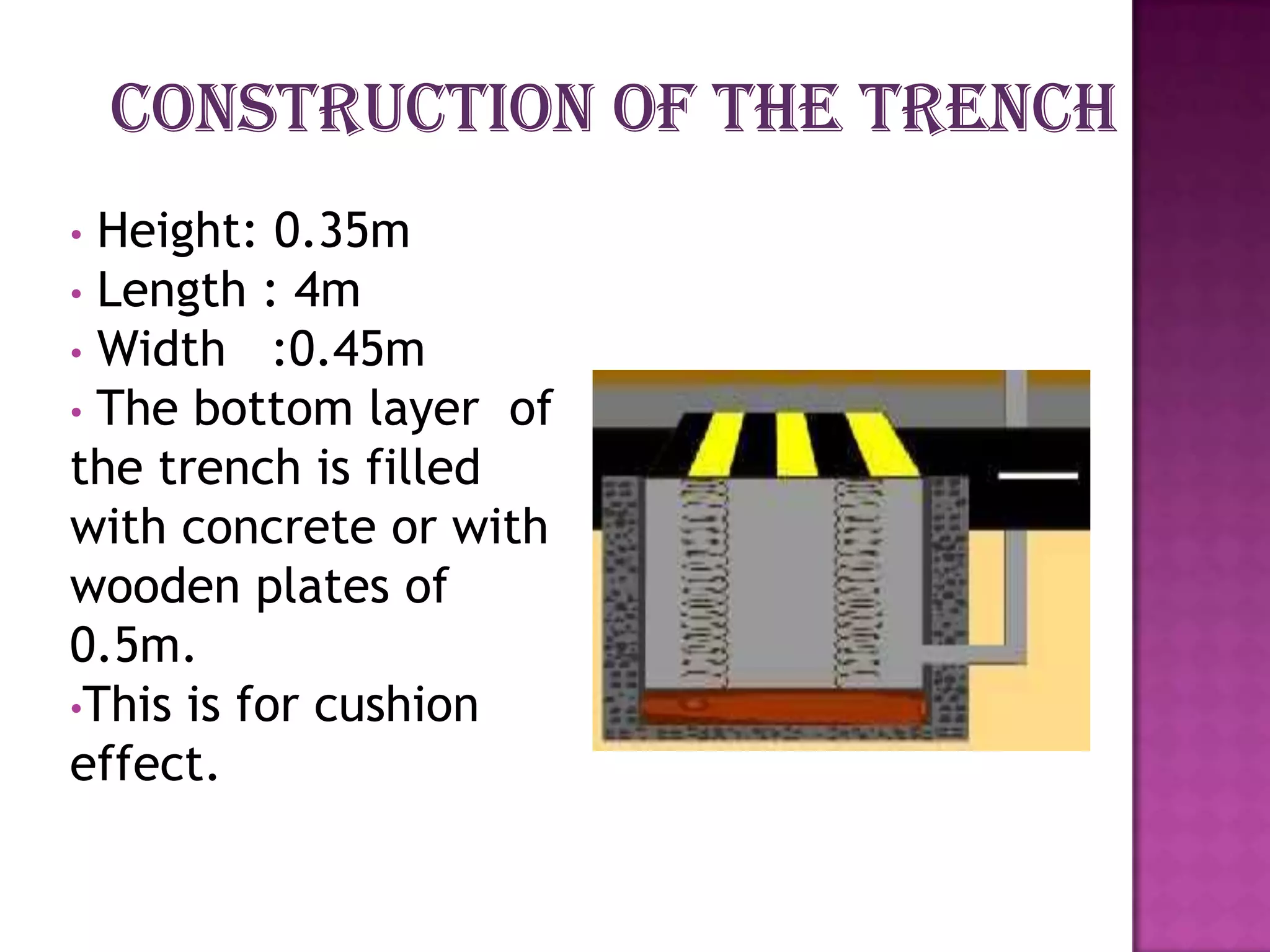
Details the working principle of converting mechanical energy to electrical energy, including spring specifications and dimensions.
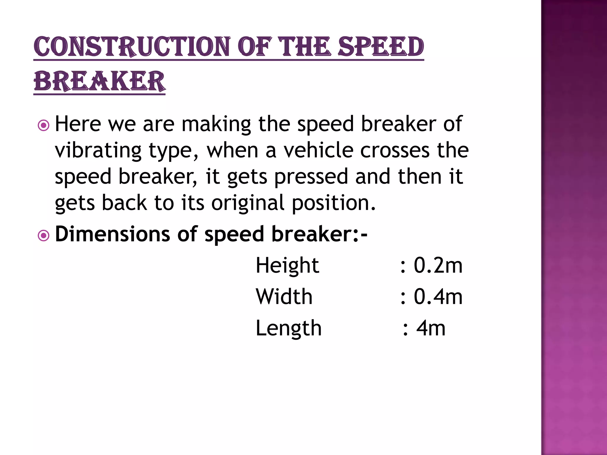
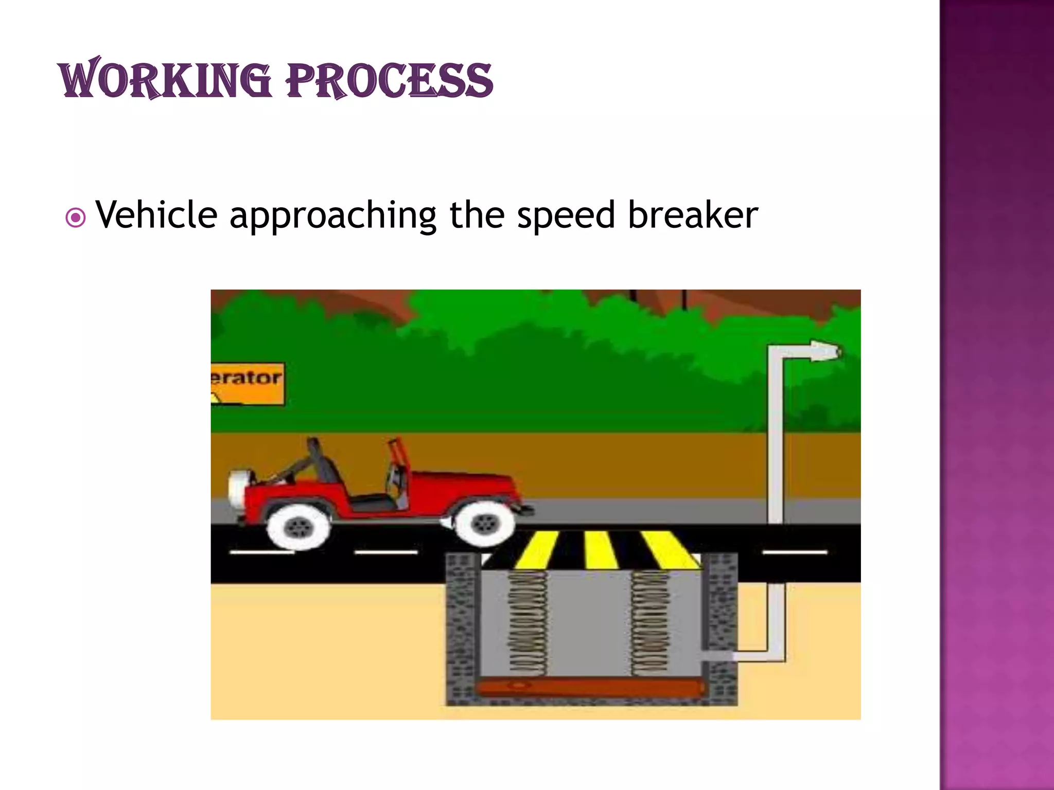
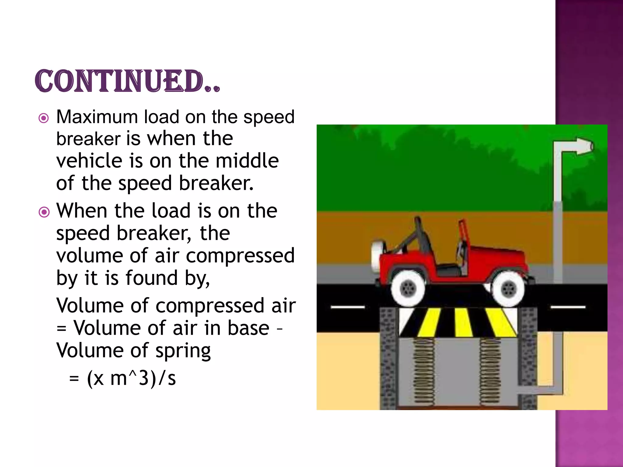
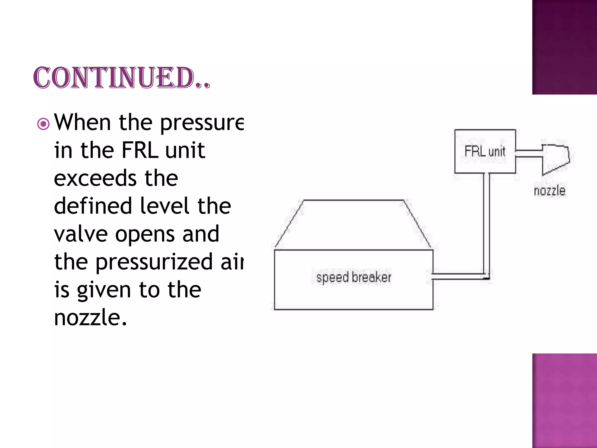
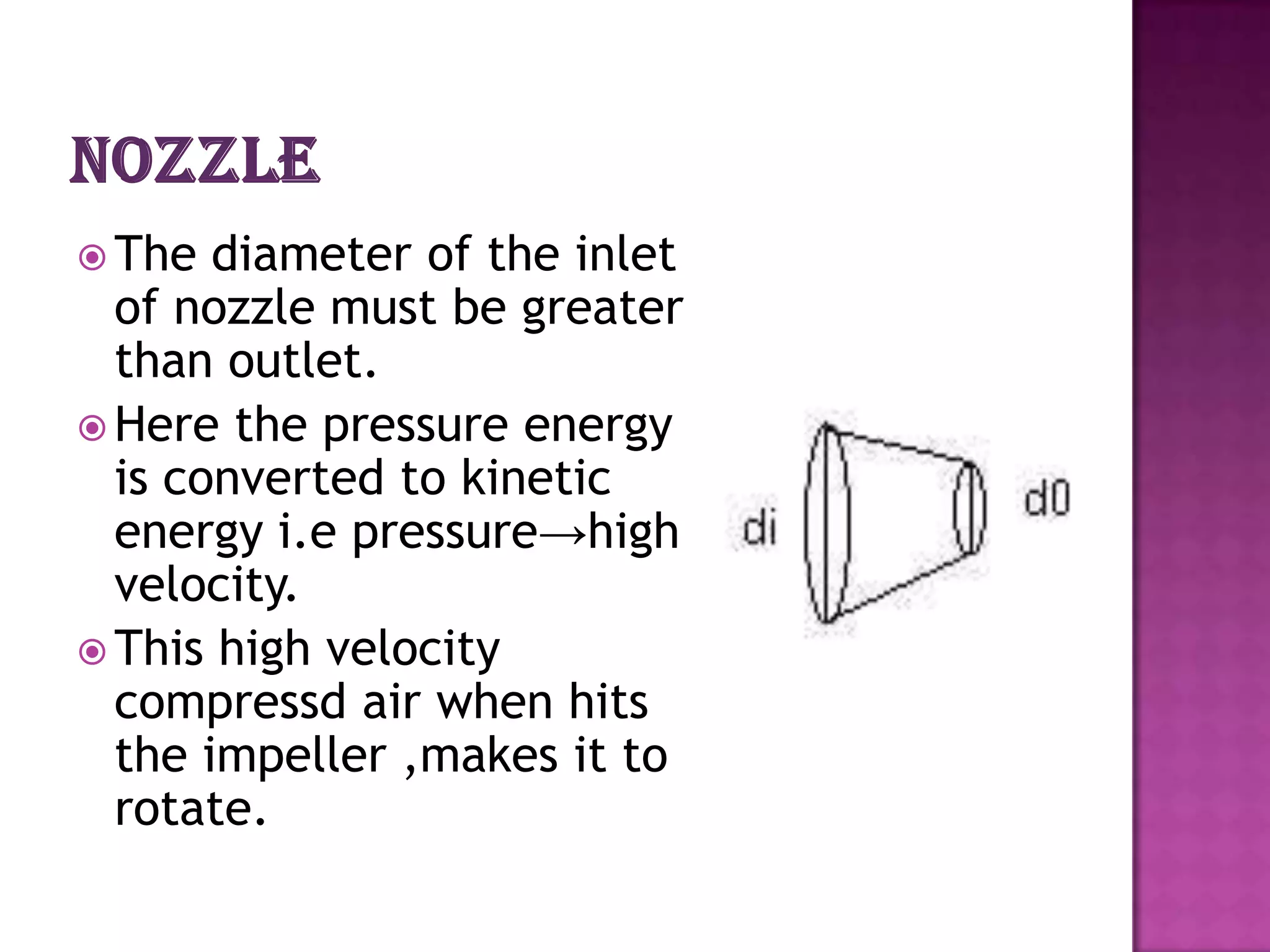
Explanation of vehicle load effects on speed breakers, air compression, and conversion of pressure energy to kinetic energy.
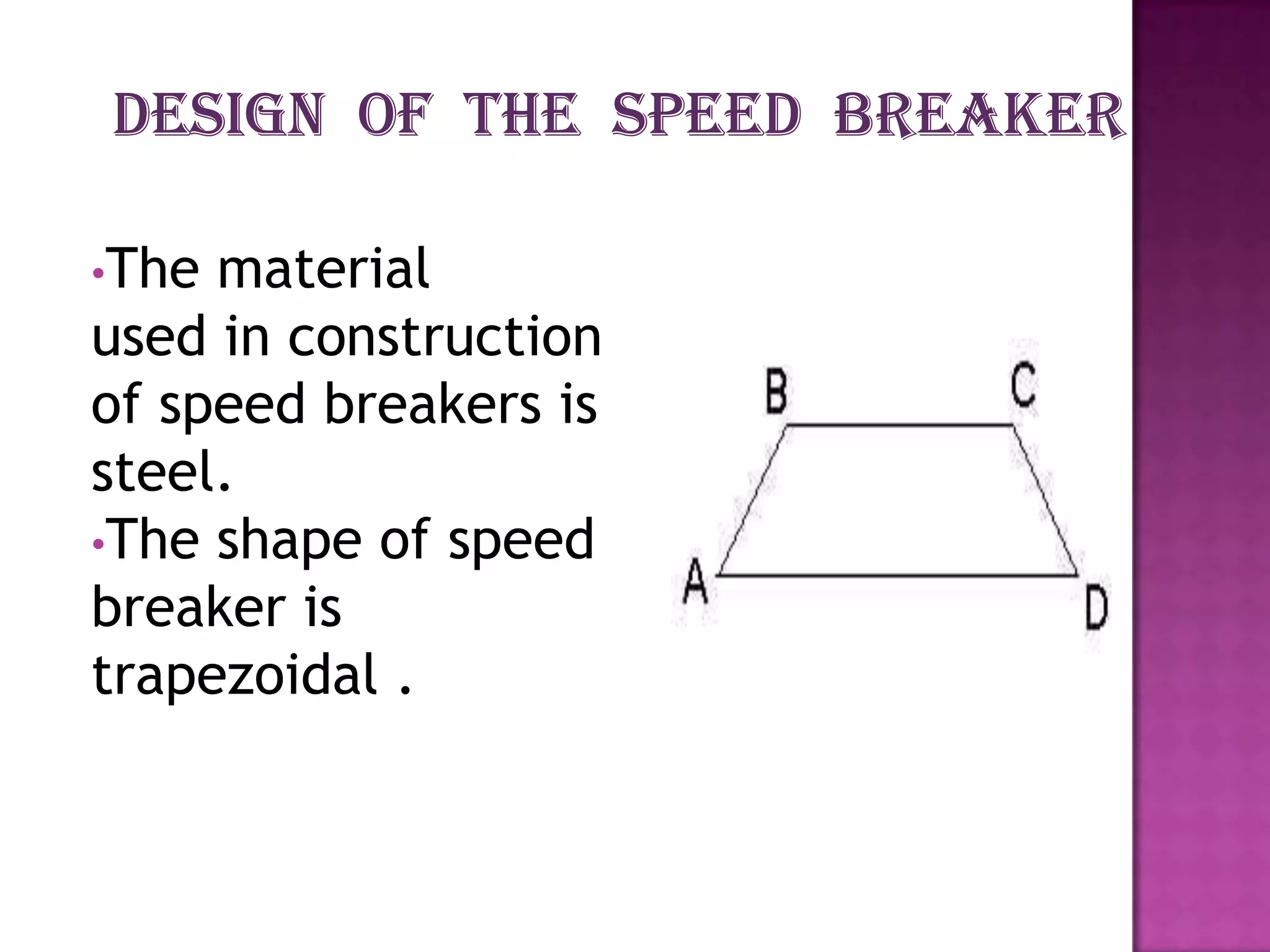
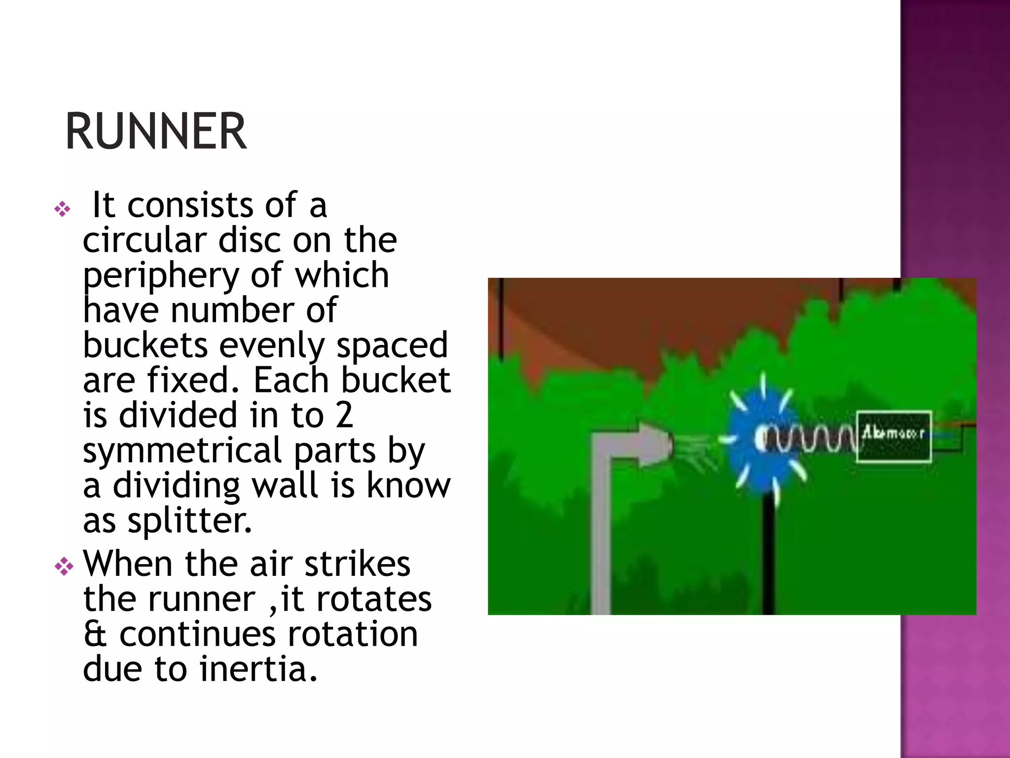
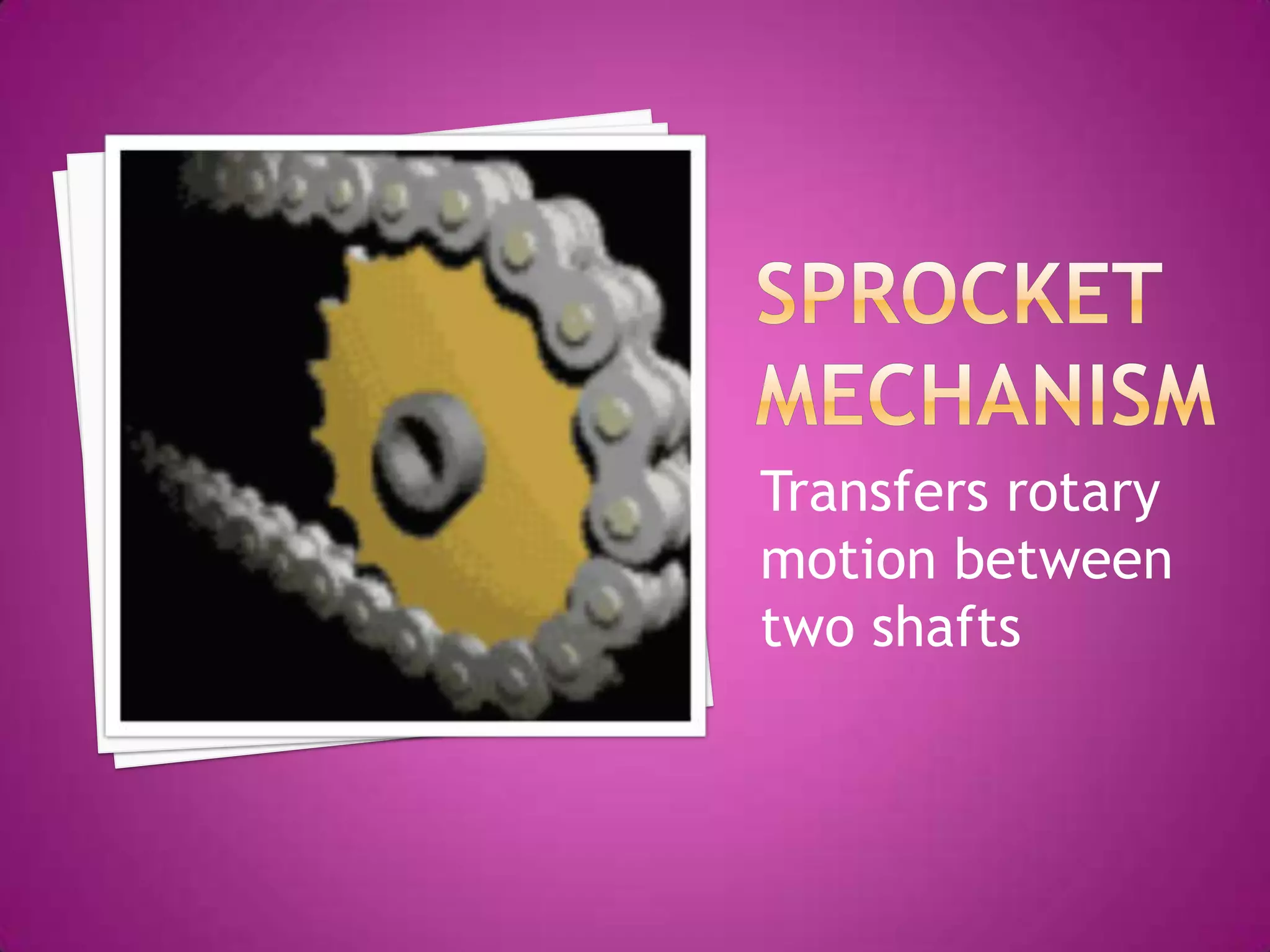
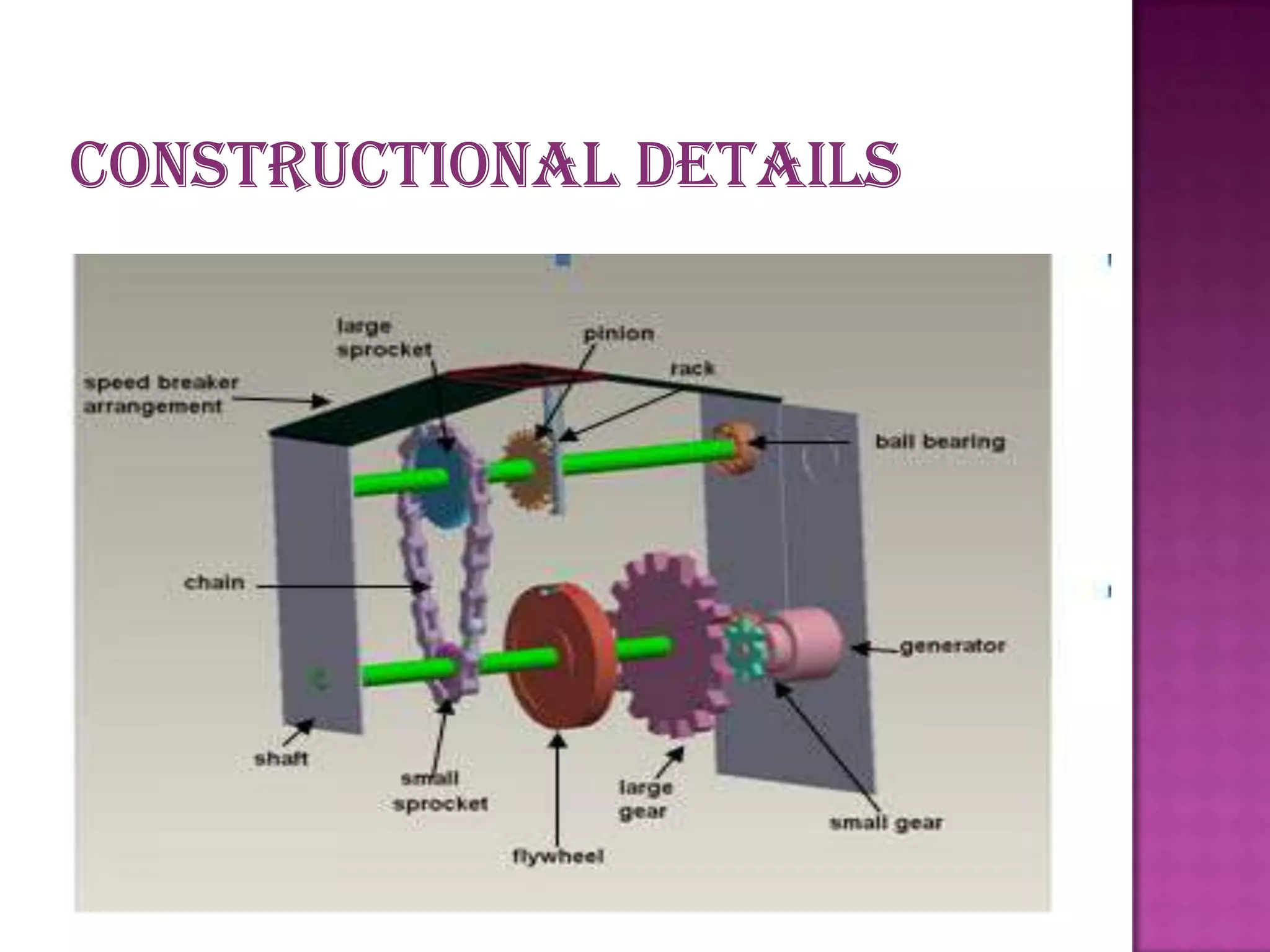
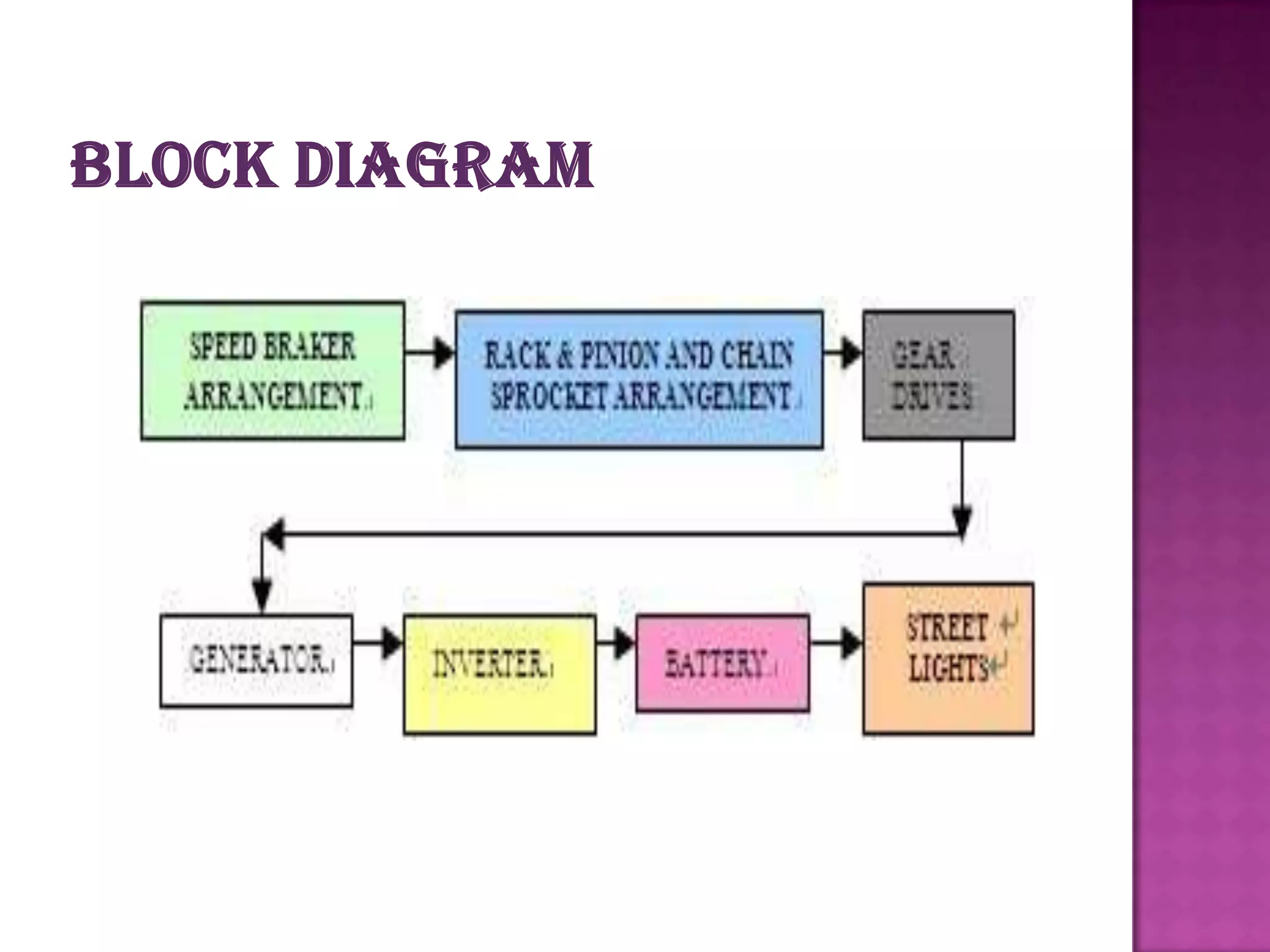
Describes major components like casings, runners, and generators used in the mechanical energy to electricity conversion process.
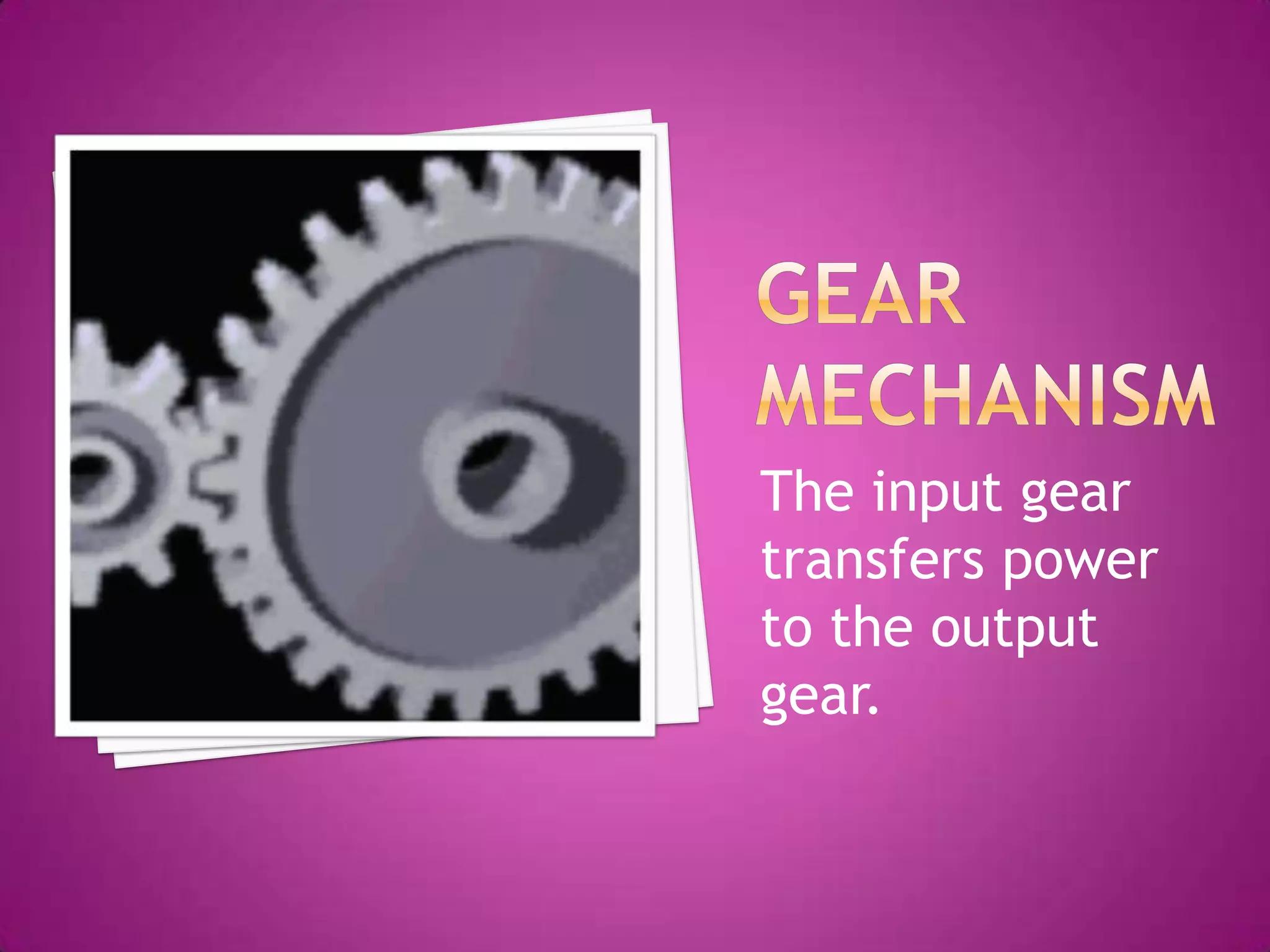
Focuses on the gear arrangements and methods to maintain uniform rotational speeds in the generator system.
Explains how reciprocating motion from speed breakers is converted into rotary motion using rack and pinion mechanisms.
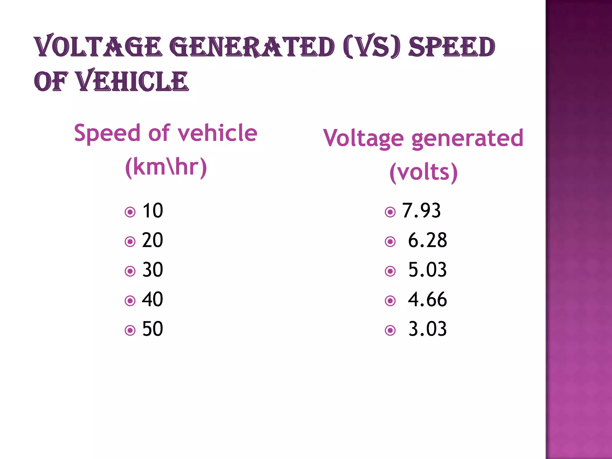
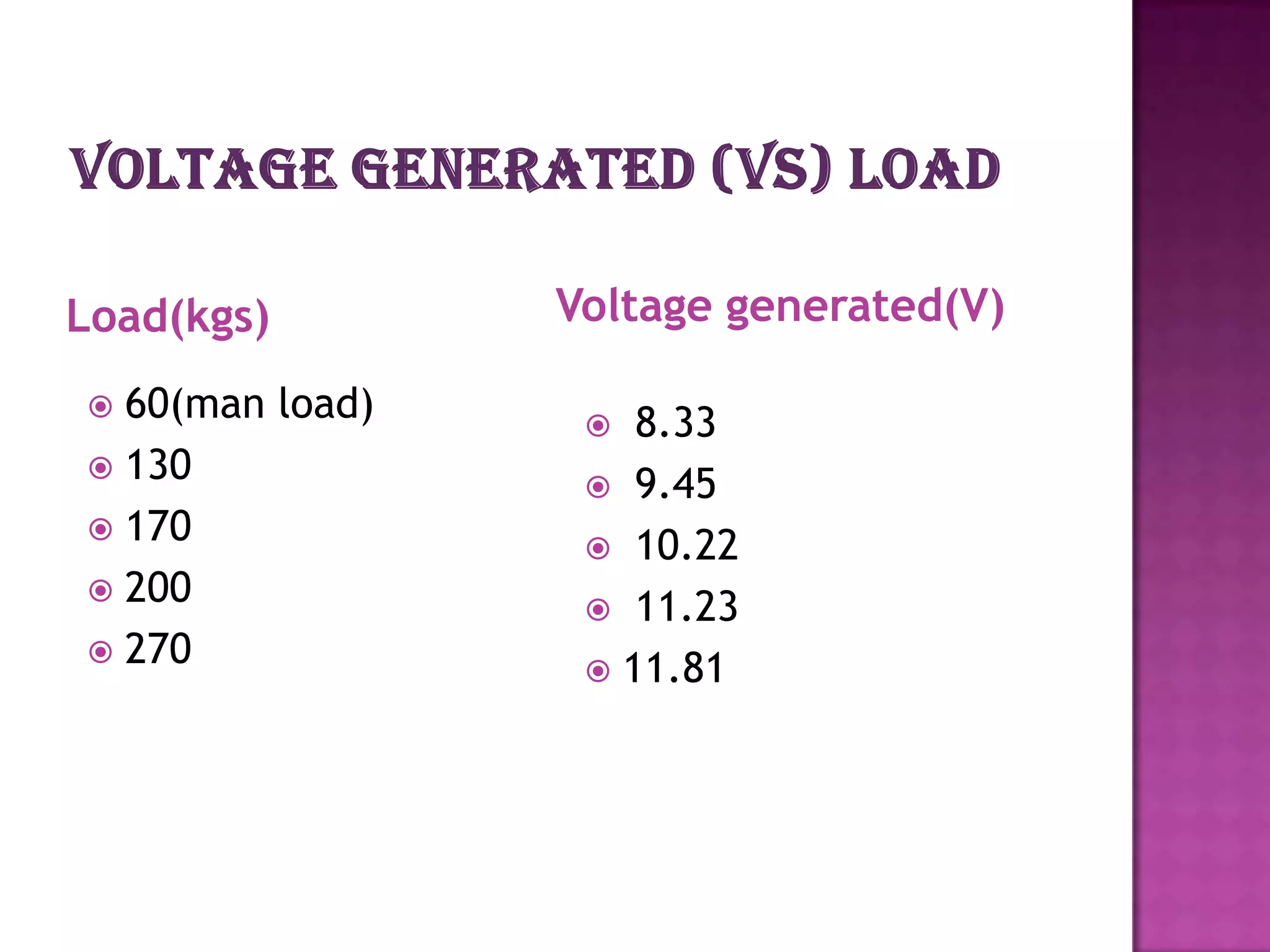
Presents data on voltage generation based on vehicle speed and load in kilograms.
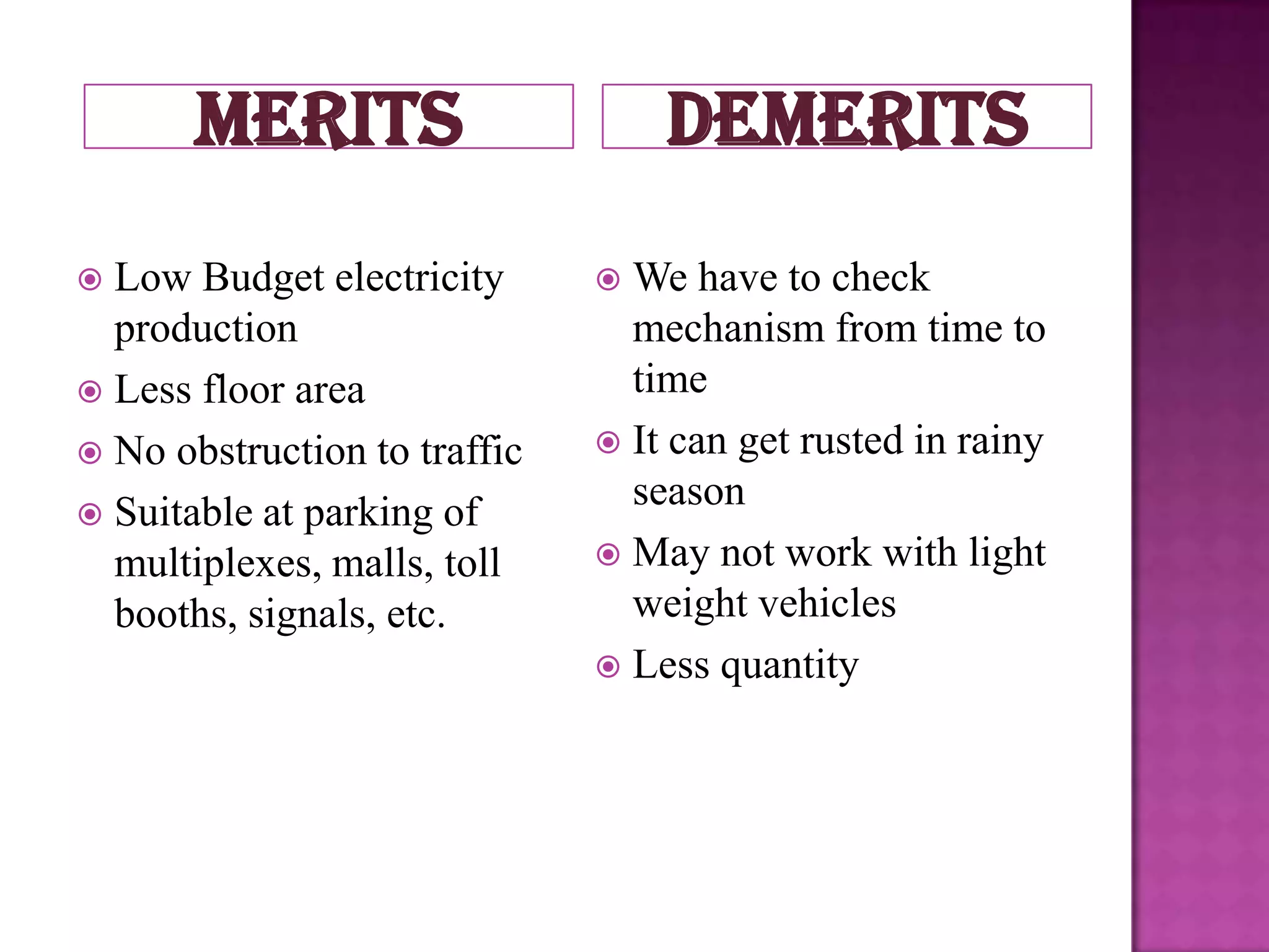
Summarizes advantages like low budget electricity and drawbacks such as maintenance and weather impacts on the mechanism.
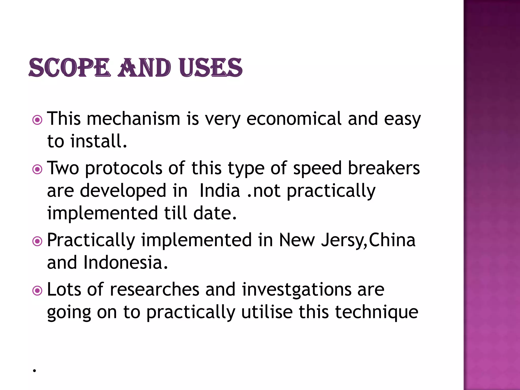
Discusses the urgency for alternative energy sources and highlights ongoing research on non-conventional energy methods.
PREPARED BY-
JASHOBANTI BISWAL
REGDN. NO-0901106119
ELECTRICAL ENGINEEERING DEPARTMENT
2.
Introduction
Differentmechanisms
Spring coil mechanism
Rack pinion mechanism
MERITS and demerit
scope and uses
CONCLUSION
3.
A large amount of energy is wasted
at the speed breakers through
friction , every time a vehicle passes
over it.
So electricity can be generated using
the vehicle weight (potential energy)
as input.
So, this is a small step to try to
improve this situation.
OUTOF THEABOVE METHODS
CRANK-SHAFT MECHANISM & ROLLER
MECHANISM ARE NOT USED BECAUSE OF
THE DEMERITS RELATED TO THESE METHODS.
SOONLY SPRING COIL MECHANISM &
RACK- PINION MECHANISM ARE
DISCUSSED.
Here we are making the speed breaker of
vibrating type, when a vehicle crosses the
speed breaker, it gets pressed and then it
gets back to its original position.
Dimensions of speed breaker:-
Height : 0.2m
Width : 0.4m
Length : 4m
8.
•The material
used inconstruction
of speed breakers is
steel.
•The shape of speed
breaker is
trapezoidal .
9.
• Height: 0.35m
•Length : 4m
• Width :0.45m
• The bottom layer of
the trench is filled
with concrete or with
wooden plates of
0.5m.
•This is for cushion
effect.
10.
The actual height of spring is 0.3m before loading.
The deflection of the spring is given by
δ = 64 w *n*N*R^3 /(Gd^4)
where
δ-deflection (in our case maximum δ =0.1m)
w=designed load
R= mean diameter of coil
d =diameter of wire
n=no of spring turns
G= Modulus of rigidity = 8*10^4 N/mm2
N= No. of springs
The no of turns in the spring to get the deflection of
0.1m is given by
n= δGd^4/(64 w*N*R^3)
Maximum load on the speed
breaker is when the
vehicle is on the middle
of the speed breaker.
When the load is on the
speed breaker, the
volume of air compressed
by it is found by,
Volume of compressed air
= Volume of air in base –
Volume of spring
= (x m^3)/s
13.
When the pressure
in the FRL unit
exceeds the
defined level the
valve opens and
the pressurized air
is given to the
nozzle.
14.
The diameter of the inlet
of nozzle must be greater
than outlet.
Here the pressure energy
is converted to kinetic
energy i.e pressure→high
velocity.
This high velocity
compressd air when hits
the impeller ,makes it to
rotate.
15.
CONSISTS -
Casing
Runner and buckets
CASING-
This is provided to safeguard device against
accidents.
16.
Itconsists of a
circular disc on the
periphery of which
have number of
buckets evenly spaced
are fixed. Each bucket
is divided in to 2
symmetrical parts by
a dividing wall is know
as splitter.
When the air strikes
the runner ,it rotates
& continues rotation
due to inertia.
17.
An electricalgenerator is a machine which
converts mechanical energy in to electrical
energy.
The output of the alternator is used to light
the street lights & is rectified & stored in
batteries.
This is usedto regulate the energy and
maintain the energy at an uniform
level so that the shaft rotate at an
uniform r.p.m
24.
Herethe reciprocatingmotion of the speed-
breaker is converted into rotary motion using
the rack and pinion arrangement.
Rackand pinion gears normally change rotary
motion into linear motion, but sometimes we
use them to change linear motion into rotary
motion.
25.
The axisof the pinion is coupled with the sprocket
arrangement.
The axis of the smaller sprocket is coupled to a
gear arrangement.
Finally the gear arrangement is coupled with the
generator
merits demerits
Low Budget electricity We have to check
production mechanism from time to
Less floor area time
No obstruction to traffic It can get rusted in rainy
season
Suitable at parking of
multiplexes, malls, toll May not work with light
booths, signals, etc. weight vehicles
Less quantity
30.
This mechanismis very economical and easy
to install.
Two protocols of this type of speed breakers
are developed in India .not practically
implemented till date.
Practically implemented in New Jersy,China
and Indonesia.
Lots of researches and investgations are
going on to practically utilise this technique
.
31.
The existing source of energy such as coal, oil etc
may not be adequate to meet the ever increasing
energy demands. These conventional sources of
energy are also depleting and may be exhausted.
These are some non-conventional methods of
producing energy. This project is a one step to path
of exploring the possibilities of energy from
several non-conventional energy sources.