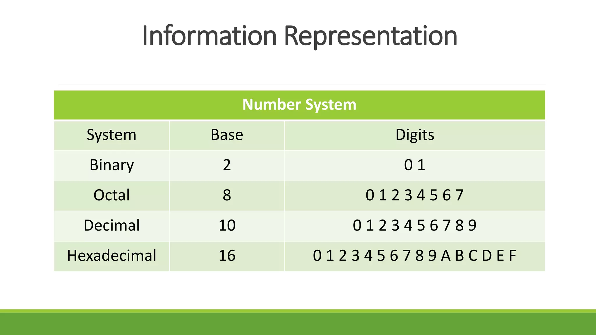
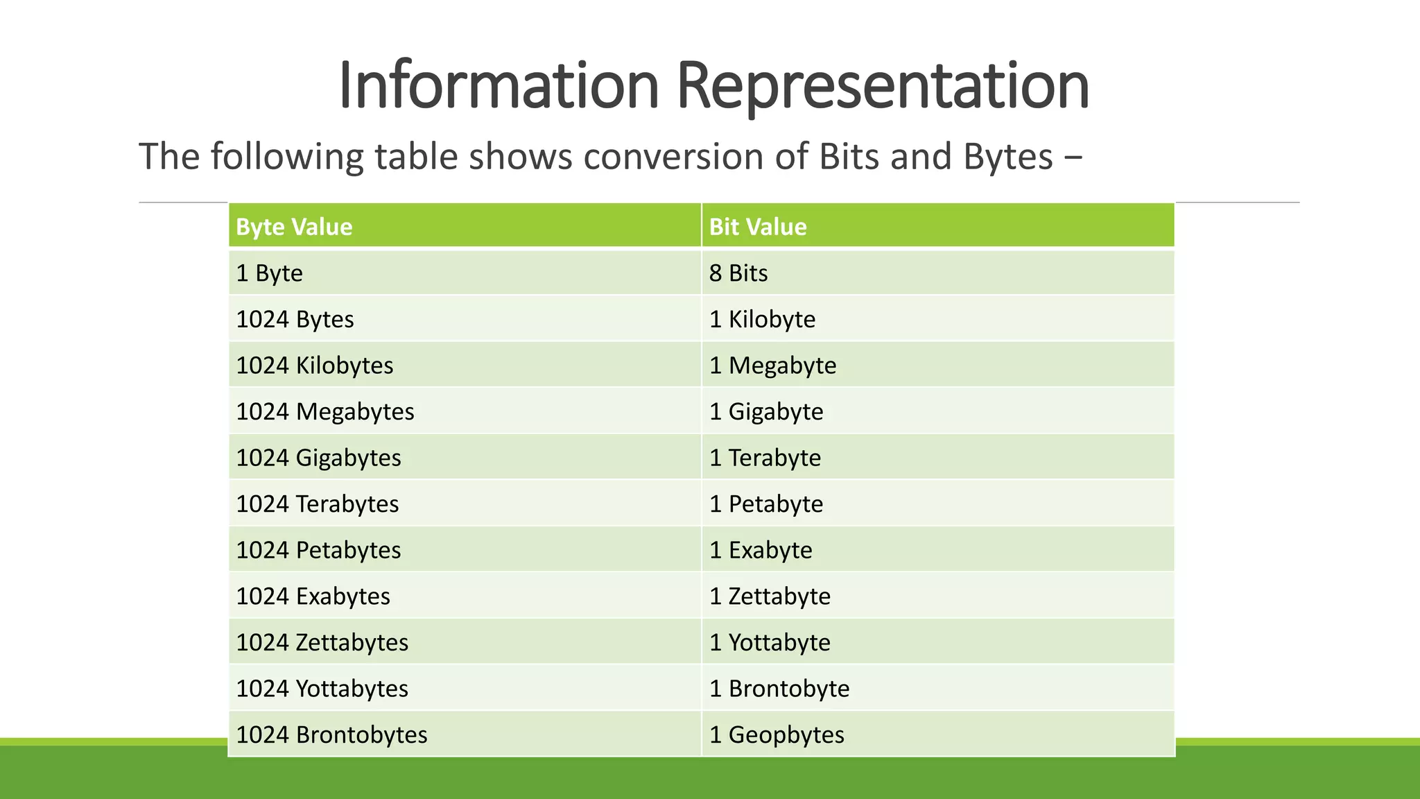
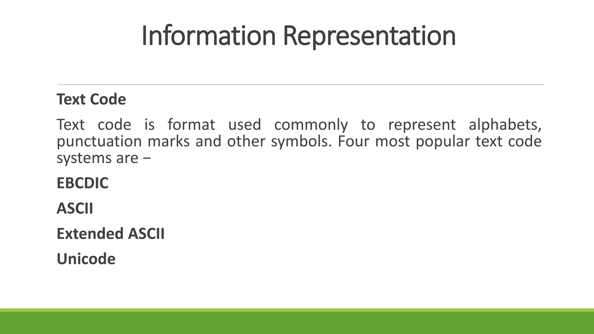
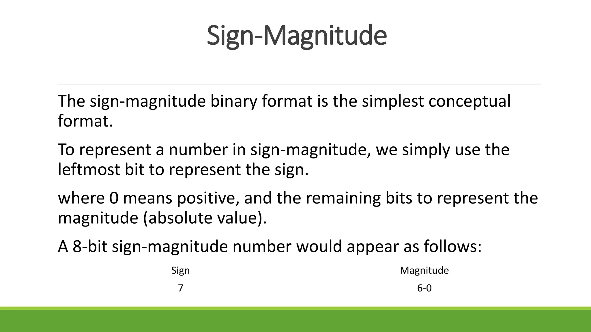
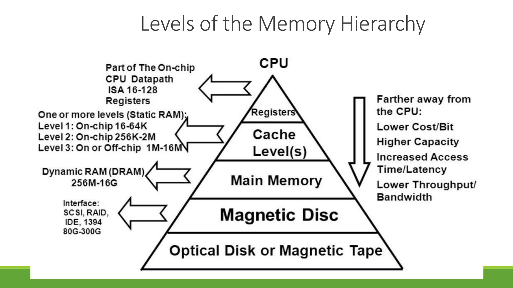
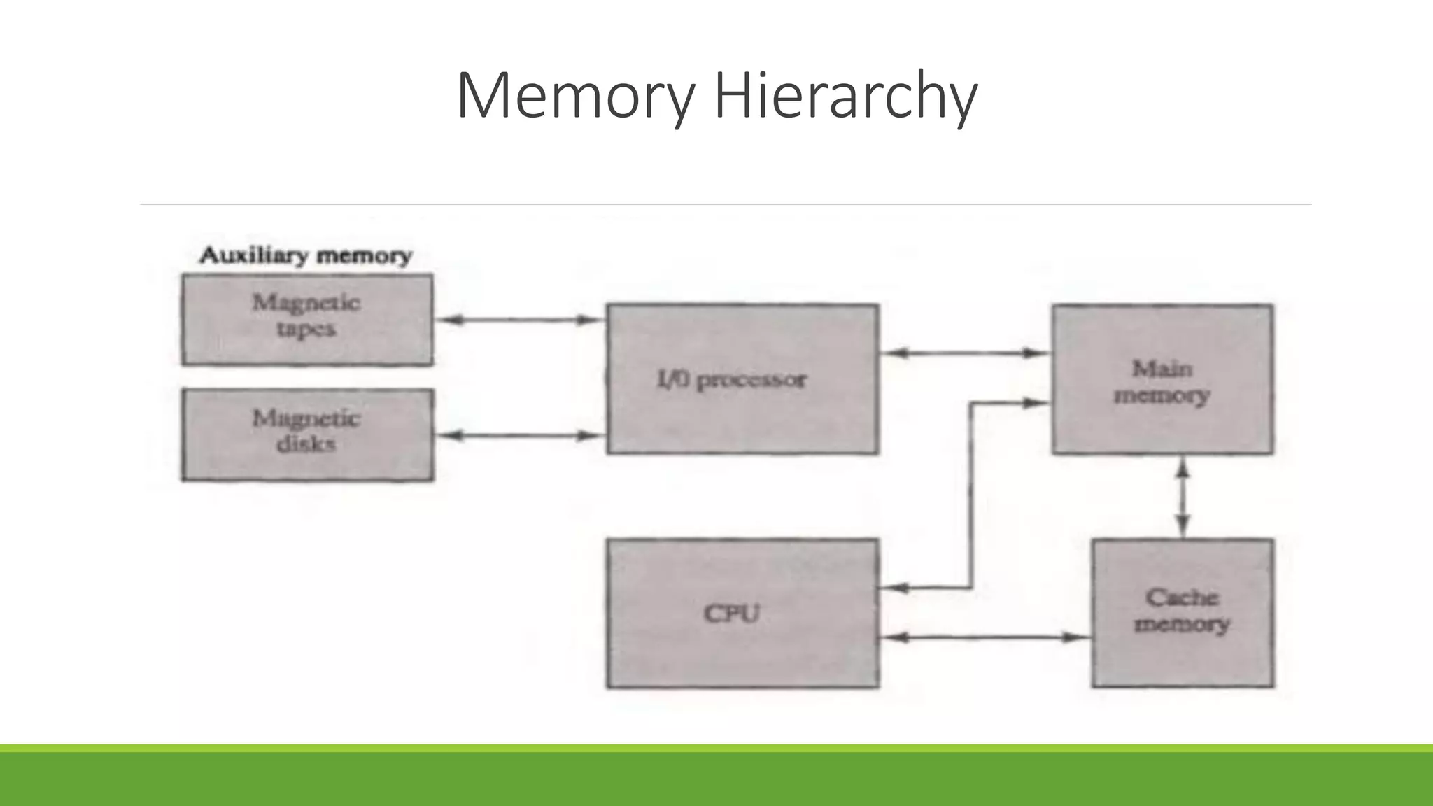
The document outlines the syllabus for a computer system architecture course at Medicaps University, covering key concepts such as information representation, memory types, arithmetic operations, algorithms for multiplication and division, and the significance of memory hierarchy. It details various number systems (binary, octal, decimal, hexadecimal), data representation, and methods for performing arithmetic operations using fixed-point representation along with Booth's multiplication algorithm. Additionally, it explains memory components, including main memory and auxiliary memory, and discusses the bootstrap loader's role in starting up the computer's software.

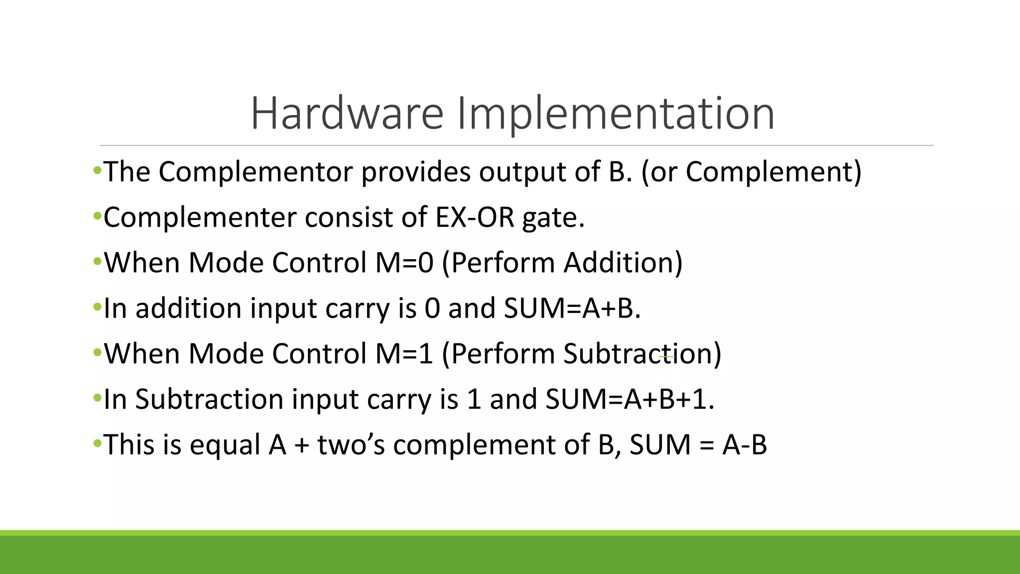
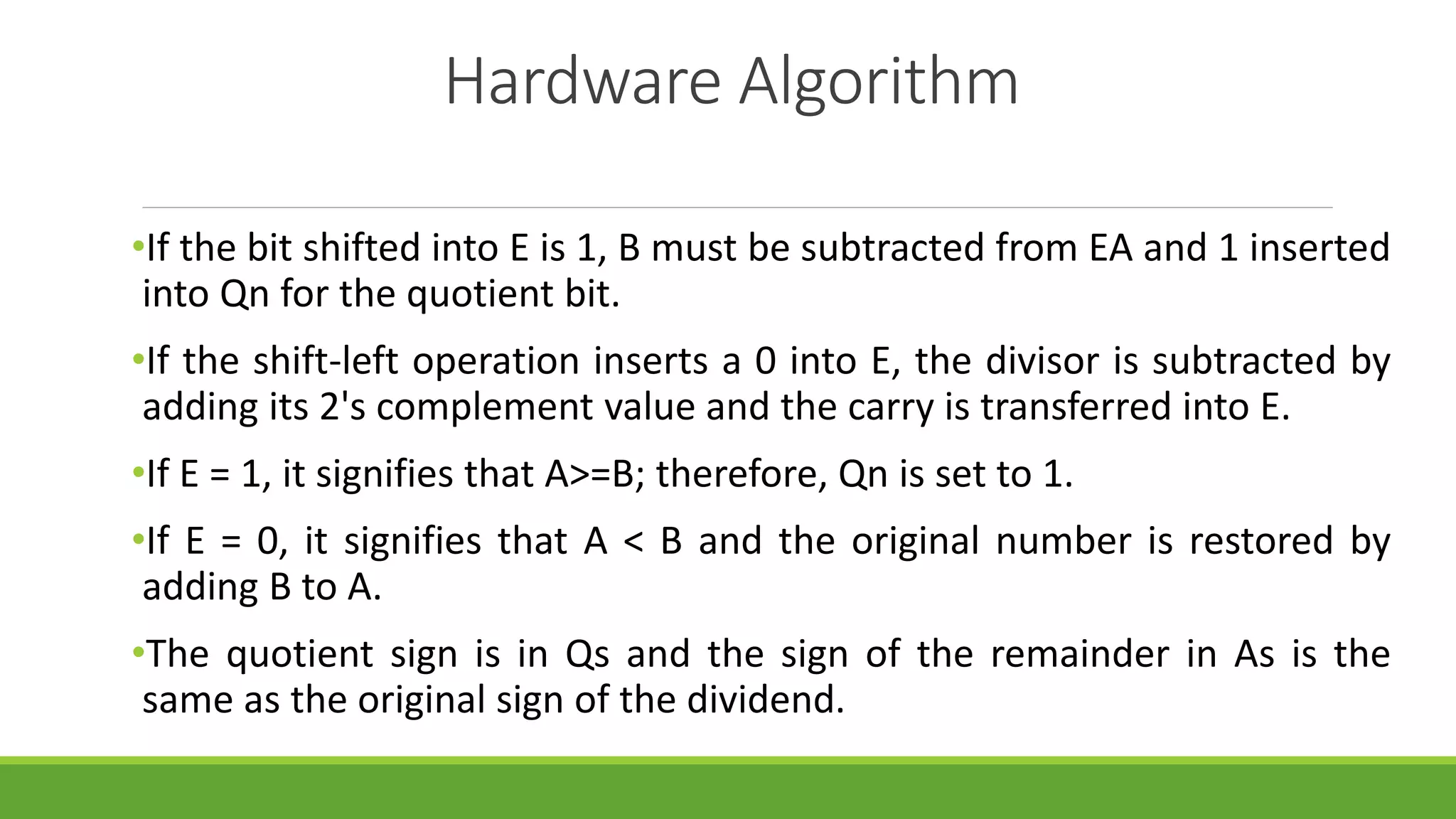

![Assignment for 1st Week [Unit-3 (I)]
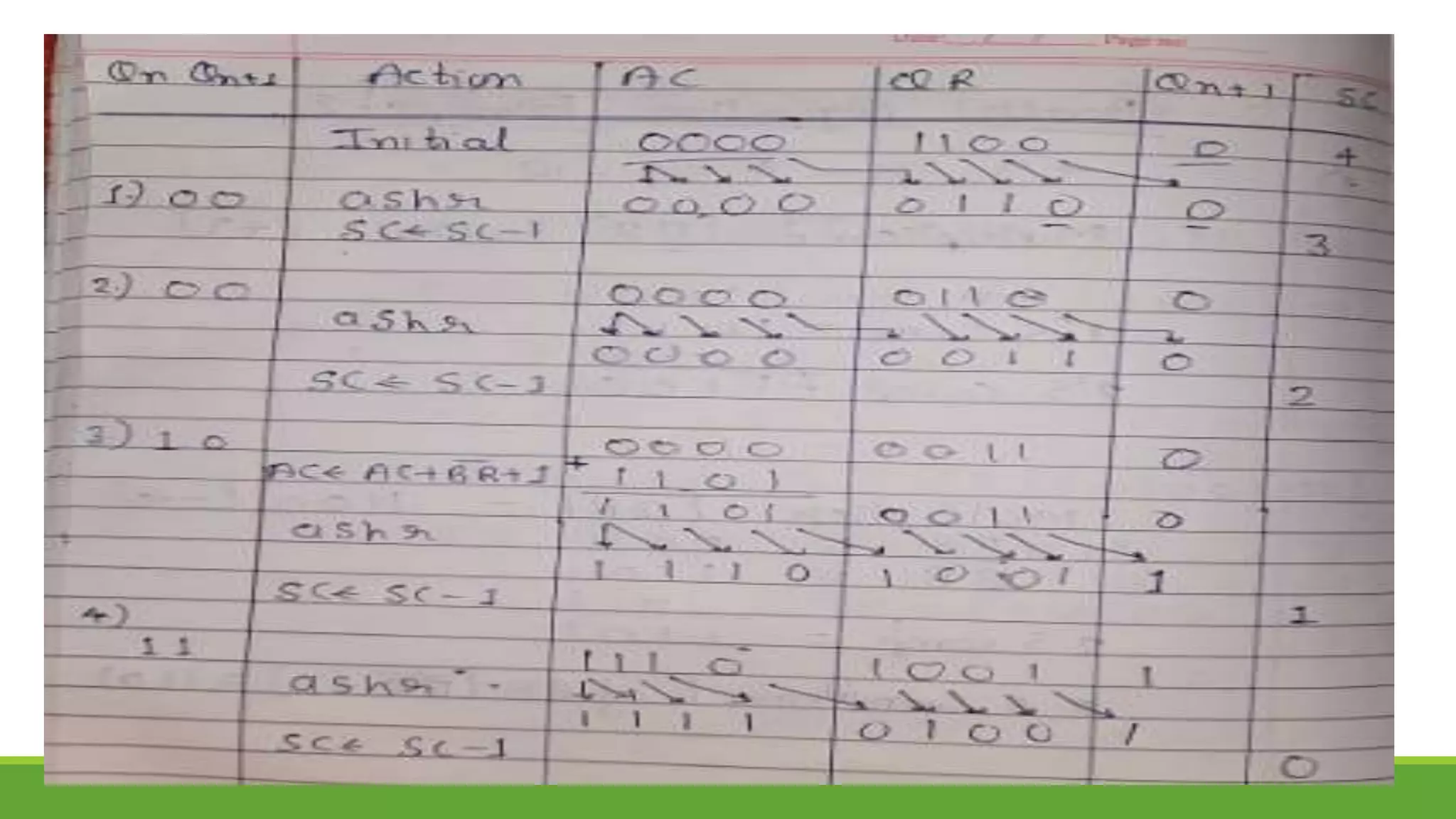
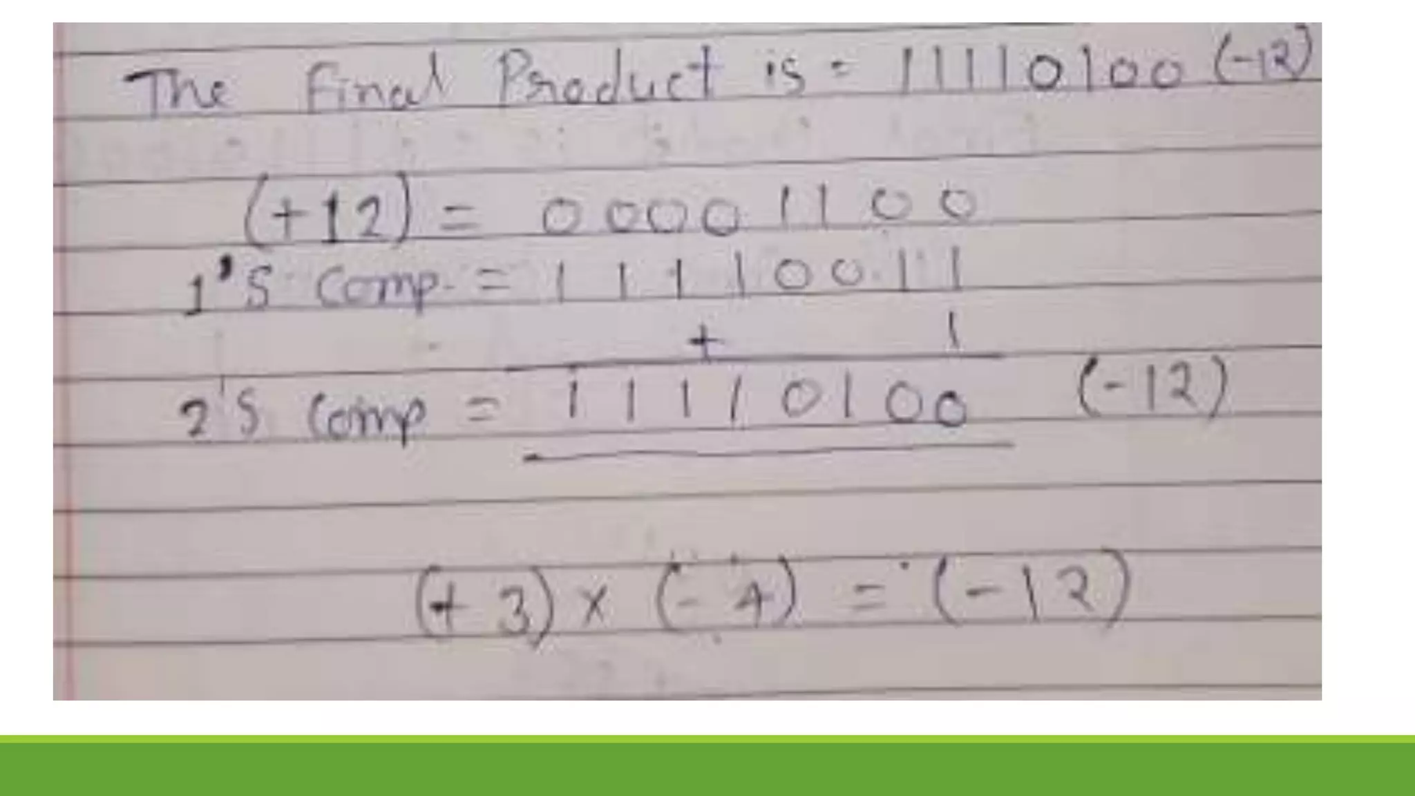
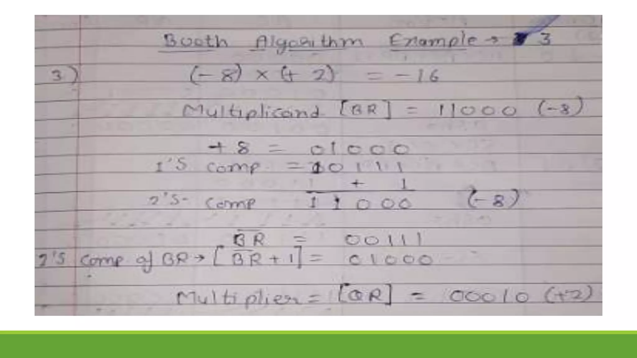
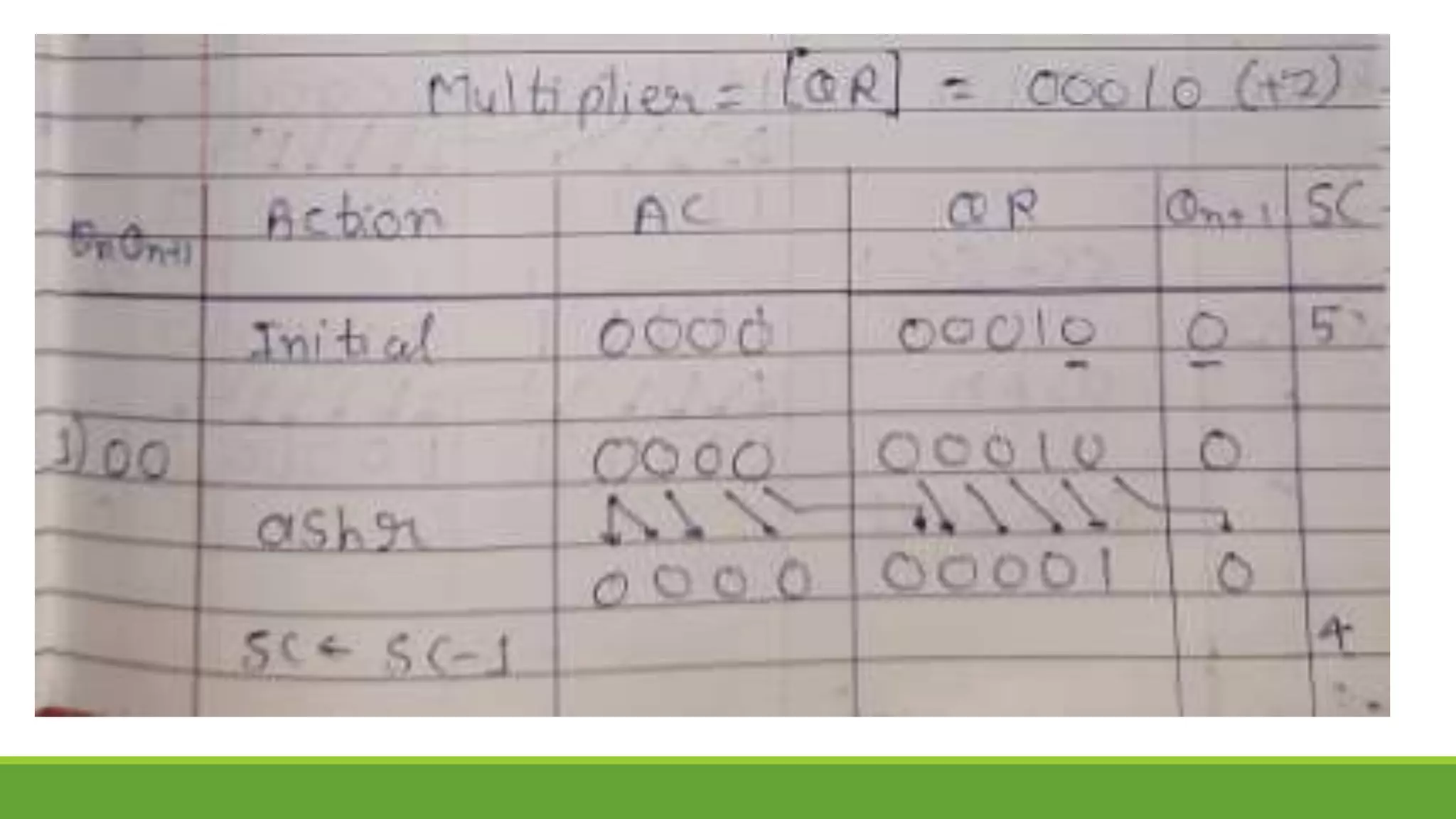
Q.1 Show the step-by-step multiplication process using Booth algorithm when the following
binary numbers are multiplied. Assume 5-bit registers that hold signed numbers. The
multiplicand in both cases is + 15.
a. (+15) x (+13) b. (+15) X (-13)
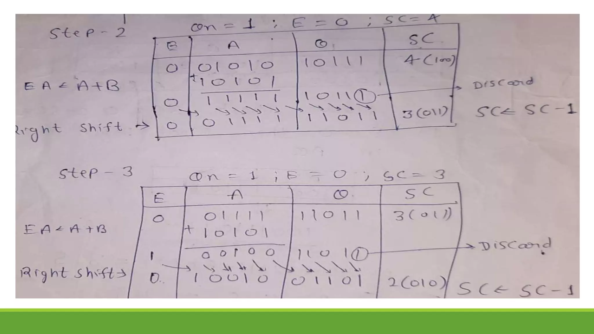
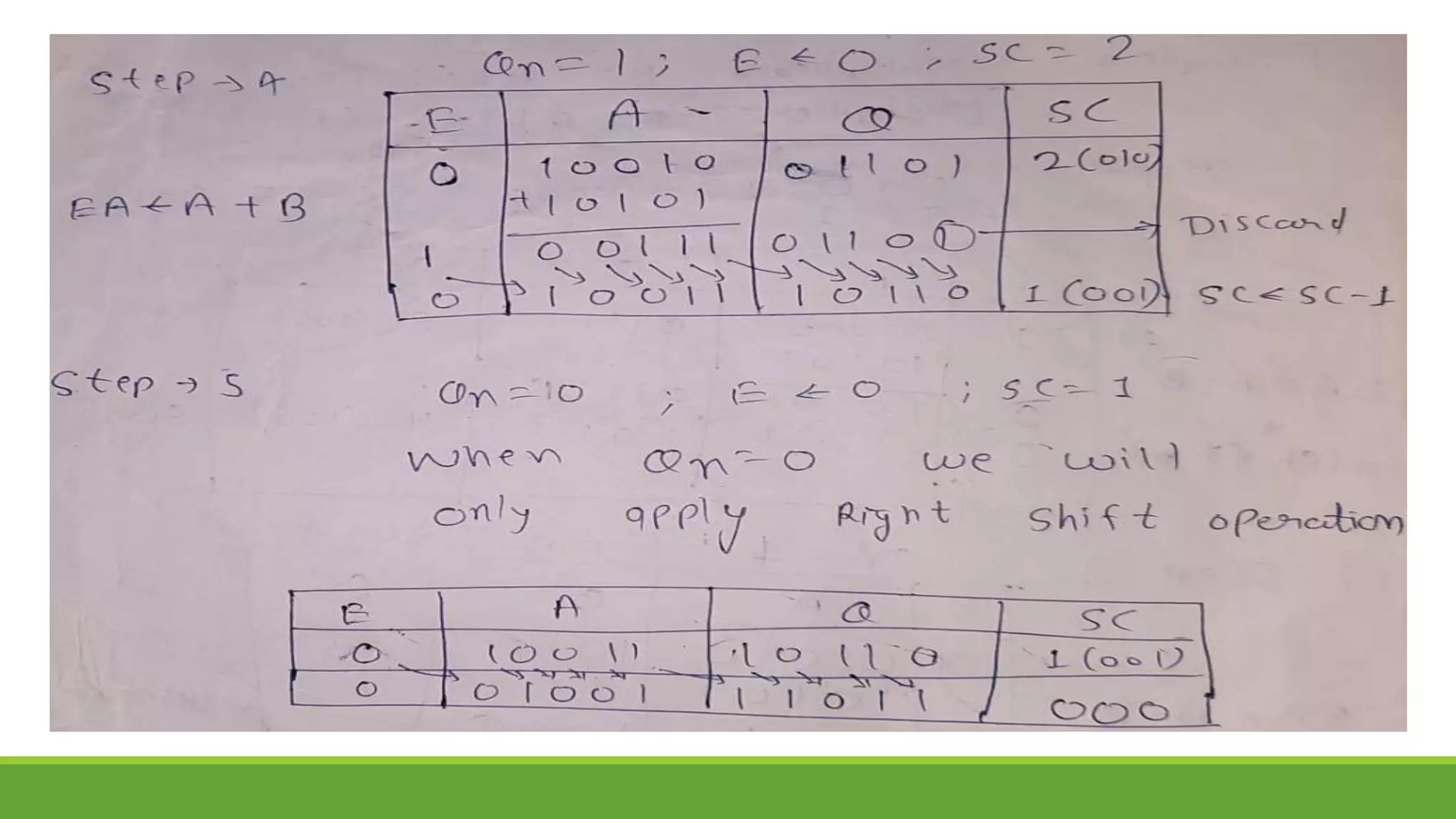
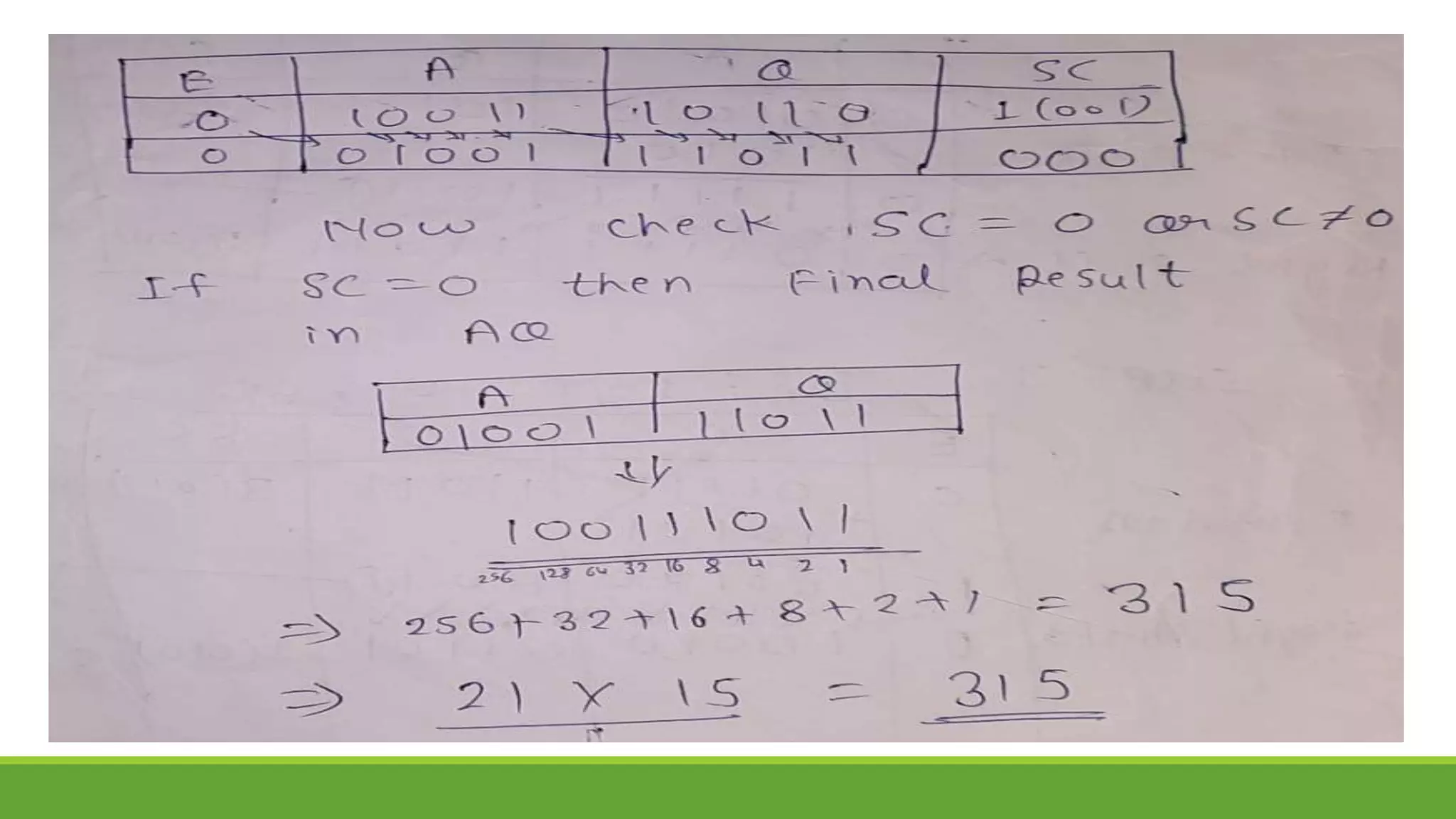
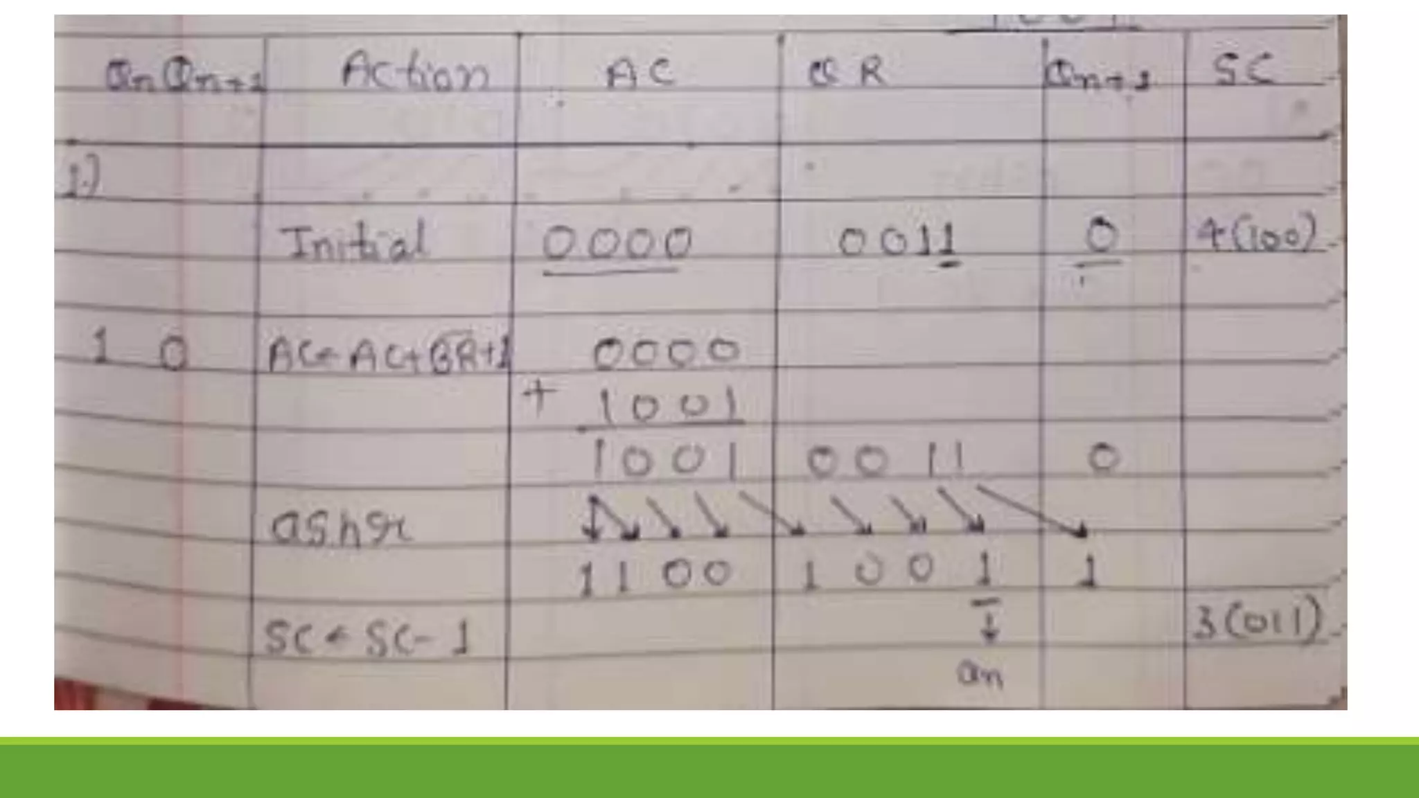
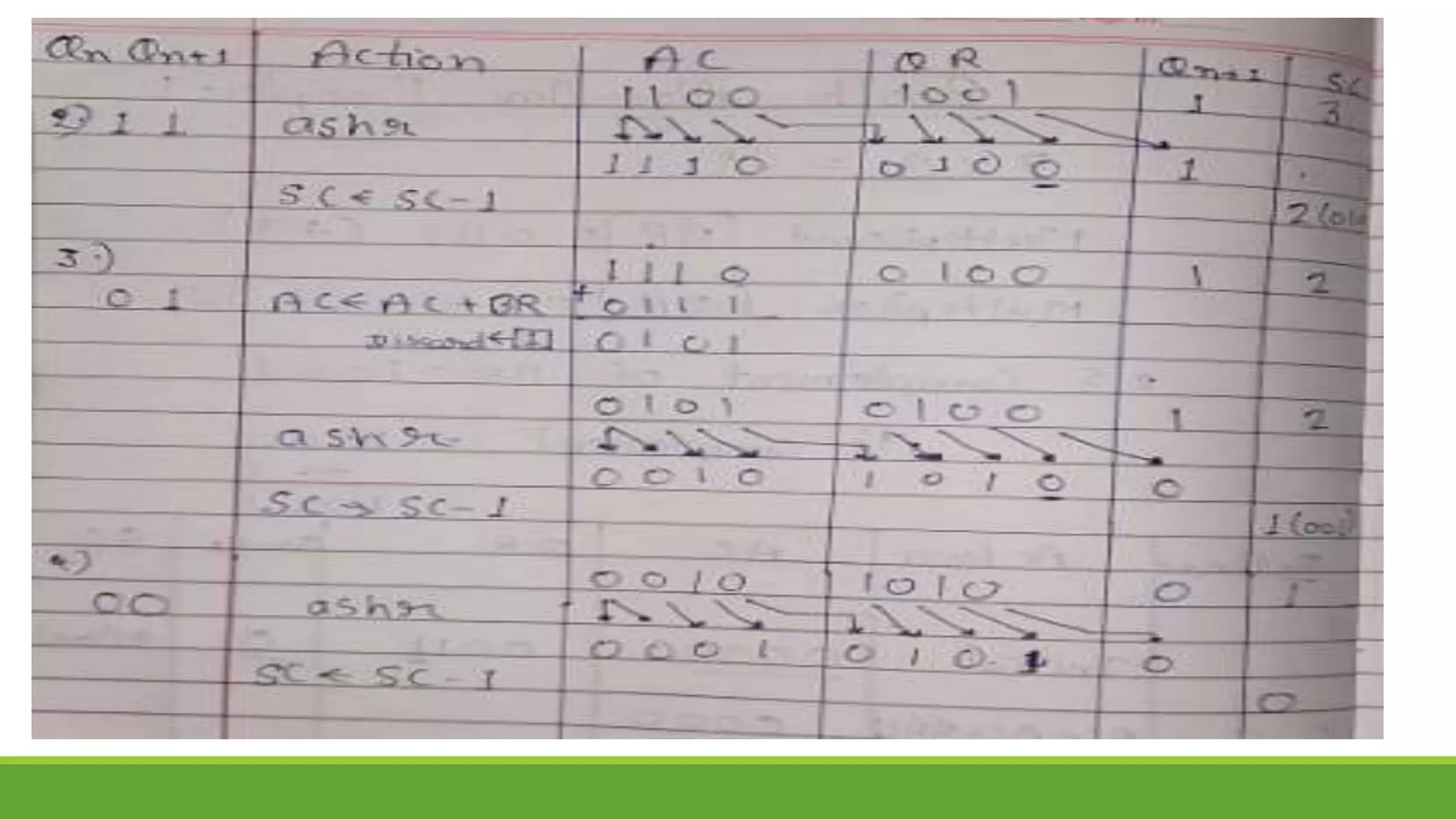
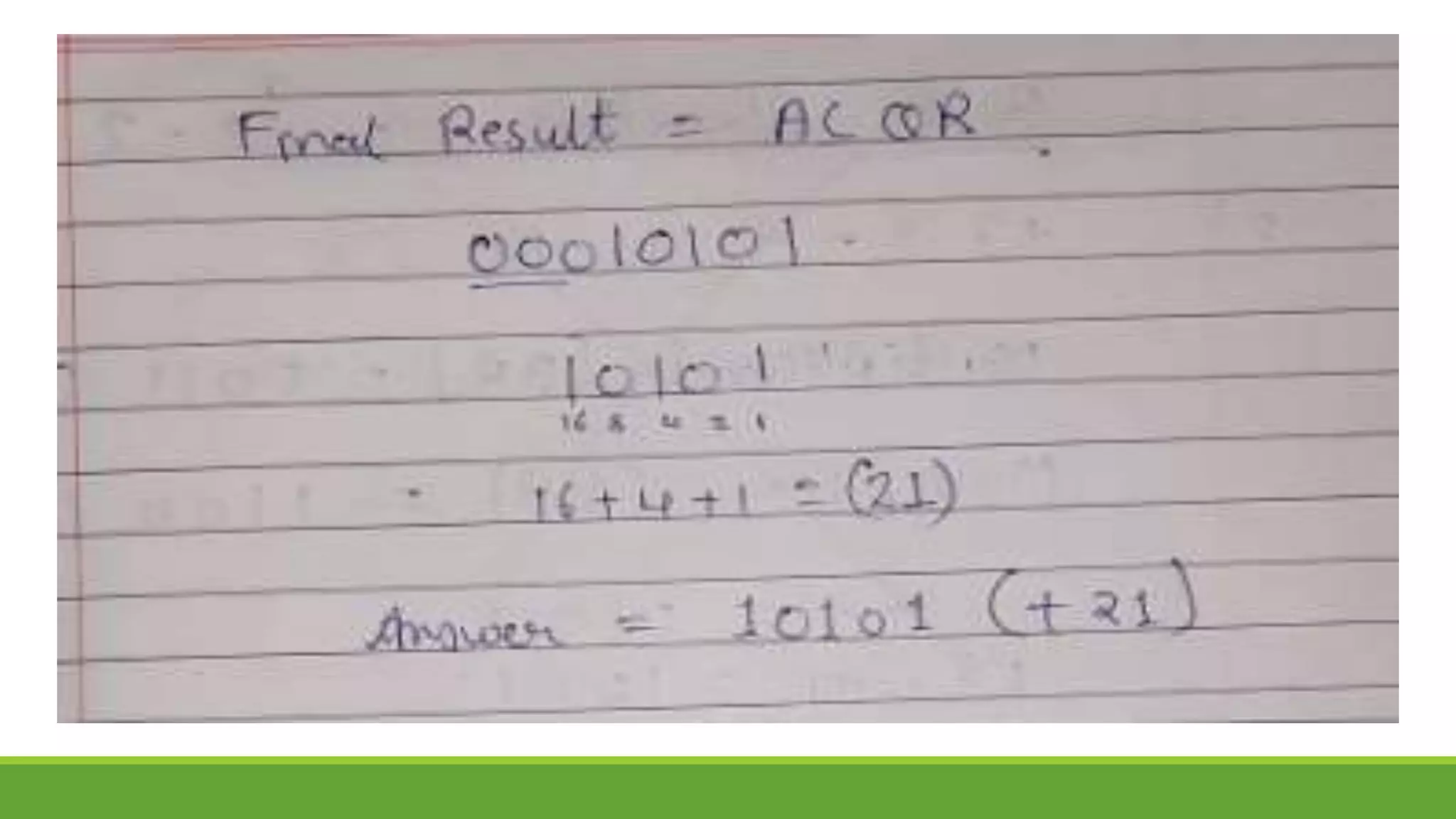
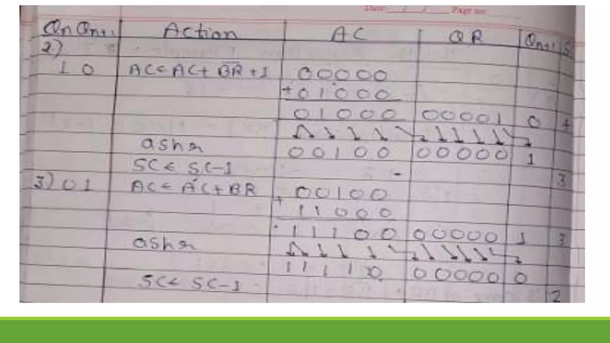
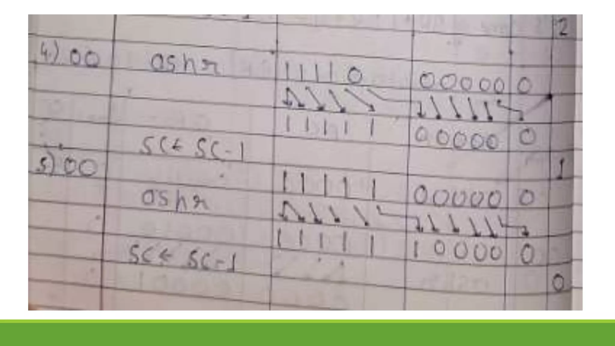
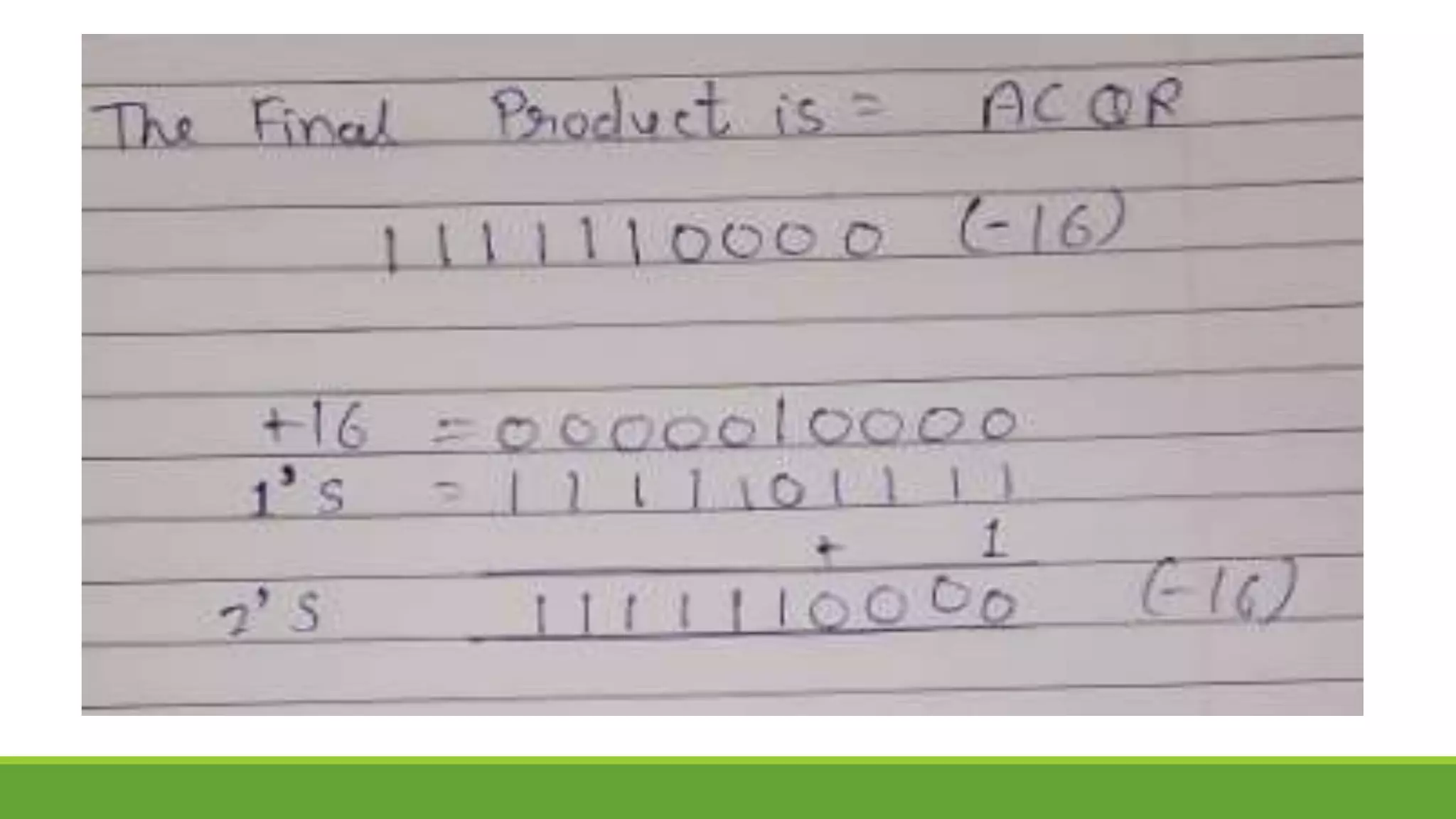
Q.2 Show the contents of registers E, A, Q, and SC during the process of multiplication of
two binary numbers, 11111 (multiplicand) and 10101 (multiplier). The signs are not
included.
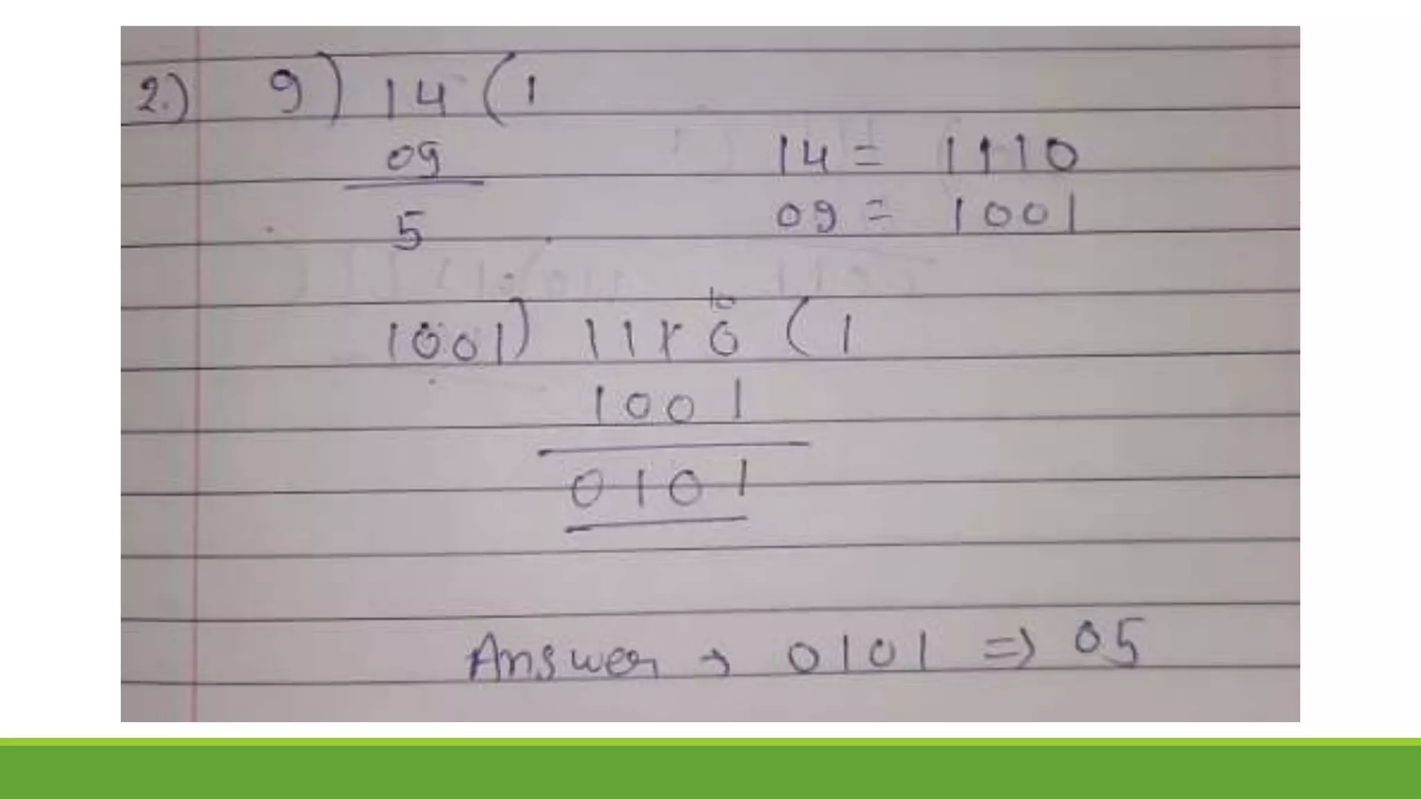
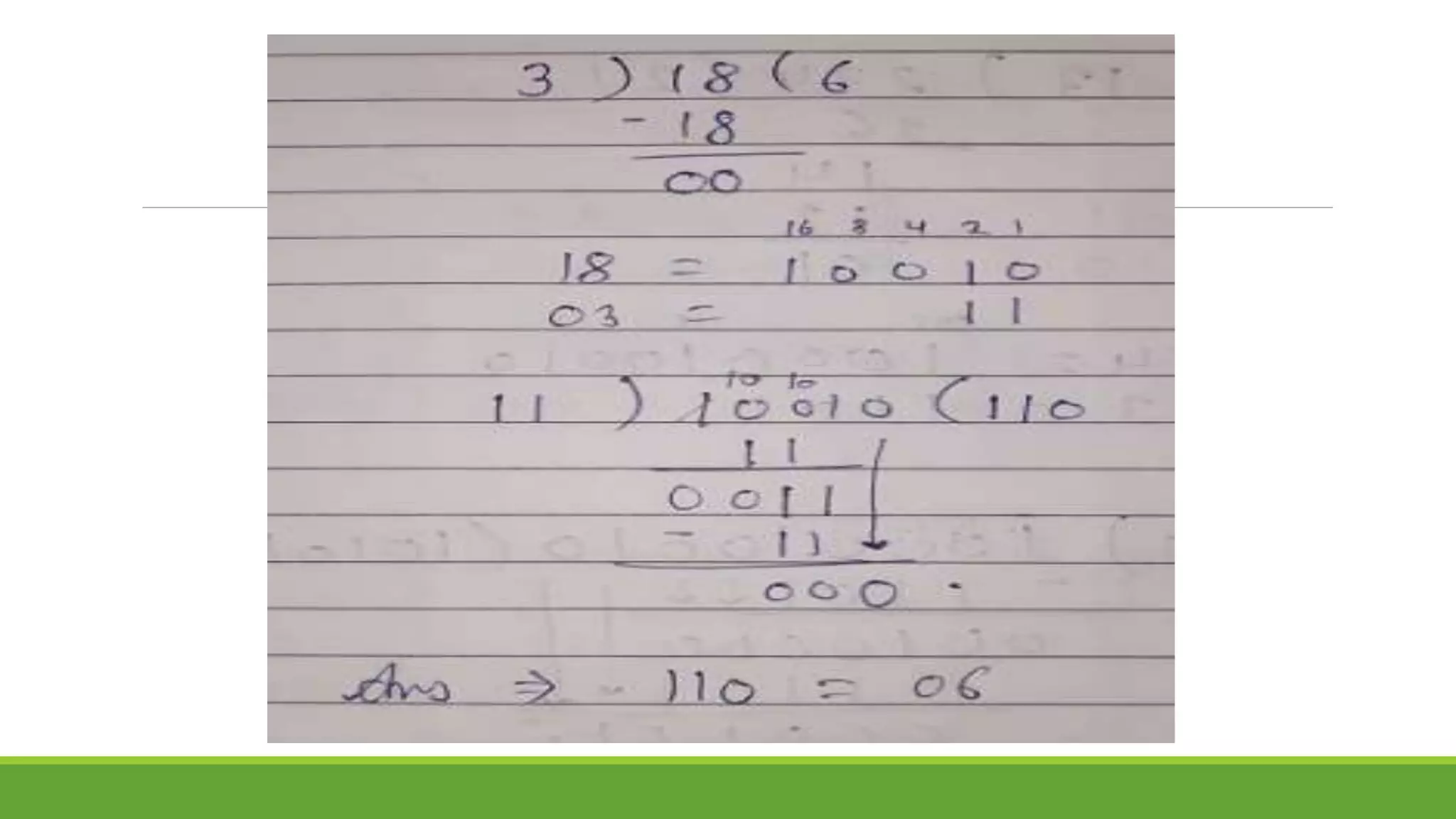
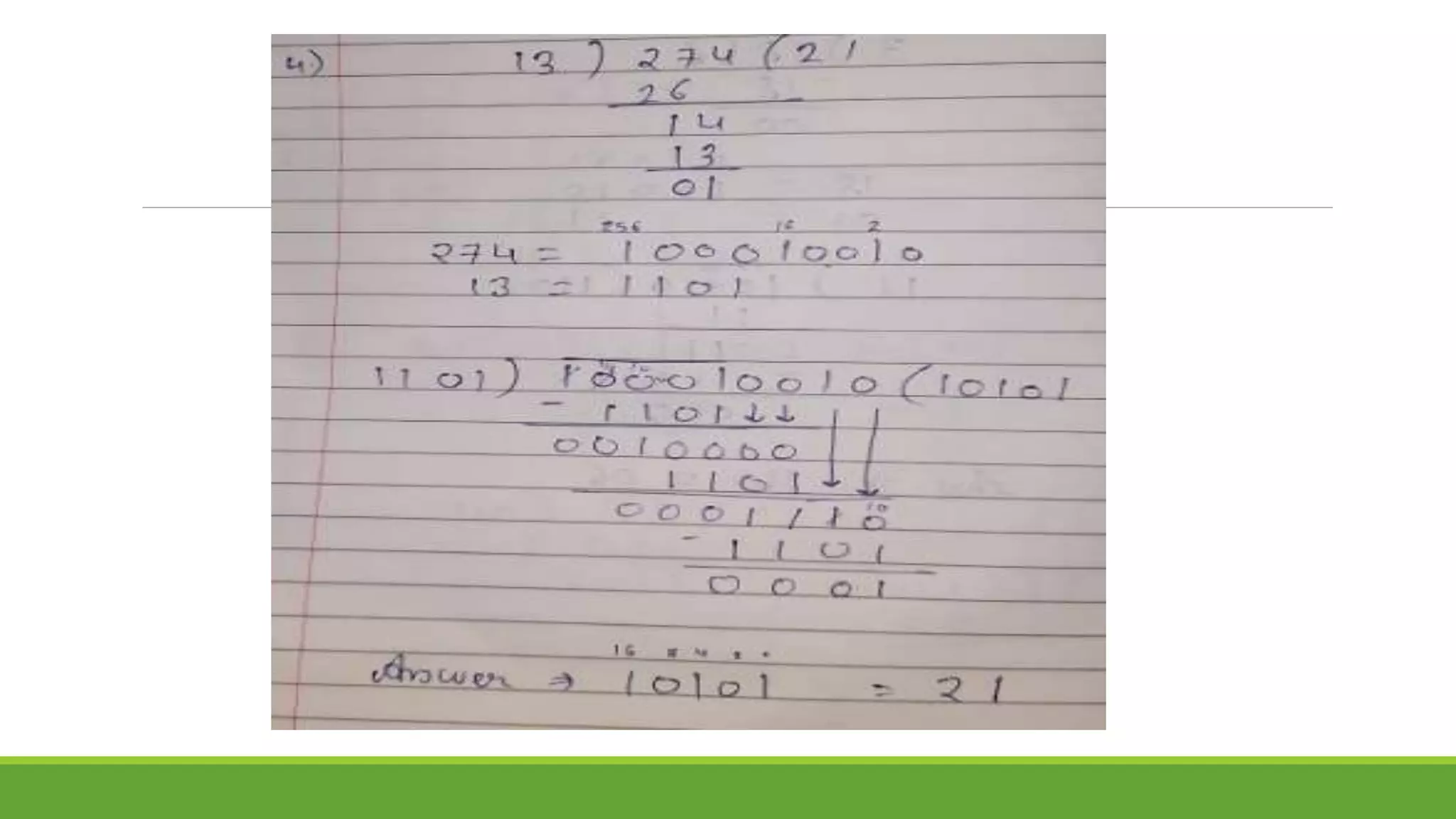
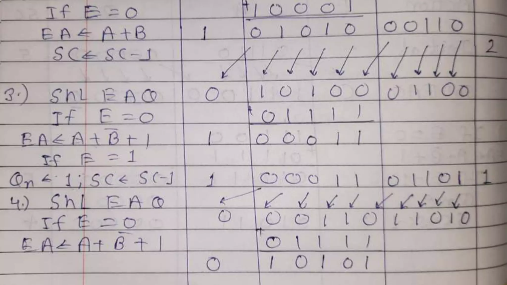
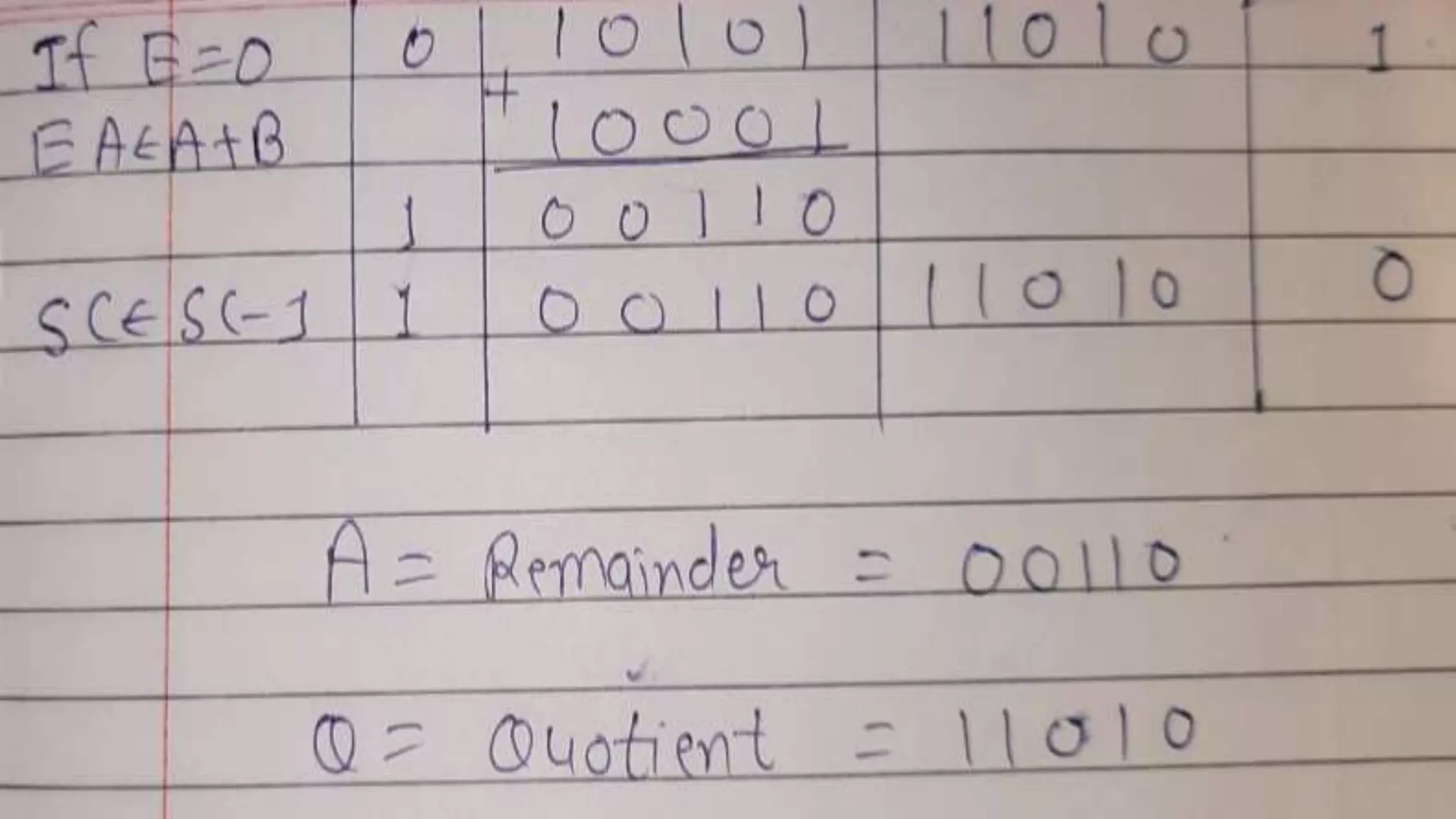
Q.3 Show the contents of registers E, A, Q, and SC during the process of division of
(a) 10100011 by 1011; (b) 00001111 by 0011. (Use a dividend of eight bits.)
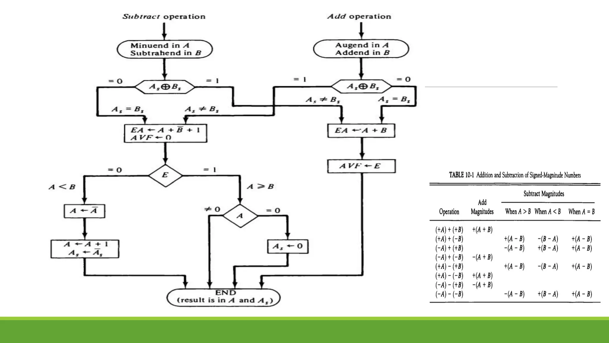
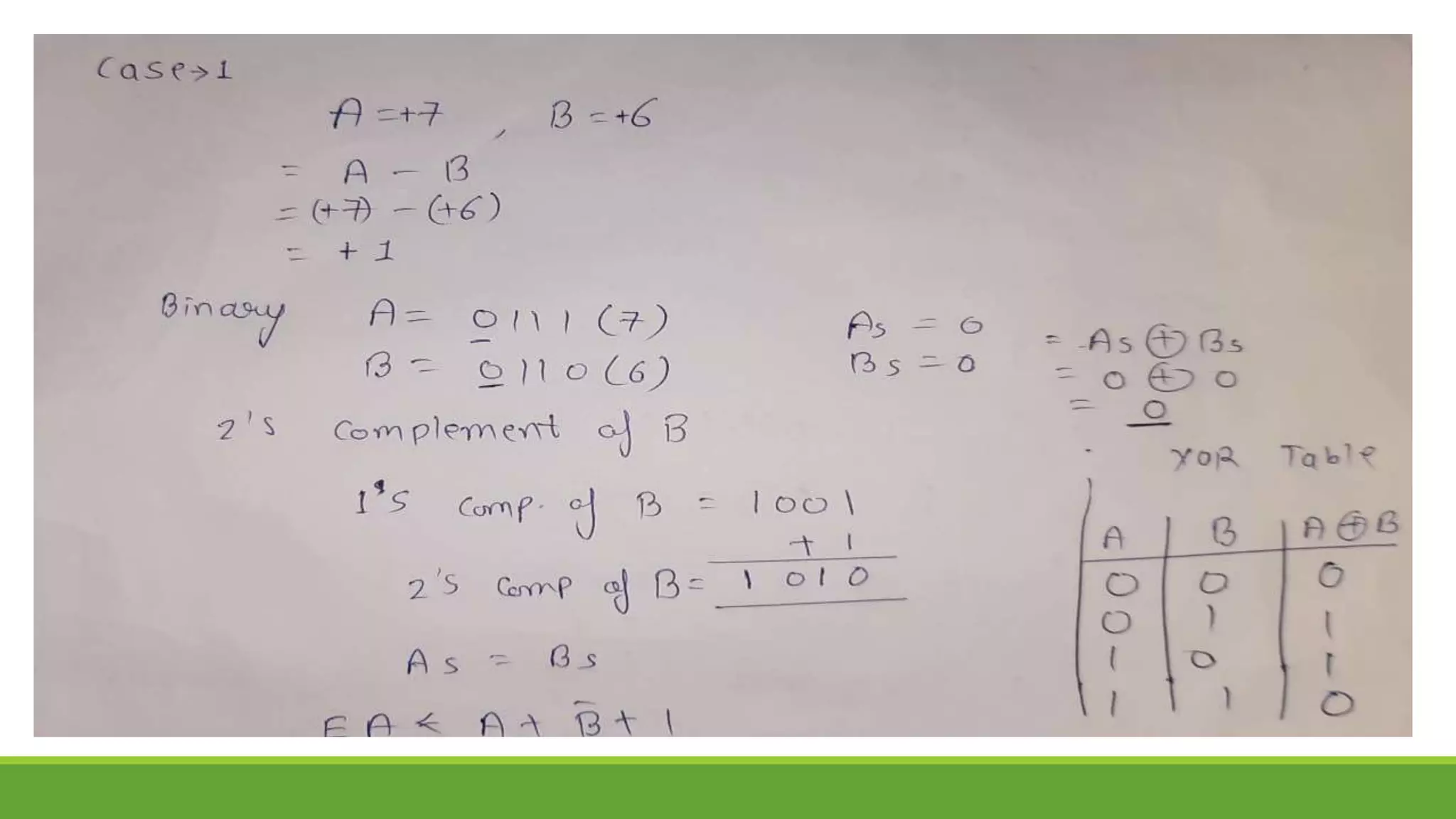
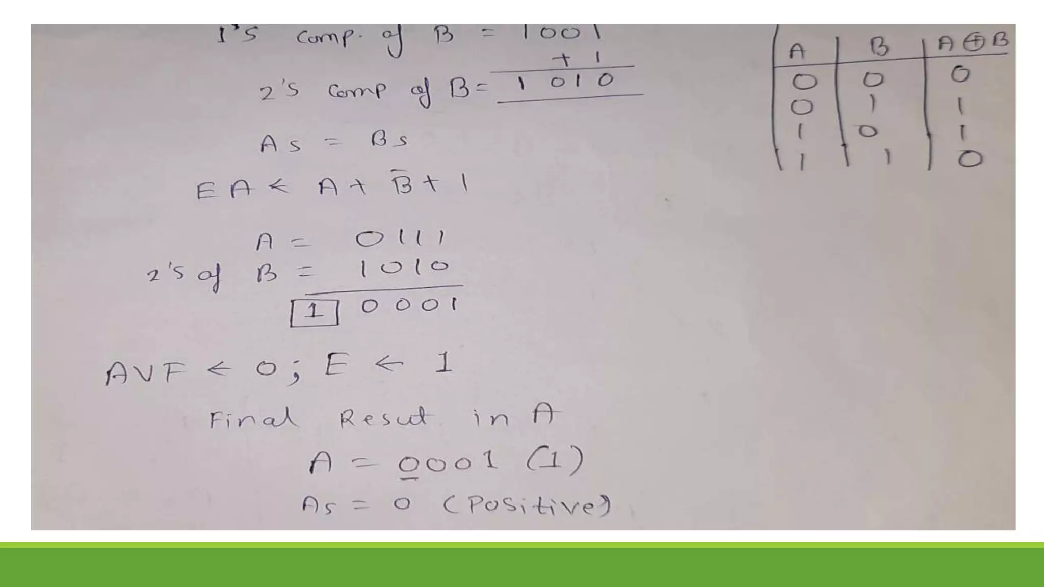
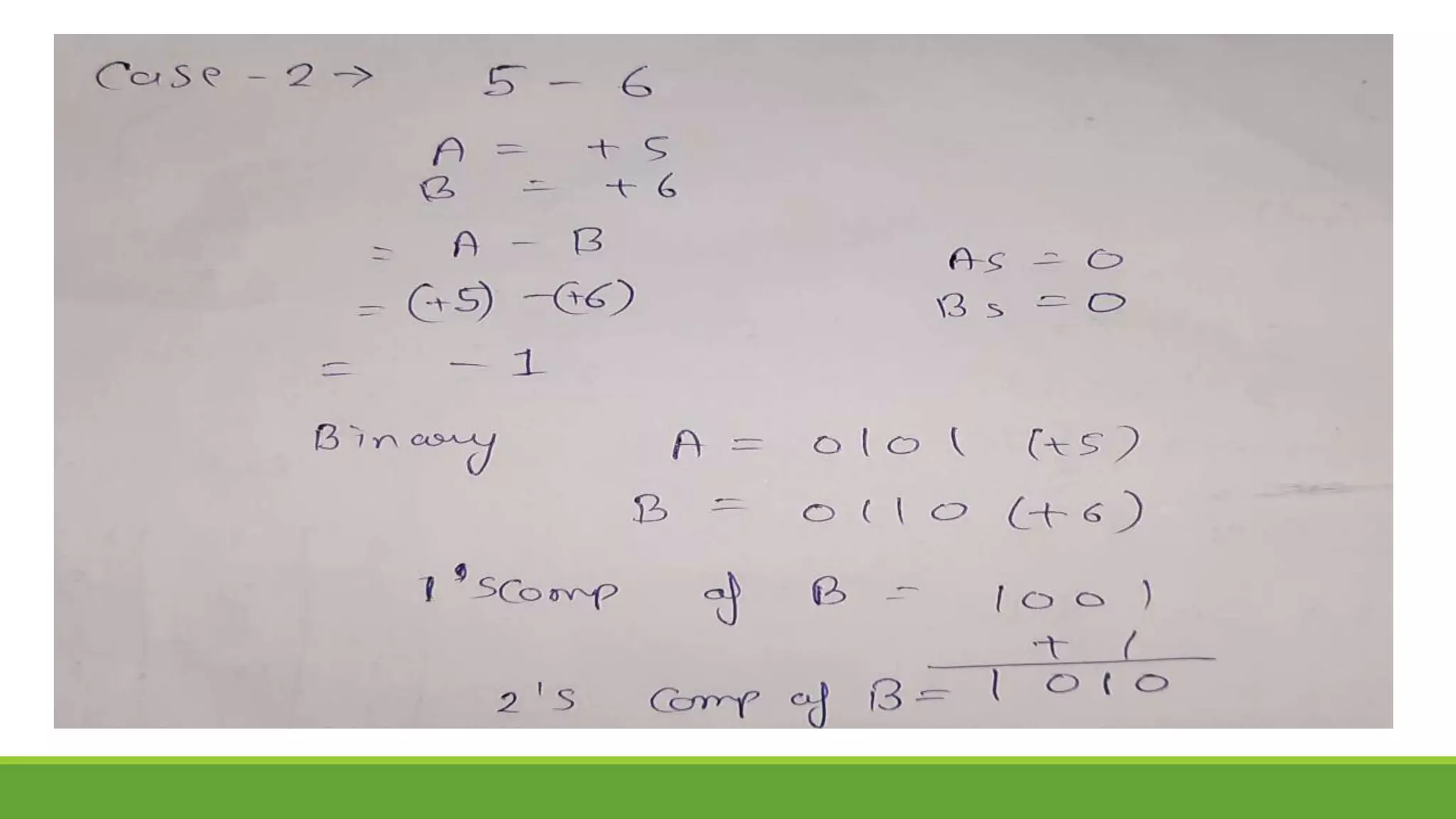
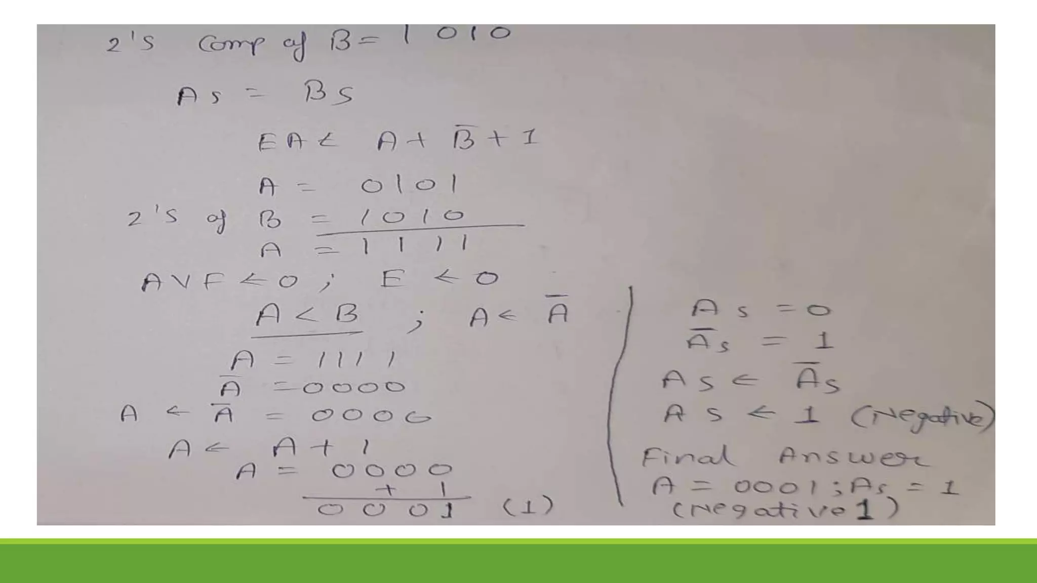
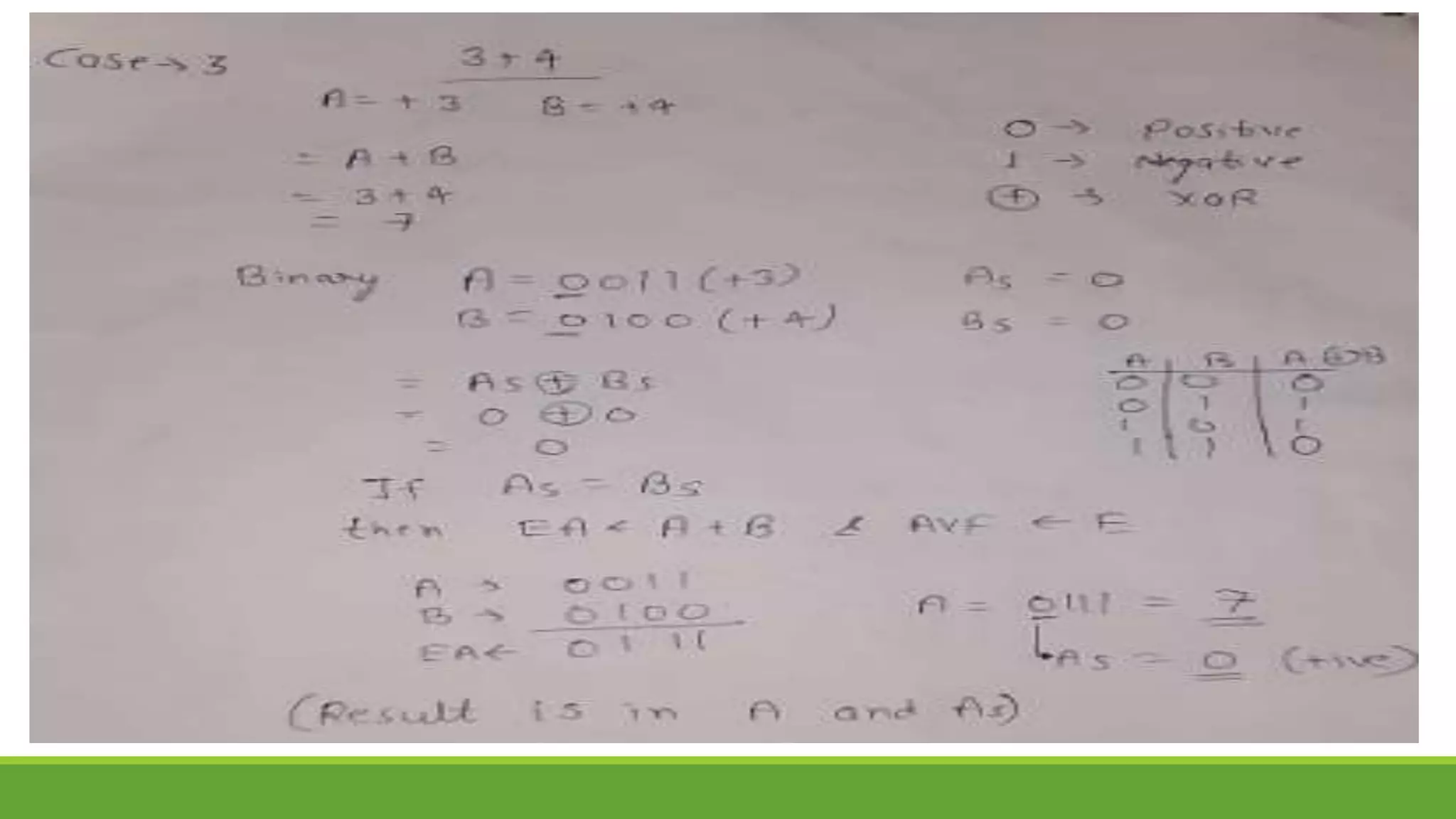
Q.4 Show the step-by-step Addition/Subtraction process using Addition/Subtraction
Algorithm
A. 8-7 B. 6-7 C. 5+4 D. -5-4
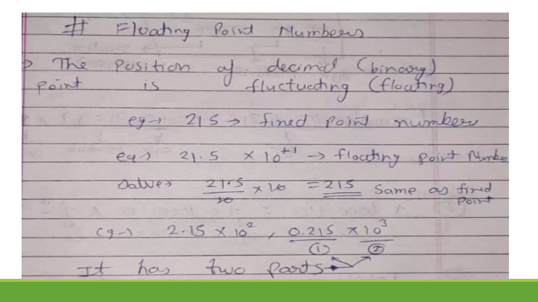
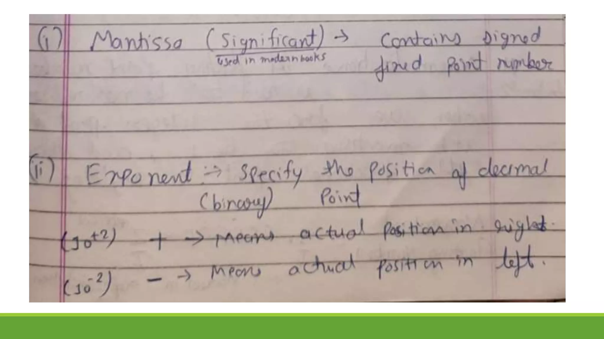
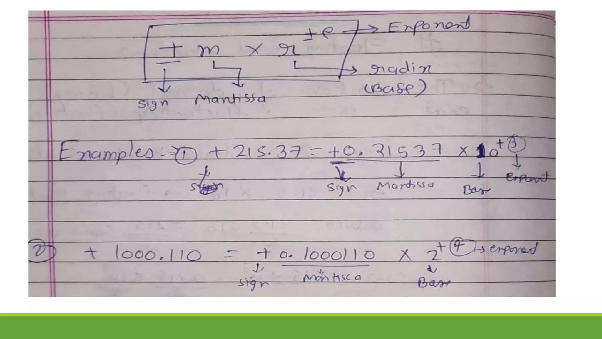
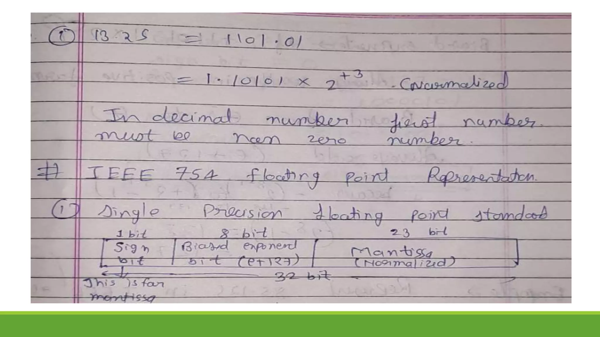
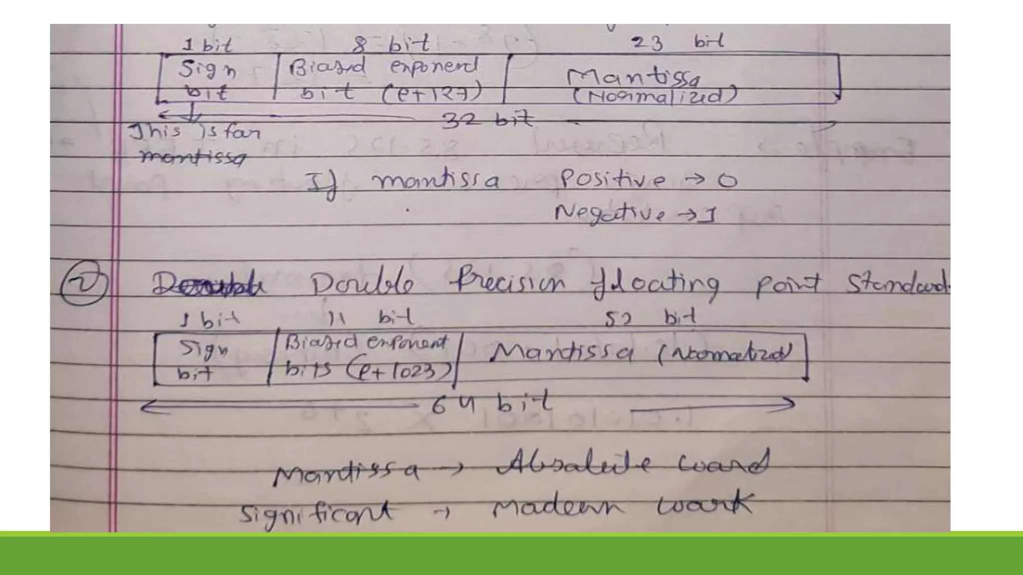
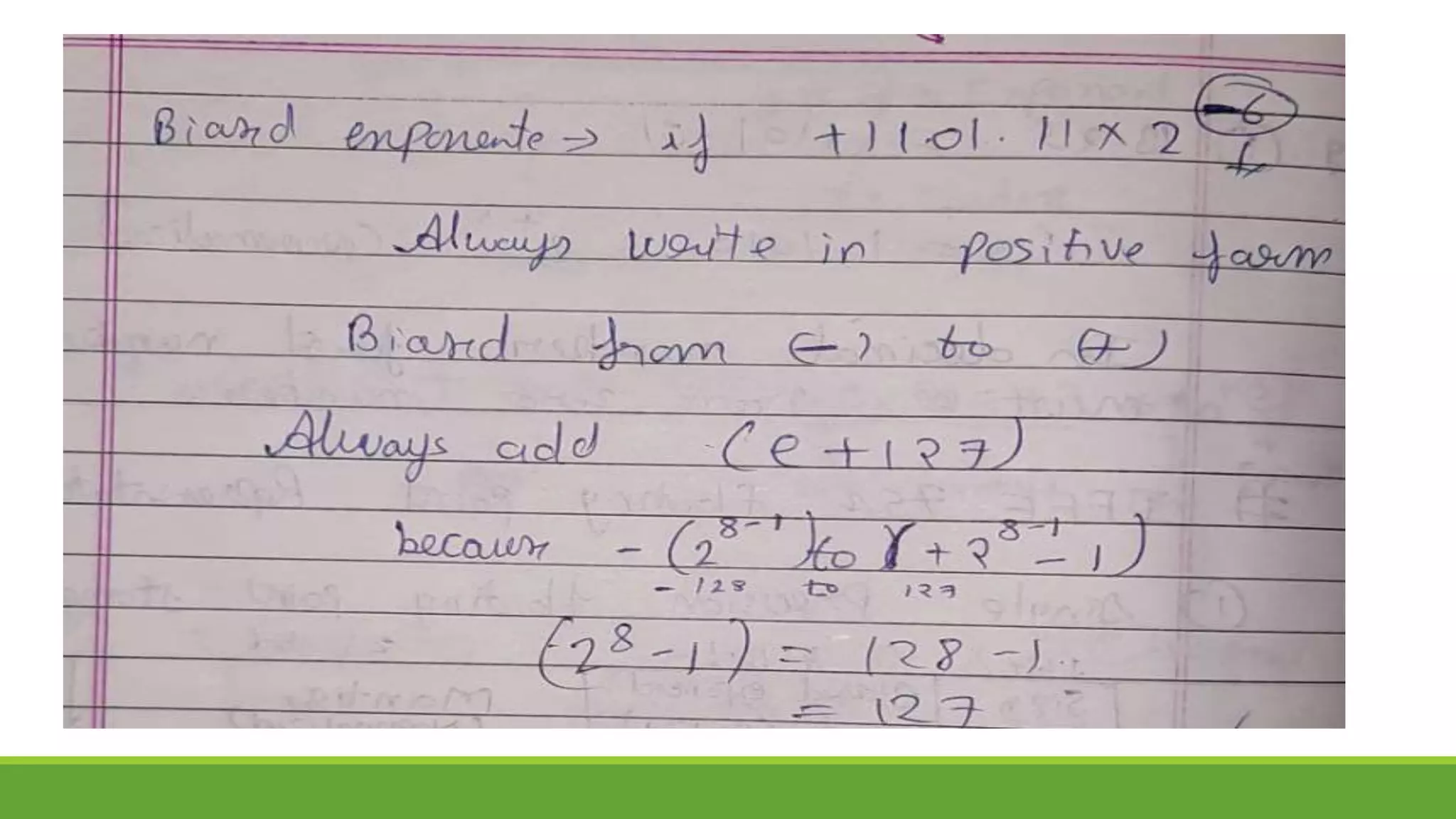
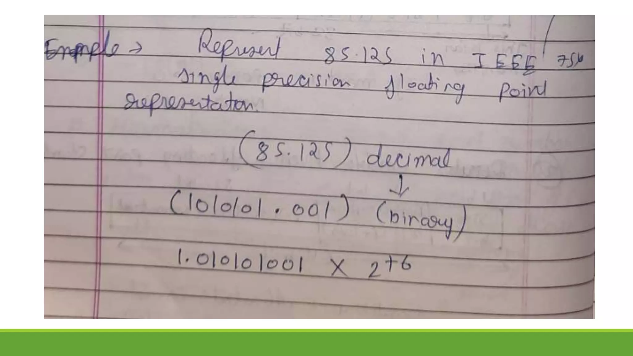
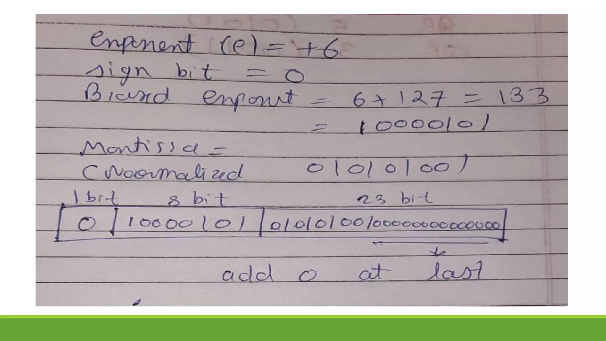
Q.5 Represent 58.25 in IEEE 754 single precision floating point representation.](https://image.slidesharecdn.com/unit-3completeppt-220413044455/75/UNIT-3-Complete-PPT-pptx-88-2048.jpg)
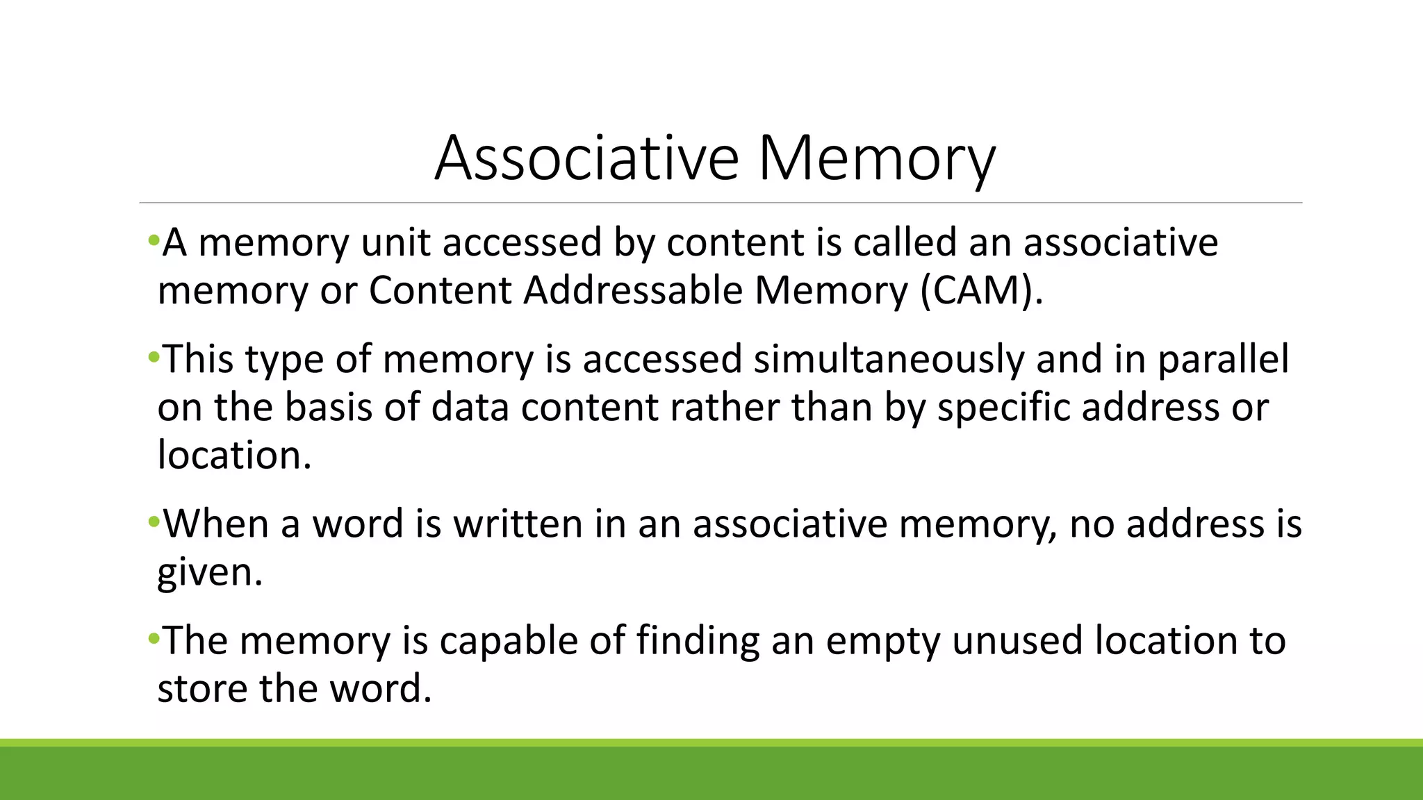
![Difference between RAM and CAM
Sr. No. Key RAM [MM] CAM [AM]
1
Definition RAM stands for Random
Access Memory.
CAM stands for Content
Addressable Memory.
2
Operation User supplies an address and
RAM returns the word present
at that location.
User supplies a word and
CAM returns the links where
word is present.
3
Cost RAM is cheaper than
associative memory.
CAM is costlier.
4
Application RAM is used to run programs
and to store their data during
execution.
CAM is primary used in
database management
systems.
5
Suitability RAM is suitable for PRAM
(Paraller RAM) algorithm.
CAM is suitable for parallel
access.](https://image.slidesharecdn.com/unit-3completeppt-220413044455/75/UNIT-3-Complete-PPT-pptx-155-2048.jpg)