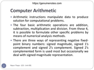
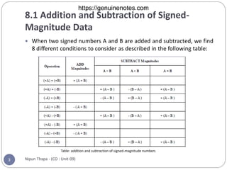
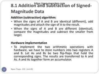
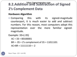
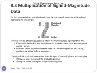
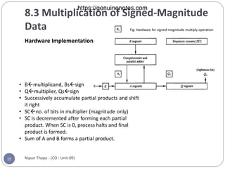
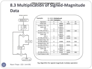
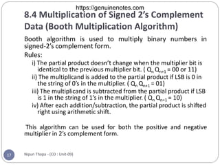
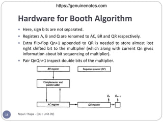
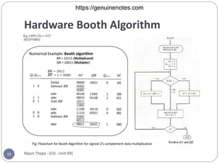
Nipun Thapa
Chapter 8
Computer Arithmetic
https://genuinenotes.com
Computer Arithmetic
Nipun Thapa - (CO : Unit-09)
2
 Arithmetic instructions manipulate data to produce
solution for computational problems.
 The four basic arithmetic operations are addition,
subtraction, multiplication and division. From these 4,
it is possible to formulate other specific problems by
means of numerical analysis methods.
 There are three ways of representing negative fixed-
point binary numbers: signed magnitude, signed 1’s
complement and signed 2’s complement. Signed 2’s
complemented form is used most but occasionally we
deal with signed magnitude representation.
https://genuinenotes.com
8.1 Addition and Subtraction of Signed-
Magnitude Data
Nipun Thapa - (CO : Unit-09)
3
 When two signed numbers A and B are added and subtracted, we find
8 different conditions to consider as described in the following table:
Table: addition and subtraction of signed-magnitude numbers
https://genuinenotes.com
8.1 Addition and Subtraction of Signed-
Magnitude Data
Nipun Thapa - (CO : Unit-09)
4
Addition (subtraction) algorithm:
 When the signs of A and B are identical (different), add
magnitudes and attach the sign of A to the result.
 When the signs of A and B are different (identical),
compare the magnitudes and subtract the smaller from
larger.
Hardware implementation
 To implement the two arithmetic operations with
hardware, we have to store numbers into two registers A
and B. Let As and Bs be two flip-flops that hold the
corresponding signs. The results are transferred to A and
As. A and As together form an accumulator.
https://genuinenotes.com
8.1 Addition and Subtraction of Signed-
Magnitude Data
Nipun Thapa - (CO : Unit-09)
5
Fig: Hardware for signed-magnitude data addition and subtraction
https://genuinenotes.com
8.1 Addition and Subtraction of Signed-
Magnitude Data
Nipun Thapa - (CO : Unit-09)
6
We need:
 Two registers A and B and sign flip-flops As and Bs
 A magnitude comparator: to check if A>B, A<B, or A=B
 A parallel adder: to perform A+B
 Two parallel subtractions: for A-B and B-A
 The sign relationships are determined from an X-OR gate with As and Bs as inputs.
Block Diagram Description
 Hardware above consists of registers A and B and sign flip-flops As and Bs.
 The complementary provides an output of B or B’ depending on mode input M.
 When M=0, the output of B is transferred to the adder, the input carry is 0 and thus
output of adder is A+B. Output carry is transferred to flip-flop E, where it can be checked
to determine overflow. When E=1, it is overflow, otherwise, not. The E=1 is transferred
to the AVF (add-overflow-flip-flop) which holds the overflow bit when A ns B are added.
 When M=1, 1’s complement of B is applied to the adder, input carry is 1 and output is
S=A+B’+1 (i.e. A-B). Output carry is transferred to flip-flop E, where it can be checked to
determine the relative magnitude of two numbers.
https://genuinenotes.com
8.1 Addition and Subtraction of Signed-
Magnitude Data
Nipun Thapa - (CO : Unit-09)
7
Hardware Algorithm
 The flowchart for the hardware algorithm is given below:
 As and Bs are compared by an X-OR gate. If output=0, signs are identical, if
1, signs are different.
 For add operation, identical signs dictate addition of magnitudes. For
subtraction, different signs dictate magnitudes be added.
 Magnitudes are with a micro operation E A A+B (E A is register that combines
E and A). If E=1, overflow occurs and is transferred to AVF.
 Two magnitudes are subtracted if signs are different for add operation and
identical for subtract operation.
 Magnitudes are subtracted with a micro operation E A A+B’+1.
 No overflow occurs if the numbers are subtracted, so AVF is cleared to 0.
 If E=1, it indicates A≥B and the result in A is correct. If the number in A is 0, the
sign As must be made positive (As=0) to avoid negative zero.
 If E=0, it indicates that A<B for which it is necessary to take 2’s complement of
value in A. the micro operation is A A’+1. The sign of As must be sign of Bs
(i.e. AsAs’).
https://genuinenotes.com
Nipun Thapa - (CO : Unit-09)
8
Fig: Flowchart for add and subtract operations with signed-magnitude data
https://genuinenotes.com
8.2.Addition and Subtraction of Signed
2’s Complement Data
Nipun Thapa - (CO : Unit-09)
9
 In signed 2’s complement representation, the leftmost bit
represents sign (0 for positive and 1 for negative). If sign
bit is 1, entire number is represented in 2’s complement
form.
 Addition: Sign bit is treated as other bits of the number.
Carry out of the sign bit is discarded.
 Subtraction: It consists of first taking 2’s complement of
subtrahend and then adding it to minuend. When two
numbers of n-digit each are added, the sum occupies n+1
bits. Overflow occurs which is detected by applying last
two carries out of the addition to XOR gate. The overflow
occurs only if output of the gate is 1.
https://genuinenotes.com
8.2.Addition and Subtraction of Signed
2’s Complement Data
Nipun Thapa - (CO : Unit-09)
10
Hardware Implementation
Fig: Hardware for signed-2’s complement data addition and subtraction
https://genuinenotes.com
8.2.Addition and Subtraction of Signed
2’s Complement Data
Nipun Thapa - (CO : Unit-09)
11
Hardware Implementation..
 Register configuration is same as signed-magnitude
representation except sign bits are not separated. The
leftmost bits in AC and BR represent sign bits.
 Significant Difference: Sign bits are added together
with the other bits in complementer and parallel
adder. The overflow flip-flop V is set to 1 if there is an
overflow. Output carry in this case is discarded.
https://genuinenotes.com
8.2.Addition and Subtraction of Signed
2’s Complement Data
Nipun Thapa - (CO : Unit-09)
12
Hardware Algorithm
Fig: Algorithm for signed-2’s complement data addition and subtraction
https://genuinenotes.com
8.2.Addition and Subtraction of Signed
2’s Complement Data
Nipun Thapa - (CO : Unit-09)
13
Hardware Algorithm
 Comparing this with its signed-magnitude
counterpart, it is much easier to add and subtract
numbers. For this reason, most computers adopt this
representation over the more familiar signed-
magnitude.
Example: 33+(-35)
AC = 33 = 00100001
BR = -35 = 2’s complement of 35 = 11011101
AC+BR = 11111110 = -2
https://genuinenotes.com
8.3 Multiplication of Signed-Magnitude
Data
Nipun Thapa - (CO : Unit-09)
14
For this representation, multiplication is done by a process of successive shift and adds
operations. As an example:
Process consists of looking successive bits of the multiplier, least significant bits first.
• If the multiplier bit is 1, the multiplicand bit is copied down; otherwise zeroes are
copied down.
• Numbers copies down in successive lines are shifted one position left. Finally,
numbers are added to form a product.
The sign of the product is determined from the signs of the multiplicand and multiplier.
• If they are alike, the sign of the product is positive.
• If they are unlike, the sign of the product is negative.
https://genuinenotes.com
8.3 Multiplication of Signed-Magnitude
Data
Nipun Thapa - (CO : Unit-09)
15
Hardware Implementation
• Bmultiplicand, Bssign
• Qmultiplier, Qssign
• Successively accumulate partial products and shift
it right
• SCno. of bits in multiplier (magnitude only)
• SC is decremented after forming each partial
product. When SC is 0, process halts and final
product is formed.
• Sum of A and B forms a partial product.
Fig: Hardware for signed-magnitude multiply operation
https://genuinenotes.com
8.3 Multiplication of Signed-Magnitude
Data
Nipun Thapa - (CO : Unit-09)
16
Fig: Algorithm for signed-magnitude multiply operation
https://genuinenotes.com
8.4 Multiplication of Signed 2’s Complement
Data (Booth Multiplication Algorithm)
Nipun Thapa - (CO : Unit-09)
17
Booth algorithm is used to multiply binary numbers in
signed-2’s complement form.
Rules:
i) The partial product doesn’t change when the multiplier bit is
identical to the previous multiplier bit. ( Qn Qn+1 = 00 or 11)
ii) The multiplicand is added to the partial product if LSB is 0 in
the string of 0’s in the multiplier. ( Qn Qn+1 = 01)
iii) The multiplicand is subtracted from the partial product if LSB
is 1 in the string of 1’s in the multiplier. ( Qn Qn+1 = 10)
iv) After each addition/subtraction, the partial product is shifted
right using arithmetic shift.
This algorithm can be used for both the positive and negative
multiplier in 2’s complement form.
https://genuinenotes.com
Hardware for Booth Algorithm
Nipun Thapa - (CO : Unit-09)
18
 Here, sign bits are not separated.
 Registers A, B and Q are renamed to AC, BR and QR respectively.
 Extra flip-flop Qn+1 appended to QR is needed to store almost lost
right shifted bit to the multiplier (which along with current Qn gives
information about bit sequencing of multiplier).
 Pair QnQn+1 inspect double bits of the multiplier.
https://genuinenotes.com
Hardware Booth Algorithm
Nipun Thapa - (CO : Unit-09)
19
Fig: Flowchart for Booth Algorithm for signed-2’s complement data multiplication
https://genuinenotes.com
Finished
Unit 8
Nipun Thapa - (CO : Unit-09)
20
https://genuinenotes.com
Nipun Thapa - (CO : Unit-09)
21
https://genuinenotes.com
Nipun Thapa - (CO : Unit-09)
22
https://genuinenotes.com
Nipun Thapa - (CO : Unit-09)
23
https://genuinenotes.com
Nipun Thapa - (CO : Unit-09)
24
https://genuinenotes.com
Nipun Thapa - (CO : Unit-09)
25
https://genuinenotes.com

Unit-8-Computer-Arithmetic.pdf

  • 1.
    Nipun Thapa Chapter 8 ComputerArithmetic https://genuinenotes.com
  • 2.
    Computer Arithmetic Nipun Thapa- (CO : Unit-09) 2  Arithmetic instructions manipulate data to produce solution for computational problems.  The four basic arithmetic operations are addition, subtraction, multiplication and division. From these 4, it is possible to formulate other specific problems by means of numerical analysis methods.  There are three ways of representing negative fixed- point binary numbers: signed magnitude, signed 1’s complement and signed 2’s complement. Signed 2’s complemented form is used most but occasionally we deal with signed magnitude representation. https://genuinenotes.com
  • 3.
    8.1 Addition andSubtraction of Signed- Magnitude Data Nipun Thapa - (CO : Unit-09) 3  When two signed numbers A and B are added and subtracted, we find 8 different conditions to consider as described in the following table: Table: addition and subtraction of signed-magnitude numbers https://genuinenotes.com
  • 4.
    8.1 Addition andSubtraction of Signed- Magnitude Data Nipun Thapa - (CO : Unit-09) 4 Addition (subtraction) algorithm:  When the signs of A and B are identical (different), add magnitudes and attach the sign of A to the result.  When the signs of A and B are different (identical), compare the magnitudes and subtract the smaller from larger. Hardware implementation  To implement the two arithmetic operations with hardware, we have to store numbers into two registers A and B. Let As and Bs be two flip-flops that hold the corresponding signs. The results are transferred to A and As. A and As together form an accumulator. https://genuinenotes.com
  • 5.
    8.1 Addition andSubtraction of Signed- Magnitude Data Nipun Thapa - (CO : Unit-09) 5 Fig: Hardware for signed-magnitude data addition and subtraction https://genuinenotes.com
  • 6.
    8.1 Addition andSubtraction of Signed- Magnitude Data Nipun Thapa - (CO : Unit-09) 6 We need:  Two registers A and B and sign flip-flops As and Bs  A magnitude comparator: to check if A>B, A<B, or A=B  A parallel adder: to perform A+B  Two parallel subtractions: for A-B and B-A  The sign relationships are determined from an X-OR gate with As and Bs as inputs. Block Diagram Description  Hardware above consists of registers A and B and sign flip-flops As and Bs.  The complementary provides an output of B or B’ depending on mode input M.  When M=0, the output of B is transferred to the adder, the input carry is 0 and thus output of adder is A+B. Output carry is transferred to flip-flop E, where it can be checked to determine overflow. When E=1, it is overflow, otherwise, not. The E=1 is transferred to the AVF (add-overflow-flip-flop) which holds the overflow bit when A ns B are added.  When M=1, 1’s complement of B is applied to the adder, input carry is 1 and output is S=A+B’+1 (i.e. A-B). Output carry is transferred to flip-flop E, where it can be checked to determine the relative magnitude of two numbers. https://genuinenotes.com
  • 7.
    8.1 Addition andSubtraction of Signed- Magnitude Data Nipun Thapa - (CO : Unit-09) 7 Hardware Algorithm  The flowchart for the hardware algorithm is given below:  As and Bs are compared by an X-OR gate. If output=0, signs are identical, if 1, signs are different.  For add operation, identical signs dictate addition of magnitudes. For subtraction, different signs dictate magnitudes be added.  Magnitudes are with a micro operation E A A+B (E A is register that combines E and A). If E=1, overflow occurs and is transferred to AVF.  Two magnitudes are subtracted if signs are different for add operation and identical for subtract operation.  Magnitudes are subtracted with a micro operation E A A+B’+1.  No overflow occurs if the numbers are subtracted, so AVF is cleared to 0.  If E=1, it indicates A≥B and the result in A is correct. If the number in A is 0, the sign As must be made positive (As=0) to avoid negative zero.  If E=0, it indicates that A<B for which it is necessary to take 2’s complement of value in A. the micro operation is A A’+1. The sign of As must be sign of Bs (i.e. AsAs’). https://genuinenotes.com
  • 8.
    Nipun Thapa -(CO : Unit-09) 8 Fig: Flowchart for add and subtract operations with signed-magnitude data https://genuinenotes.com
  • 9.
    8.2.Addition and Subtractionof Signed 2’s Complement Data Nipun Thapa - (CO : Unit-09) 9  In signed 2’s complement representation, the leftmost bit represents sign (0 for positive and 1 for negative). If sign bit is 1, entire number is represented in 2’s complement form.  Addition: Sign bit is treated as other bits of the number. Carry out of the sign bit is discarded.  Subtraction: It consists of first taking 2’s complement of subtrahend and then adding it to minuend. When two numbers of n-digit each are added, the sum occupies n+1 bits. Overflow occurs which is detected by applying last two carries out of the addition to XOR gate. The overflow occurs only if output of the gate is 1. https://genuinenotes.com
  • 10.
    8.2.Addition and Subtractionof Signed 2’s Complement Data Nipun Thapa - (CO : Unit-09) 10 Hardware Implementation Fig: Hardware for signed-2’s complement data addition and subtraction https://genuinenotes.com
  • 11.
    8.2.Addition and Subtractionof Signed 2’s Complement Data Nipun Thapa - (CO : Unit-09) 11 Hardware Implementation..  Register configuration is same as signed-magnitude representation except sign bits are not separated. The leftmost bits in AC and BR represent sign bits.  Significant Difference: Sign bits are added together with the other bits in complementer and parallel adder. The overflow flip-flop V is set to 1 if there is an overflow. Output carry in this case is discarded. https://genuinenotes.com
  • 12.
    8.2.Addition and Subtractionof Signed 2’s Complement Data Nipun Thapa - (CO : Unit-09) 12 Hardware Algorithm Fig: Algorithm for signed-2’s complement data addition and subtraction https://genuinenotes.com
  • 13.
    8.2.Addition and Subtractionof Signed 2’s Complement Data Nipun Thapa - (CO : Unit-09) 13 Hardware Algorithm  Comparing this with its signed-magnitude counterpart, it is much easier to add and subtract numbers. For this reason, most computers adopt this representation over the more familiar signed- magnitude. Example: 33+(-35) AC = 33 = 00100001 BR = -35 = 2’s complement of 35 = 11011101 AC+BR = 11111110 = -2 https://genuinenotes.com
  • 14.
    8.3 Multiplication ofSigned-Magnitude Data Nipun Thapa - (CO : Unit-09) 14 For this representation, multiplication is done by a process of successive shift and adds operations. As an example: Process consists of looking successive bits of the multiplier, least significant bits first. • If the multiplier bit is 1, the multiplicand bit is copied down; otherwise zeroes are copied down. • Numbers copies down in successive lines are shifted one position left. Finally, numbers are added to form a product. The sign of the product is determined from the signs of the multiplicand and multiplier. • If they are alike, the sign of the product is positive. • If they are unlike, the sign of the product is negative. https://genuinenotes.com
  • 15.
    8.3 Multiplication ofSigned-Magnitude Data Nipun Thapa - (CO : Unit-09) 15 Hardware Implementation • Bmultiplicand, Bssign • Qmultiplier, Qssign • Successively accumulate partial products and shift it right • SCno. of bits in multiplier (magnitude only) • SC is decremented after forming each partial product. When SC is 0, process halts and final product is formed. • Sum of A and B forms a partial product. Fig: Hardware for signed-magnitude multiply operation https://genuinenotes.com
  • 16.
    8.3 Multiplication ofSigned-Magnitude Data Nipun Thapa - (CO : Unit-09) 16 Fig: Algorithm for signed-magnitude multiply operation https://genuinenotes.com
  • 17.
    8.4 Multiplication ofSigned 2’s Complement Data (Booth Multiplication Algorithm) Nipun Thapa - (CO : Unit-09) 17 Booth algorithm is used to multiply binary numbers in signed-2’s complement form. Rules: i) The partial product doesn’t change when the multiplier bit is identical to the previous multiplier bit. ( Qn Qn+1 = 00 or 11) ii) The multiplicand is added to the partial product if LSB is 0 in the string of 0’s in the multiplier. ( Qn Qn+1 = 01) iii) The multiplicand is subtracted from the partial product if LSB is 1 in the string of 1’s in the multiplier. ( Qn Qn+1 = 10) iv) After each addition/subtraction, the partial product is shifted right using arithmetic shift. This algorithm can be used for both the positive and negative multiplier in 2’s complement form. https://genuinenotes.com
  • 18.
    Hardware for BoothAlgorithm Nipun Thapa - (CO : Unit-09) 18  Here, sign bits are not separated.  Registers A, B and Q are renamed to AC, BR and QR respectively.  Extra flip-flop Qn+1 appended to QR is needed to store almost lost right shifted bit to the multiplier (which along with current Qn gives information about bit sequencing of multiplier).  Pair QnQn+1 inspect double bits of the multiplier. https://genuinenotes.com
  • 19.
    Hardware Booth Algorithm NipunThapa - (CO : Unit-09) 19 Fig: Flowchart for Booth Algorithm for signed-2’s complement data multiplication https://genuinenotes.com
  • 20.
    Finished Unit 8 Nipun Thapa- (CO : Unit-09) 20 https://genuinenotes.com
  • 21.
    Nipun Thapa -(CO : Unit-09) 21 https://genuinenotes.com
  • 22.
    Nipun Thapa -(CO : Unit-09) 22 https://genuinenotes.com
  • 23.
    Nipun Thapa -(CO : Unit-09) 23 https://genuinenotes.com
  • 24.
    Nipun Thapa -(CO : Unit-09) 24 https://genuinenotes.com
  • 25.
    Nipun Thapa -(CO : Unit-09) 25 https://genuinenotes.com