Downloaded 388 times


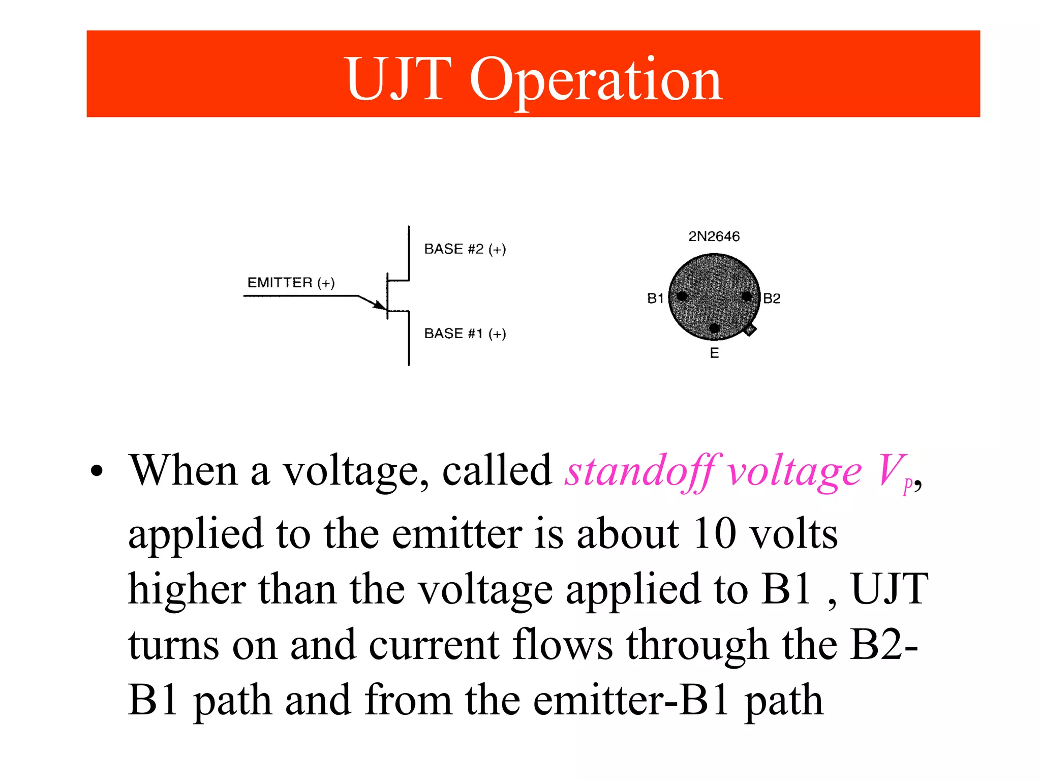


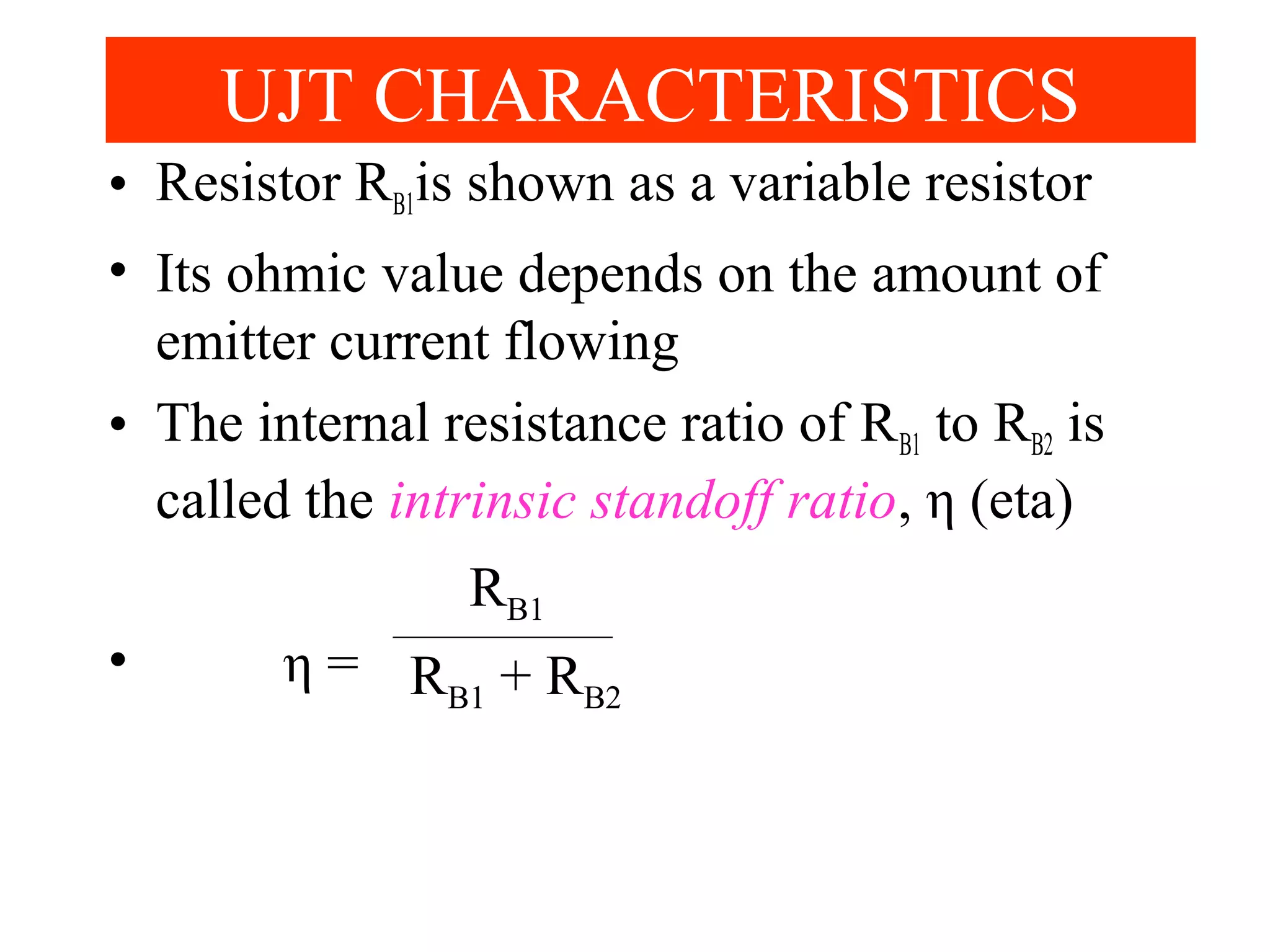


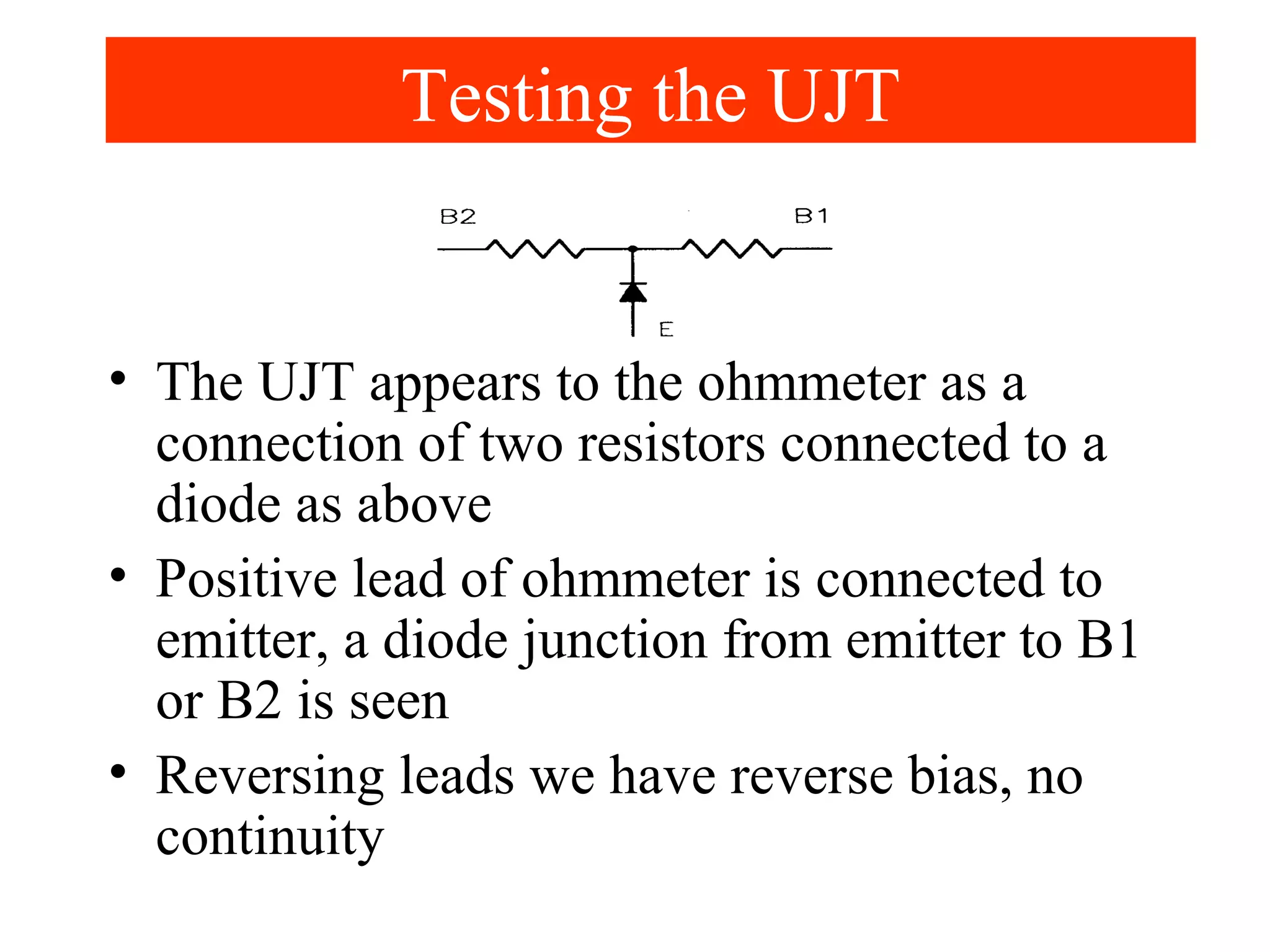


The unijunction transistor (UJT) is a breakover-type switching device used in applications like timers and oscillators, featuring two bases and one emitter for current flow control. It operates by turning on when the emitter voltage exceeds the standoff voltage, allowing current to flow until the voltage drops below a certain point. The UJT's performance is characterized by its resistance properties and the intrinsic standoff ratio, which influences the required emitter voltage for switching.


