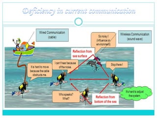
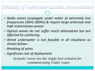
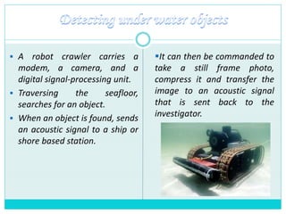
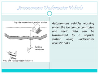
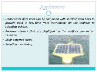
Made by-
Digisha Singhal 13bec026
Kinjal Aggrawal 13bec054
Guided by-
Dr. Mehul Naik
1. Deficiency in current communication
2. Necessity of underwater acoustic communication
3. Acoustic communication
4. Basic acoustic communication model
5. Acoustic modem
6. Applications
7. Limitations
8. Conclusion
9. References
 Radio waves propagate under water at extremely low
frequencies (30Hz-300Hz) & require large antennae and
high transmission power.
 Optical waves do not suffer much attenuation but are
affected by scattering.
 Wired underwater is not feasible in all situations as
shown below-:
o Breaking of wires
o Significant cost of deployment
Acoustic waves are the single best solution for
communicating Under water.
 Underwater Acoustics is the study of propagation of sound in water
& interaction of mechanical waves that constitute with water & its
boundaries.
 Underwater wireless communication is the wireless communication
in which acoustic signals (waves) carry digital information through
an underwater channel.
 Typical frequencies associated with Underwater Acoustics are 10Hz
to 1MHz.
 The propagation of sound in the ocean at frequencies lower than
10 Hz is not possible.
 Frequencies above 1 MHz are rarely used because they are
absorbed very quickly.
 When no data is being transmitted, the modem stays in sleep
mode, it periodically wakes up to receive possible data being
transmitted by far end modem. This results in low power
consumption.
 Similarly when the data is to be transmitted , the modem receives
data from its link in sleep mode and then switches to transmit
mode and transmit the data.
 This technology can also be used to control small, unmanned
submarines, called Autonomous Undersea Vehicles (AUV's).
 Oceanographers use acoustics to control underwater instruments
and acquire the data that they collect remotely.
 Underwater acoustic modems are relatively slow compared to
telephone or cable modems on land.
 Equipment
 Autonomous Undersea Vehicles (AUVs)
 Underwater sensors (UW-ASN)
 A robot crawler carries a
modem, a camera, and a
digital signal-processing unit.
 Traversing the seafloor,
searches for an object.
 When an object is found, sends
an acoustic signal to a ship or
shore based station.
It can then be commanded to
take a still frame photo,
compress it and transfer the
image to an acoustic signal
that is sent back to the
investigator.
Autonomous vehicles working
under the ice can be controlled
and their data can be
transmitted to a topside
station using underwater
acoustic links.
 Underwater data links can be combined with satellite data links to
provide data in real-time from instruments on the seafloor to
scientists ashore.
 Pressure sensors that are deployed on the seafloor can detect
tsunamis.
 Solar powered AUVs.
 Pollution monitoring.
 Battery power is limited and usually batteries cannot be recharged
easily.
 The available bandwidth is severely limited.
 Underwater sensors are prone to failures because of fouling,
corrosion, etc.
 Highly affected by environmental and natural factors such as
heterogeneities of the water column, variations of sound velocity
versus depth, temperature and salinity, multiple and random sea
reflections and significant scattering by fish and bubble clouds.
The main objective is to overcome the present limitations and
implement advanced technology for oceanographic research and
cope up with the environmental effects on the noise performance
of acoustic systems to compete with the future challenges like
effective transmission of audio and video signals etc.
1. www.ieee.org/organizations/pubs/newsletters/oes/html/spring06
/underwater.html
2. www.link-quest.com/html/oceans2000.pdf/
3. www.gleonrcn.org/pgmdownload_media.php?name=Aquanode.p
ps
4. www.cs.virginia.edu/sigbed/archives/akyildiz.pdf

Underwater acoustic 1

  • 1.
    Made by- Digisha Singhal13bec026 Kinjal Aggrawal 13bec054 Guided by- Dr. Mehul Naik
  • 2.
    1. Deficiency incurrent communication 2. Necessity of underwater acoustic communication 3. Acoustic communication 4. Basic acoustic communication model 5. Acoustic modem 6. Applications 7. Limitations 8. Conclusion 9. References
  • 4.
     Radio wavespropagate under water at extremely low frequencies (30Hz-300Hz) & require large antennae and high transmission power.  Optical waves do not suffer much attenuation but are affected by scattering.  Wired underwater is not feasible in all situations as shown below-: o Breaking of wires o Significant cost of deployment Acoustic waves are the single best solution for communicating Under water.
  • 5.
     Underwater Acousticsis the study of propagation of sound in water & interaction of mechanical waves that constitute with water & its boundaries.  Underwater wireless communication is the wireless communication in which acoustic signals (waves) carry digital information through an underwater channel.  Typical frequencies associated with Underwater Acoustics are 10Hz to 1MHz.  The propagation of sound in the ocean at frequencies lower than 10 Hz is not possible.  Frequencies above 1 MHz are rarely used because they are absorbed very quickly.
  • 7.
     When nodata is being transmitted, the modem stays in sleep mode, it periodically wakes up to receive possible data being transmitted by far end modem. This results in low power consumption.  Similarly when the data is to be transmitted , the modem receives data from its link in sleep mode and then switches to transmit mode and transmit the data.  This technology can also be used to control small, unmanned submarines, called Autonomous Undersea Vehicles (AUV's).
  • 8.
     Oceanographers useacoustics to control underwater instruments and acquire the data that they collect remotely.  Underwater acoustic modems are relatively slow compared to telephone or cable modems on land.  Equipment  Autonomous Undersea Vehicles (AUVs)  Underwater sensors (UW-ASN)
  • 9.
     A robotcrawler carries a modem, a camera, and a digital signal-processing unit.  Traversing the seafloor, searches for an object.  When an object is found, sends an acoustic signal to a ship or shore based station. It can then be commanded to take a still frame photo, compress it and transfer the image to an acoustic signal that is sent back to the investigator.
  • 10.
    Autonomous vehicles working underthe ice can be controlled and their data can be transmitted to a topside station using underwater acoustic links.
  • 11.
     Underwater datalinks can be combined with satellite data links to provide data in real-time from instruments on the seafloor to scientists ashore.  Pressure sensors that are deployed on the seafloor can detect tsunamis.  Solar powered AUVs.  Pollution monitoring.
  • 12.
     Battery poweris limited and usually batteries cannot be recharged easily.  The available bandwidth is severely limited.  Underwater sensors are prone to failures because of fouling, corrosion, etc.  Highly affected by environmental and natural factors such as heterogeneities of the water column, variations of sound velocity versus depth, temperature and salinity, multiple and random sea reflections and significant scattering by fish and bubble clouds.
  • 13.
    The main objectiveis to overcome the present limitations and implement advanced technology for oceanographic research and cope up with the environmental effects on the noise performance of acoustic systems to compete with the future challenges like effective transmission of audio and video signals etc.
  • 14.
    1. www.ieee.org/organizations/pubs/newsletters/oes/html/spring06 /underwater.html 2. www.link-quest.com/html/oceans2000.pdf/ 3.www.gleonrcn.org/pgmdownload_media.php?name=Aquanode.p ps 4. www.cs.virginia.edu/sigbed/archives/akyildiz.pdf