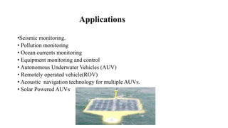
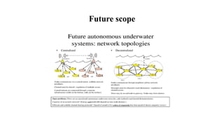
A
Technical seminar report
on
underwater wireless communication
BACHELOR OF TECHNOLOGY
IN
ELECTRONICS AND COMMUNICATION ENGINEERING
Shri A.RAJAIAH B.E,M.Tech,(Ph.D.)
Associate professor
Presented by
B.MARY ROJA (14J21A0405)
DEPARTMENT OF ELECTRONICS AND COMMUNICATION ENGINEERING
JOGINPALLY B.R. ENGINEERING COLLEGE
2017-2018
CONTENTS
INTRODUCTION
NECESSITY OF UWC
UWC TECHNOLOGY
APPLICATIONS
ADVANTAGES
DISADVANTAGES
FUTURESCOPE
CONCLUSION
REFERENCES
INTRODUCTION
Aim:
The main aim of this topic is to carry digital information through an underwater
channel are not radio signals, as electromagnetic waves propagate over short
distances. Instead acoustic waves are used which can propagate over long
distances.
Previous system:
Over the past decades, cabled submersibles were used to discover the remains of
titanic and hydrothermal vents due to the burden and cost of heavy cables that
must be used to establish a high-speed communication between the remote end
and the surface.
Proposed system:
To overcome such problems in previous system, underwater wireless
communication has come into existence.
Necessity of Underwater Wireless
Communication
Wired underwater is not feasible in all situations as shown below-:
• Temporary experiments
• Breaking of wires
• Significant cost of deployment
• Experiment over long distances.
To cope up with above situations, we require underwater wireless communication.
Underwater Wireless Communication
Technology
• Radio waves do not propagate well underwater due to the high energy absorption
of water.
• Therefore, underwater communication are based on acoustic links characterized
by large propagation delays.
• Acoustic channels have low bandwidth.
Continuation
• The signal that are used to carry digital information through an underwater
channel are acoustic channel.
• The propagation speed of acoustic signals in water is typically 1500 m/s.
• It cannot rely on the Global Positioning System (GPS).
Factors Influencing Acoustic Communication
• Path loss: Due to attenuation and geometric spreading.
• Noise: Man-made noise and ambient noise(due to hydrodynamics)
• Multi-path propogation
• High propogation delay
• Doppler frequency spread.
Hardware Platform Interfaces
• Sensor Interface:
• Must develop common interface with different sensors (chemical, optical, etc.)
and communication elements (transducer) .
• Wide (constantly changing) variety of sensors, sampling strategies
• Communication Interface:
Amplifiers, Transducers
Signal modulation
Hardware:
Software Defined Acoustic Modem (SDAM)
Reconfigurable hardware known to provide, flexible, high performance
implementations for DSP applications
Acoustic Modem
• Employ advanced modulation scheme and channel equalization for improved
signal to noise ratio.
• Employ high performance error detection and correction coding scheme which
reduces bit error rate to less than 10-7
Parts of an acoustic modem:
• DSP Board
• AFE(Analog Front End) Board
• DC/DC Converter
Data Transmission in Modem
• When no data is being transmitted, the modem stays in sleep mode, it periodically
wakes up to receive possible data being transmitted by far end modem. This
results in low power consumption. Similarly when the data is to be transmitted ,
the modem receives data from its link in sleep mode and then switches to transmit
mode and transmit the data.
Underwater Acoustic Sensor Networks (UW-ASN)
• Group of sensors and vehicles deployed underwater and networked via acoustic
links, performing collaborative tasks.
• Equipment
• Autonomous Underwater Vehicles (AUVs)
• Underwater sensors (UW-ASN)
UW-ASN Communication Architecture
• 2-D ARCHITECTURE
3-D Architecture
Applications
•Seismic monitoring.
• Pollution monitoring
• Ocean currents monitoring
• Equipment monitoring and control
• Autonomous Underwater Vehicles (AUV)
• Remotely operated vehicle(ROV)
• Acoustic navigation technology for multiple AUVs.
• Solar Powered AUVs
Advantages
• Can be used to provide early warnings of tsunamis generated by undersea
earthquakes.
• It avoids data spoofing.
• It avoids privacy leakage.
• Pollution monitoring.
Disadvantages
• Battery power is limited and usually batteries cannot be recharged also because
solar energy cannot be exploited .
•
• The available bandwidth is severely limited.
• Channel characteristics including long and variable propagation delays.
• Multipath and fading problems.
• High bit error rate.
Conclusion
Despite much development in this area of the underwater wireless communication,
there is still an immense scope so more research as major part of the ocean bottom
yet remains unexploded.
The main objective is to overcome the present limitations and implement advanced
technology for oceanographic research and cope up with the environmental effects
on the noise performance of acoustic systems to compete with the future challenges
like effective transmission of audio and video signals etc.
Future scope
REFERENCES
• www.google.com
• www.wikipedia.com
• www.studymafia.org
THANK YOU

UNDER WATER WIRELESS COMMUNICATION

  • 1.
    A Technical seminar report on underwaterwireless communication BACHELOR OF TECHNOLOGY IN ELECTRONICS AND COMMUNICATION ENGINEERING Shri A.RAJAIAH B.E,M.Tech,(Ph.D.) Associate professor Presented by B.MARY ROJA (14J21A0405) DEPARTMENT OF ELECTRONICS AND COMMUNICATION ENGINEERING JOGINPALLY B.R. ENGINEERING COLLEGE 2017-2018
  • 2.
    CONTENTS INTRODUCTION NECESSITY OF UWC UWCTECHNOLOGY APPLICATIONS ADVANTAGES DISADVANTAGES FUTURESCOPE CONCLUSION REFERENCES
  • 3.
    INTRODUCTION Aim: The main aimof this topic is to carry digital information through an underwater channel are not radio signals, as electromagnetic waves propagate over short distances. Instead acoustic waves are used which can propagate over long distances. Previous system: Over the past decades, cabled submersibles were used to discover the remains of titanic and hydrothermal vents due to the burden and cost of heavy cables that must be used to establish a high-speed communication between the remote end and the surface. Proposed system: To overcome such problems in previous system, underwater wireless communication has come into existence.
  • 4.
    Necessity of UnderwaterWireless Communication Wired underwater is not feasible in all situations as shown below-: • Temporary experiments • Breaking of wires • Significant cost of deployment • Experiment over long distances. To cope up with above situations, we require underwater wireless communication.
  • 5.
    Underwater Wireless Communication Technology •Radio waves do not propagate well underwater due to the high energy absorption of water. • Therefore, underwater communication are based on acoustic links characterized by large propagation delays. • Acoustic channels have low bandwidth.
  • 6.
    Continuation • The signalthat are used to carry digital information through an underwater channel are acoustic channel. • The propagation speed of acoustic signals in water is typically 1500 m/s. • It cannot rely on the Global Positioning System (GPS).
  • 7.
    Factors Influencing AcousticCommunication • Path loss: Due to attenuation and geometric spreading. • Noise: Man-made noise and ambient noise(due to hydrodynamics) • Multi-path propogation • High propogation delay • Doppler frequency spread.
  • 8.
    Hardware Platform Interfaces •Sensor Interface: • Must develop common interface with different sensors (chemical, optical, etc.) and communication elements (transducer) . • Wide (constantly changing) variety of sensors, sampling strategies • Communication Interface: Amplifiers, Transducers Signal modulation Hardware: Software Defined Acoustic Modem (SDAM) Reconfigurable hardware known to provide, flexible, high performance implementations for DSP applications
  • 9.
    Acoustic Modem • Employadvanced modulation scheme and channel equalization for improved signal to noise ratio. • Employ high performance error detection and correction coding scheme which reduces bit error rate to less than 10-7 Parts of an acoustic modem: • DSP Board • AFE(Analog Front End) Board • DC/DC Converter
  • 10.
    Data Transmission inModem • When no data is being transmitted, the modem stays in sleep mode, it periodically wakes up to receive possible data being transmitted by far end modem. This results in low power consumption. Similarly when the data is to be transmitted , the modem receives data from its link in sleep mode and then switches to transmit mode and transmit the data.
  • 11.
    Underwater Acoustic SensorNetworks (UW-ASN) • Group of sensors and vehicles deployed underwater and networked via acoustic links, performing collaborative tasks. • Equipment • Autonomous Underwater Vehicles (AUVs) • Underwater sensors (UW-ASN)
  • 12.
  • 13.
  • 14.
    Applications •Seismic monitoring. • Pollutionmonitoring • Ocean currents monitoring • Equipment monitoring and control • Autonomous Underwater Vehicles (AUV) • Remotely operated vehicle(ROV) • Acoustic navigation technology for multiple AUVs. • Solar Powered AUVs
  • 15.
    Advantages • Can beused to provide early warnings of tsunamis generated by undersea earthquakes. • It avoids data spoofing. • It avoids privacy leakage. • Pollution monitoring.
  • 16.
    Disadvantages • Battery poweris limited and usually batteries cannot be recharged also because solar energy cannot be exploited . • • The available bandwidth is severely limited. • Channel characteristics including long and variable propagation delays. • Multipath and fading problems. • High bit error rate.
  • 17.
    Conclusion Despite much developmentin this area of the underwater wireless communication, there is still an immense scope so more research as major part of the ocean bottom yet remains unexploded. The main objective is to overcome the present limitations and implement advanced technology for oceanographic research and cope up with the environmental effects on the noise performance of acoustic systems to compete with the future challenges like effective transmission of audio and video signals etc.
  • 18.
  • 19.
  • 20.