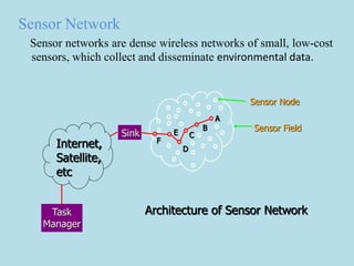
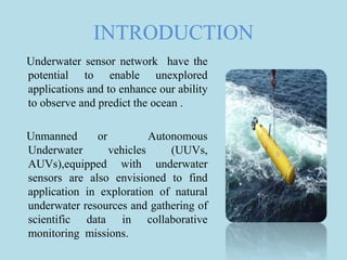
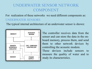
UNDERWATER SENSOR
NETWORK
BY
ADEEBA KHAN
MTECH CT
General Idea
Sensor
A Device that receives and respond to a signal
or stimulus.
As human we perceive the world via senses(
we can hear, taste, touch, see and smell).
Machine senses through sensors like
temperature sensors ,pressure sensors and
light sensors.
Sensor Network
Sensor networks are dense wireless networks of small, low-cost
sensors, which collect and disseminate environmental data.
Architecture of Sensor Network
Internet,
Satellite,
etc
Sink
Task
Manager
A
B
C
D
E
F
Sensor Node
Sensor Field
Key Technologies that enable sensor network:
 Micro electro-mechanical systems (MEMS)
 Wireless communications
 Digital electronics
Terrestrial sensor network
It typically consist of hundreds to thousands of inexpensive
wireless sensor nodes deployed in a given area ,either in ad
hoc or in a preplanned manner.
INTRODUCTION
Underwater sensor network have the
potential to enable unexplored
applications and to enhance our ability
to observe and predict the ocean .
Unmanned or Autonomous
Underwater vehicles (UUVs,
AUVs),equipped with underwater
sensors are also envisioned to find
application in exploration of natural
underwater resources and gathering of
scientific data in collaborative
monitoring missions.
APPLICATIONS
It enable abroad range of application:
 Ocean Sampling network
 Environmental monitoring
 Undersea Explorations
 Disaster prevention
 Seismic Monitoring
 Equipment monitoring
 Assisted Navigation
 Distributed Tactical Surveillance
 Mine Reconnaissance
CHALLENGES IN DESIGN OF
UNDERWATER NETWORK
 The available bandwidth is severely limited.
 The underwater channel is impaired because of multipath and
fading.
 Battery power is limited and usually batteries cannot be
recharged.
 Underwater sensors are prone to failures because of fouling
and corrosion.
DIFFERENCES WITH TERRESTRIAL
SENSOR NETWORKS
Underwater Sensor Network has to take care of living beings
that exist in Oceans and to protect their life while using
autonomous vehicles and sensors . Thus these network has to
be developed based on the challenges posed by the underwater
environment.
Beyond that underwater sensor network is different from
terrestrial sensor network in terms of :
 Cost
 Deployment
 Power
 Memory
 Spatial Correlation
UNDERWATER SENSOR NETWORK
COMPONENT
For realization of these networks we need different components as:
UNDERWATER SENSORS
The typical internal architecture of an underwater sensor is shown:
The controller receives data from the
sensor and can store the data in the on-
board memory, process them, and send
them to other network devices by
controlling the acoustic modem.
These devices include sensors to
measure the quality of water and to
study its characteristics.
• Examples of Underwater Sensors Node:
(a) (b)
• (a) Aquacomm underwater modem
• (b) LinkQuest underwater sensor nodes.
AUTONOMOUS UNDERWATER VEHICLES
Autonomous Underwater Vehicles (AUVs) are programmable,
robotic vehicles that, depending on their design, can drift, drive, or
glide through the ocean without real-time control by human
operators.
In addition to static sensor nodes, several types of AUVs exist as
experimental platforms for underwater experiments.
Examples of existing AUVs :
Odyssey-class AUVs developed at MIT (small scale submarines )
Odyssey AUV
Drifters and gliders are oceanographic instruments often used in
underwater exploration(simpler devices that do not encompass
such sophisticated capabilities).
View of a drifter from above (left) and
from below (right)
Spray glider.
COMMUNICATON ARCHITECTURE
The network topology is in general a crucial factor in determining
the energy consumption, the capacity, and the reliability of a
network.
The network capacity is also influenced by the network topology.
Since the capacity of the underwater channel is severely limited, a
it is very important to organize the network topology in such a
way that no communication bottleneck is introduced.
 Static 2-D UWSNs for ocean bottom monitoring
 Static 3-D UWSNs for ocean-column monitoring
 The 3-D networks of AUVs
Static 2-D UWSNs for ocean bottom monitoring:
• These are constituted by sensor nodes that are anchored to the
bottom of the ocean.
• Typical applications may be environmental monitoring, or
monitoring underwater plates in tectonics.
• Components used :
Architecture for 2-D
UWSNs.
Static 3-D UWSNs for ocean column monitoring
• These include networks of sensors whose depth can be
controlled by means of various techniques.
• May be used for surveillance applications or monitoring of
ocean phenomena (ocean bio/geo/chemical processes, water
streams, pollution).
• Components:
Architecture for 3-D UWSNs.
3-D Networks of AUVs
• These include networks of sensors whose depth can be
controlled by means of various techniques.
• May be used for surveillance applications or monitoring of
ocean phenomena (ocean bio/geo/chemical processes, water
streams, pollution).
AUV
The integration and enhancement of fixed sensor networks with
AUVs is an almost unexplored research area which requires new
network coordination algorithms such as:
• Adaptive sampling: This includes control strategies to command
the mobile vehicles to move to places where their data will be
most useful.
• Self-configuration: This includes control procedures to
automatically detect connectivity holes due to node failures or
channel impairment and request the intervention of an AUV.
Furthermore, AUVs can be used either for installation and
maintenance of the sensor network infrastructure or to deploy new
sensors.
Sensor network protocol stack
Physical Layer :Until the beginning of the last decade, due to the
challenging characteristics of the underwater channel, underwater
modem development was based on non-coherent frequency Shift
Keying (FSK) modulation, since it relies on energy detection and
thus does not require phase tracking, which is a very difficult task
mainly because of the Doppler-spread in the UW-A channel. In FSK
modulation schemes developed for underwater, the multi-path
effects are suppressed by inserting time guards between successive
pulses to ensure that the reverberation, caused by the rough ocean
surface and bottom, vanishes before each subsequent pulse is
received.
Data Link Layer :Channel access control in UW-ASNs poses
additional challenges because of the peculiarities of the underwater
channel, in particular limited bandwidth, and high and variable
delay.
Frequency Division Multiple Access (FDMA) is not suitable for
UW-ASNs due to the narrow bandwidth in UW-A channels and
the vulnerability of limited band systems to fading and multi-
path.
Time Division Multiple Access (TDMA) shows a limited
bandwidth efficiency because of the long time guards required
in the UW-A channel. In fact, long time guards must be designed
to account for the large propagation delay and delay variance of
the underwater channel.
Carrier Sense Multiple Access (CSMA) prevents collisions with the
ongoing transmission at the transmitter side. To prevent collisions at
the receiver side, however, it is necessary to add a guard time
between transmissions dimensioned according to the maximum
propagation delay in the network. This makes the protocol
dramatically inefficient for UW-ASNs.
Network Layer :The network layer is in charge of determining the
path between a source (the sensor that samples a physical
phenomenon) and a destination node (usually the surface station). In
general, while many impairments of the underwater acoustic
channel are adequately addressed at the physical and data link
layers, some other characteristics, such as the extremely long
propagation delays, are better addressed at the network layer.
The existing routing protocols are usually divided into three
categories, namely proactive, reactive and geographical routing
protocols.
Transport Layer :A transport layer protocol is needed in UW-ASNs
to achieve reliable transport of event features, and to perform flow
control and congestion control. Most existing TCP implementations
are unsuited for the underwater environment since the flow control
functionality is based on a window-based mechanism that relies on
an accurate estimate of the Round Trip Time (RTT). The long RTT,
which characterizes the underwater environment, would affect the
throughput of most TCP implementations. Furthermore, the
variability of the underwater RTT would make it hard to effectively
set the timeout of the window-based mechanism, which most
current TCP implementations rely on.
Application Layer :Channel access control in UW-ASNs poses
additional challenges because of the peculiarities of the underwater
channel, in particular limited bandwidth, and high and variable
delay.
The purpose of an application layer is multi-fold: i) provide a
network management protocol that makes hardware and software
details of the lower layers transparent to management applications;
ii) provide a language for querying the sensor network as a whole;
iii) assign tasks and advertise events and data.
SOURCES
 Underwater Acoustic Sensor Network
-edited by Yang Xiao
 http://nopr.niscair.res.in/bitstream/123456789/6203/1/IJMS
%2038%283%29%20267-273.pdf
 Wireless Sensor Networks
By Ian F. Akyildiz, Mehmet Can Vuran
 https://www.google.co.in/url?sa=t&rct=j&q=&esrc=s&source=web
&cd=6&cad=rja&uact=8&ved=0CDIQFjAF&url=http%3A%2F%2
Fwww.ece.rutgers.edu%2F~pompili%2Fpaper%2Fpompili_dario_2
00708_phd.pdf&ei=yPdAVbSLKcbauQT1mYHoDg&usg=AFQjCN
FTfU1ebFGjgxlnhN0PgeAsOb06Xw&sig2=_-
zC3vVa5TZW98TyGFxRmA&bvm=bv.92189499,d.c2E
Underwater sensor network

Underwater sensor network

  • 1.
  • 2.
    General Idea Sensor A Devicethat receives and respond to a signal or stimulus. As human we perceive the world via senses( we can hear, taste, touch, see and smell). Machine senses through sensors like temperature sensors ,pressure sensors and light sensors.
  • 3.
    Sensor Network Sensor networksare dense wireless networks of small, low-cost sensors, which collect and disseminate environmental data. Architecture of Sensor Network Internet, Satellite, etc Sink Task Manager A B C D E F Sensor Node Sensor Field
  • 4.
    Key Technologies thatenable sensor network:  Micro electro-mechanical systems (MEMS)  Wireless communications  Digital electronics Terrestrial sensor network It typically consist of hundreds to thousands of inexpensive wireless sensor nodes deployed in a given area ,either in ad hoc or in a preplanned manner.
  • 5.
    INTRODUCTION Underwater sensor networkhave the potential to enable unexplored applications and to enhance our ability to observe and predict the ocean . Unmanned or Autonomous Underwater vehicles (UUVs, AUVs),equipped with underwater sensors are also envisioned to find application in exploration of natural underwater resources and gathering of scientific data in collaborative monitoring missions.
  • 6.
    INTRODUCTION Underwater sensor networkhave the potential to enable unexplored applications and to enhance our ability to observe and predict the ocean . Unmanned or Autonomous Underwater vehicles (UUVs, AUVs),equipped with underwater sensors are also envisioned to find application in exploration of natural underwater resources and gathering of scientific data in collaborative monitoring missions.
  • 7.
    APPLICATIONS It enable abroadrange of application:  Ocean Sampling network  Environmental monitoring  Undersea Explorations  Disaster prevention  Seismic Monitoring  Equipment monitoring  Assisted Navigation  Distributed Tactical Surveillance  Mine Reconnaissance
  • 8.
    CHALLENGES IN DESIGNOF UNDERWATER NETWORK  The available bandwidth is severely limited.  The underwater channel is impaired because of multipath and fading.  Battery power is limited and usually batteries cannot be recharged.  Underwater sensors are prone to failures because of fouling and corrosion.
  • 9.
    DIFFERENCES WITH TERRESTRIAL SENSORNETWORKS Underwater Sensor Network has to take care of living beings that exist in Oceans and to protect their life while using autonomous vehicles and sensors . Thus these network has to be developed based on the challenges posed by the underwater environment. Beyond that underwater sensor network is different from terrestrial sensor network in terms of :  Cost  Deployment  Power  Memory  Spatial Correlation
  • 10.
    UNDERWATER SENSOR NETWORK COMPONENT Forrealization of these networks we need different components as: UNDERWATER SENSORS The typical internal architecture of an underwater sensor is shown: The controller receives data from the sensor and can store the data in the on- board memory, process them, and send them to other network devices by controlling the acoustic modem. These devices include sensors to measure the quality of water and to study its characteristics.
  • 11.
    • Examples ofUnderwater Sensors Node: (a) (b) • (a) Aquacomm underwater modem • (b) LinkQuest underwater sensor nodes.
  • 12.
    AUTONOMOUS UNDERWATER VEHICLES AutonomousUnderwater Vehicles (AUVs) are programmable, robotic vehicles that, depending on their design, can drift, drive, or glide through the ocean without real-time control by human operators. In addition to static sensor nodes, several types of AUVs exist as experimental platforms for underwater experiments. Examples of existing AUVs : Odyssey-class AUVs developed at MIT (small scale submarines ) Odyssey AUV
  • 13.
    Drifters and glidersare oceanographic instruments often used in underwater exploration(simpler devices that do not encompass such sophisticated capabilities). View of a drifter from above (left) and from below (right) Spray glider.
  • 14.
    COMMUNICATON ARCHITECTURE The networktopology is in general a crucial factor in determining the energy consumption, the capacity, and the reliability of a network. The network capacity is also influenced by the network topology. Since the capacity of the underwater channel is severely limited, a it is very important to organize the network topology in such a way that no communication bottleneck is introduced.  Static 2-D UWSNs for ocean bottom monitoring  Static 3-D UWSNs for ocean-column monitoring  The 3-D networks of AUVs
  • 15.
    Static 2-D UWSNsfor ocean bottom monitoring: • These are constituted by sensor nodes that are anchored to the bottom of the ocean. • Typical applications may be environmental monitoring, or monitoring underwater plates in tectonics. • Components used :
  • 16.
  • 17.
    Static 3-D UWSNsfor ocean column monitoring • These include networks of sensors whose depth can be controlled by means of various techniques. • May be used for surveillance applications or monitoring of ocean phenomena (ocean bio/geo/chemical processes, water streams, pollution). • Components:
  • 18.
  • 19.
    3-D Networks ofAUVs • These include networks of sensors whose depth can be controlled by means of various techniques. • May be used for surveillance applications or monitoring of ocean phenomena (ocean bio/geo/chemical processes, water streams, pollution). AUV
  • 20.
    The integration andenhancement of fixed sensor networks with AUVs is an almost unexplored research area which requires new network coordination algorithms such as: • Adaptive sampling: This includes control strategies to command the mobile vehicles to move to places where their data will be most useful. • Self-configuration: This includes control procedures to automatically detect connectivity holes due to node failures or channel impairment and request the intervention of an AUV. Furthermore, AUVs can be used either for installation and maintenance of the sensor network infrastructure or to deploy new sensors.
  • 21.
    Sensor network protocolstack Physical Layer :Until the beginning of the last decade, due to the challenging characteristics of the underwater channel, underwater modem development was based on non-coherent frequency Shift Keying (FSK) modulation, since it relies on energy detection and thus does not require phase tracking, which is a very difficult task mainly because of the Doppler-spread in the UW-A channel. In FSK modulation schemes developed for underwater, the multi-path effects are suppressed by inserting time guards between successive pulses to ensure that the reverberation, caused by the rough ocean surface and bottom, vanishes before each subsequent pulse is received.
  • 22.
    Data Link Layer:Channel access control in UW-ASNs poses additional challenges because of the peculiarities of the underwater channel, in particular limited bandwidth, and high and variable delay. Frequency Division Multiple Access (FDMA) is not suitable for UW-ASNs due to the narrow bandwidth in UW-A channels and the vulnerability of limited band systems to fading and multi- path. Time Division Multiple Access (TDMA) shows a limited bandwidth efficiency because of the long time guards required in the UW-A channel. In fact, long time guards must be designed to account for the large propagation delay and delay variance of the underwater channel.
  • 23.
    Carrier Sense MultipleAccess (CSMA) prevents collisions with the ongoing transmission at the transmitter side. To prevent collisions at the receiver side, however, it is necessary to add a guard time between transmissions dimensioned according to the maximum propagation delay in the network. This makes the protocol dramatically inefficient for UW-ASNs.
  • 24.
    Network Layer :Thenetwork layer is in charge of determining the path between a source (the sensor that samples a physical phenomenon) and a destination node (usually the surface station). In general, while many impairments of the underwater acoustic channel are adequately addressed at the physical and data link layers, some other characteristics, such as the extremely long propagation delays, are better addressed at the network layer. The existing routing protocols are usually divided into three categories, namely proactive, reactive and geographical routing protocols.
  • 25.
    Transport Layer :Atransport layer protocol is needed in UW-ASNs to achieve reliable transport of event features, and to perform flow control and congestion control. Most existing TCP implementations are unsuited for the underwater environment since the flow control functionality is based on a window-based mechanism that relies on an accurate estimate of the Round Trip Time (RTT). The long RTT, which characterizes the underwater environment, would affect the throughput of most TCP implementations. Furthermore, the variability of the underwater RTT would make it hard to effectively set the timeout of the window-based mechanism, which most current TCP implementations rely on.
  • 26.
    Application Layer :Channelaccess control in UW-ASNs poses additional challenges because of the peculiarities of the underwater channel, in particular limited bandwidth, and high and variable delay. The purpose of an application layer is multi-fold: i) provide a network management protocol that makes hardware and software details of the lower layers transparent to management applications; ii) provide a language for querying the sensor network as a whole; iii) assign tasks and advertise events and data.
  • 27.
    SOURCES  Underwater AcousticSensor Network -edited by Yang Xiao  http://nopr.niscair.res.in/bitstream/123456789/6203/1/IJMS %2038%283%29%20267-273.pdf  Wireless Sensor Networks By Ian F. Akyildiz, Mehmet Can Vuran  https://www.google.co.in/url?sa=t&rct=j&q=&esrc=s&source=web &cd=6&cad=rja&uact=8&ved=0CDIQFjAF&url=http%3A%2F%2 Fwww.ece.rutgers.edu%2F~pompili%2Fpaper%2Fpompili_dario_2 00708_phd.pdf&ei=yPdAVbSLKcbauQT1mYHoDg&usg=AFQjCN FTfU1ebFGjgxlnhN0PgeAsOb06Xw&sig2=_- zC3vVa5TZW98TyGFxRmA&bvm=bv.92189499,d.c2E

Editor's Notes

  • #21 The integration and enhancement of fixed sensor networks with AUVs is an almost unexplored research area which requires new network coordination algorithms such as: • Adaptive sampling: This includes control strategies to command the mobile vehicles to move to places where their data will be most useful. This approach is also known as adaptive sampling and has been used in monitoring missions such as in [5]. For example, the density of sensor nodes can be adaptively increased in a given area when a higher sampling rate is needed for a given monitored phenomenon. • Self-configuration: This includes control procedures to automatically detect connectivity holes due to node failures or channel impairment and request the intervention of an AUV. Furthermore, AUVs can be used either for installation and maintenance of the sensor network infrastructure or to deploy new sensors. They can also be used as temporary relay nodes to restore connectivity. One of the design objectives of AUVs is to make them rely on local intelligence and less dependent on communications from onshore