Download to read offline


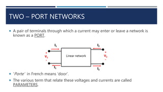

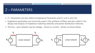
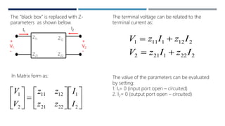
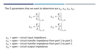
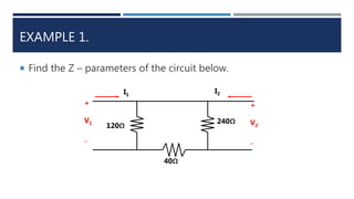
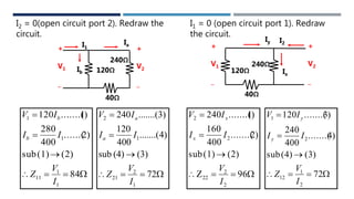
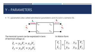
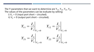
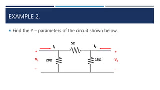
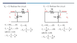

This document discusses two-port networks and their parameters. It defines a two-port network as having two ports through which current can enter or leave. The document introduces Z-parameters and Y-parameters as ways to relate the voltages and currents in a linear two-port network. Z-parameters express the terminal current in terms of voltage, while Y-parameters express the terminal voltage in terms of current. The document provides examples of calculating the Z-parameters and Y-parameters of simple resistor networks by opening or shorting the ports.