
Download to read offline

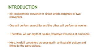
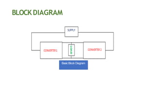
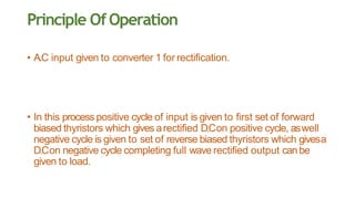
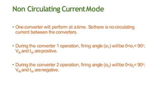
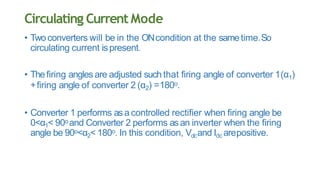
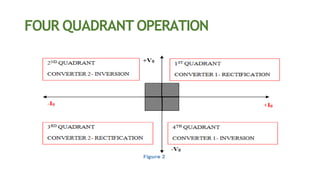
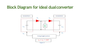

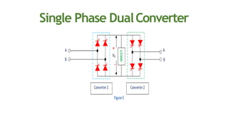
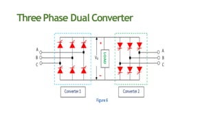

This document discusses dual converters, which comprise two converters - one that performs rectification and the other performs inversion. It begins with an introduction and provides a block diagram. It then explains the principles of operation in both non-circulating and circulating current modes. Four quadrant operation is also discussed. Ideal dual converters have ripple-free output voltage. The document concludes by covering types of dual converters (single and three-phase) and their applications such as controlling DC motor direction and speed.


