
Download to read offline

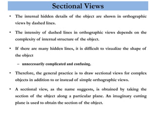
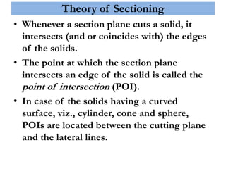
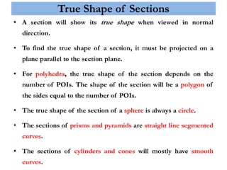
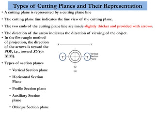
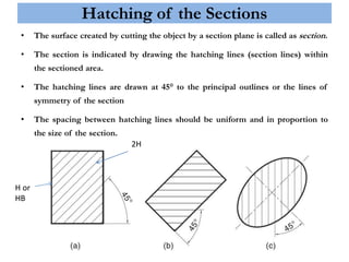
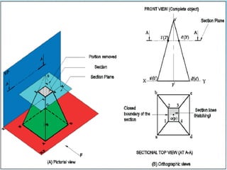
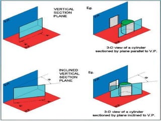
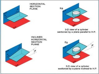
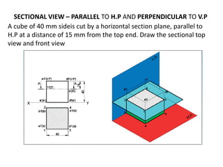
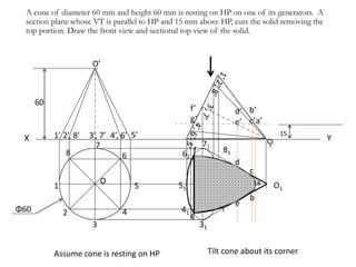
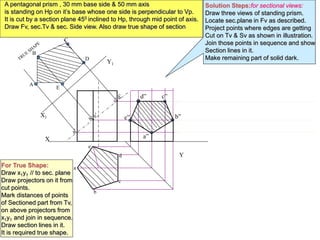
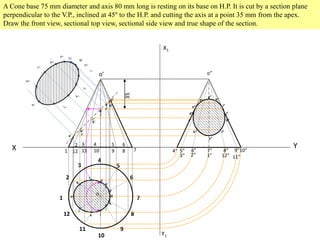
The document discusses sectional orthographic projection and includes: - Sectional views show internal details of an object using dashed hidden lines, with complexity depending on the object's internal structure. Complex objects use sectional views instead of orthographic views. - A sectional view is obtained by an imaginary cutting plane that intersects edges of a solid. Points of intersection define the section's shape as a polygon with sides equal to points of intersection. - Cutting planes are shown as lines with arrowheads indicating the viewing direction. Common planes include vertical, horizontal, profile, auxiliary and oblique. Hatching indicates the cut surface. - Examples provide step-by-step solutions for drawing sectional


![Sectionanddevelopment(thedirectdata[1].com)](https://cdn.slidesharecdn.com/ss_thumbnails/sectionanddevelopmentthedirectdata1-170802182625-thumbnail.jpg?width=640&height=640&fit=bounds)


