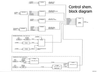
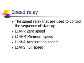
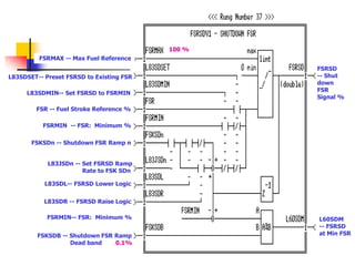
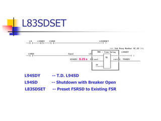
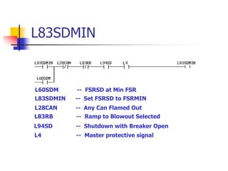
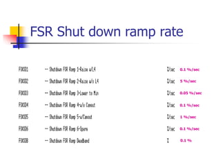
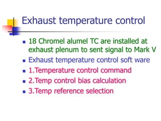
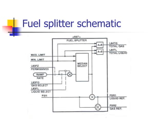
The document describes the control system of a gas turbine. It discusses the various control loops for startup control, speed control, temperature control and shutdown control. It explains how fuel control is done through fuel stroke reference signals and describes the liquid and gas fuel control systems. It also discusses temperature reference selection, inlet guide vane modulation and dual fuel control functionality.


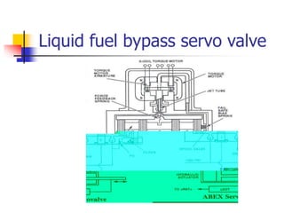
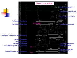
![Liquid Fuel Stop Valve
Control Signal
Flow divider mag
pickup speed
Liq fuel bypass valve
servo current
Liquid Fuel Stroke Ref
from Fuel Splitter %
Turbine Speed %
Master protective signal
Calibration position reference %
Calib selection command pass code
Excessive Liq Fuel Startup
8.5 %
Liq Fuel Bypass Valve Flow Detection
Trouble Set point 3 %
LF. Byp. Vlv. Servo Current
Trouble Alarm
30 %
10 sec
Master reset
Liq Fuel Bypass Valve Flow
Detected Trouble Alarm
Liquid Fuel Flow High (trip )
Liq Fuel Flow Reference Angle %
Liquid fuel bypass valve
servo command[65FP-1]
ALM171:'LIQUID FUEL CONTROL FAULT'](https://image.slidesharecdn.com/36809944-gas-turbine-control-221230021547-bda79422/85/36809944-Gas-Turbine-Control-ppt-52-320.jpg)
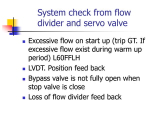
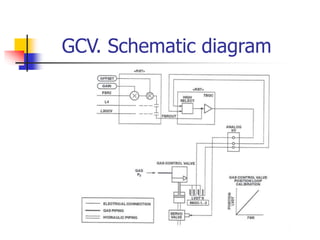
![Gas control valve out put
Gas Fuel Stroke Ref
from Fuel Splitter
GCV servo command
[65GC-1] %
Calibration position reference %
Calibration selection command pass code
Gas Fuel Stop Valve Open
Master protective signal](https://image.slidesharecdn.com/36809944-gas-turbine-control-221230021547-bda79422/85/36809944-Gas-Turbine-Control-ppt-57-320.jpg)
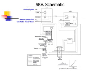
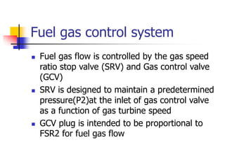
![SRV. Out put signal
Fuel Gas Press Ratio
Control Gain 3.5146 psi/%
Fuel Gas Press Ratio Control Offset
-17.88 psi
Stop/Speed Ratio Valve
Shutdown Command Set point
-40 psi
Gas Ratio Valve Control Press Ref psi
Stop/speed ratio valve servo
command [90SR-1] psi
Gas Ratio Valve Control Press Ref (psi)](https://image.slidesharecdn.com/36809944-gas-turbine-control-221230021547-bda79422/85/36809944-Gas-Turbine-Control-ppt-59-320.jpg)
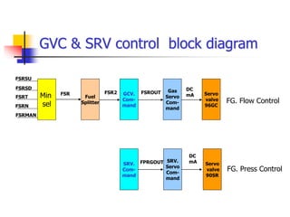
![Gas control valve
servo current %
Position fdbck gas
controlvalve [96GC-1] %
Gas Fuel Stroke Ref
from Fuel Splitter %
Position fdbck gas
controlvalve [96GC-1] % 3 %
3 sec
5 %
5 sec
Gas control valve not
following reference
Gas control valve not
following reference trip
Gas Control Valve
Position Feedback Fault
Gas Control Valve
Open Trouble Alarm
Gas Control Valve
Servo Current Fault
ALM133:'GAS CONTROL
VALVE SERVO TROUBLE'
-5 %
5 %
37.5 %
Gas Fuel Stop Valve Open
3 sec
COMMAND PB Master reset](https://image.slidesharecdn.com/36809944-gas-turbine-control-221230021547-bda79422/85/36809944-Gas-Turbine-Control-ppt-61-320.jpg)
![Speed ratio valve
servo current %
Interstage fuel gas press
xmitter [96FG-2A] psi
Position fdbck srv
[96SR-1] %
ALM134:'GAS FUEL INTERVALVE
PRESSURE TROUBLE'
Gas Ratio Valve Open
Stop/Ratio Valve Position
FeedbackTrouble Alarm Lo
ALM132:'GAS RATIO VALVE
POSITION SERVO TROUBLE'
Stop/Ratio Valve
Open Trouble Alarm
Stop/Ratio Valve Servo
Current Trouble Alarm
Startup Gas Fuel Stroke High
COMMAND PB Master reset
-5 psi
2 sec
-6.67 %
6.67 %
15 %
33.3 %](https://image.slidesharecdn.com/36809944-gas-turbine-control-221230021547-bda79422/85/36809944-Gas-Turbine-Control-ppt-62-320.jpg)
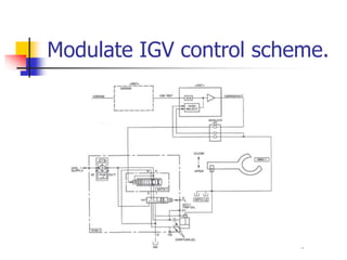
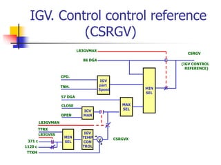
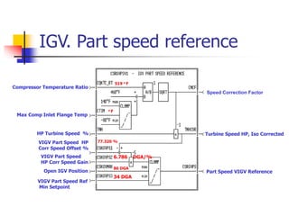
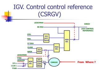
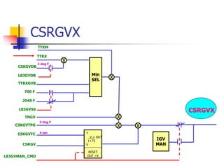
![VIGV Temp Control Airflow Ref Offset
Turb inlet guide vane servo
vlv command [90TV-1] DGA
IGV. Control Algorithm from Mark V
IGV Part speed control
86 DGA
CPRS. OFF Line washing
VIGV. Reference Angle (DGA)
57 DGA
57 DGA
Permissive Inlet Guide Vane Ref
IGV Manual Control Permissive
0 DGA
Stator 17 IGV Gain
1 DGA/%
Airflow Control Reference % IGV on Temperature Control
IGV at Minimum Position
IGV at Maximum Position
Temp Control and
Manual Control Ref
Calibration selection
command pass code
Calibration position reference %](https://image.slidesharecdn.com/36809944-gas-turbine-control-221230021547-bda79422/85/36809944-Gas-Turbine-Control-ppt-73-320.jpg)
![IGV. Fault detection
Position feedback
IGV [96TV-1]
31 DGA
35 DGA
-30 %
IGV Control Permissive
5 sec
COMMAND PB Master reset
IGV - Loss of Feedback Alarm
IGV - Vanes Open Alarm
IGV - Servo Current Alarm
- Neg. Saturation
TCQA-REG-CUR IGV
control servo current
DGA
%](https://image.slidesharecdn.com/36809944-gas-turbine-control-221230021547-bda79422/85/36809944-Gas-Turbine-Control-ppt-80-320.jpg)
![IGV. Not following CSRGV.
Position feedback IGV
[96TV-1] DGA
VIGV Reference Angle DGA
ALM108:'INLET GUIDE VANE
CONTROL TROUBLE ALARM'
IGV Not Following CSRGV Trip
7.5 DGA
5 SEC
7.5 DGA
5 SEC](https://image.slidesharecdn.com/36809944-gas-turbine-control-221230021547-bda79422/85/36809944-Gas-Turbine-Control-ppt-81-320.jpg)