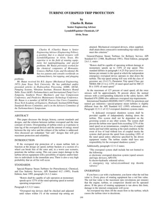
Charles R. Rutan is a senior engineering advisor for Lyondell/Equistar Chemicals in Alvin, Texas. He has expertise in rotating equipment, hot tapping, and special engineering problems. This document discusses turbine overspeed trip protection. It describes the standards and designs for overspeed protection systems on steam turbines. It addresses the potential issues if an overspeed trip fails, like equipment damage or injury. It also discusses the factors that determine how fast a turbine can overspeed after a load loss, such as the rotor's time constant and any stored energy between the turbine and steam supply. Redundant and fast-acting overspeed systems are needed to safely shut down the turbine in the event of a load loss.
The document discusses the basics of steam turbines. It explains that steam turbines convert the potential energy of high-pressure, high-temperature steam into kinetic energy and then mechanical energy. This mechanical energy can be used to drive rotating equipment. Steam turbines are preferred in process plants because waste heat from reactions generates high-pressure steam. The document describes the main types of turbines and compares impulse and reaction turbines. It also outlines key components, safety devices, starting procedures, maintenance checks, and losses within steam turbine systems.
The document discusses steam turbine losses and how to identify them. It outlines several types of losses including mechanical damages, flow area decreases or increases, and flow area bypasses. Specific examples of each type of loss are provided along with their symptoms and causes. These losses can lead to reduced turbine efficiency. The document also discusses the impact of deviations from design parameters on heat rate and gives an example analysis of efficiency losses for a KWU turbine.
This document discusses common issues that arise during the commissioning stage of oil and gas projects. It begins by explaining that commissioning involves testing systems using substitute fluids and inhibited control functions, presenting new challenges compared to normal operation. Eight specific issues that often cause problems are then described in detail, including compressor damage from an unmonitored suction strainer, mechanical seal failures from contamination, high pump vibrations from improper installation, and safety hazards from a lack of safe design. The document emphasizes that addressing potential issues early in engineering and design can help avoid problems during commissioning.
The gas turbine is an internal combustion engine that uses air as the working fluid. The engine extracts chemical energy from fuel and converts it to mechanical energy using the gaseous energy of the working fluid (air) to drive the engine and propeller, which, in turn, propel the aeroplane.
This deals with Boiler feed pumps used in power plants .
contains details about the KHI and FK series pumps , technical parameters and maintenance prctices followed for these pumps
The document discusses condition monitoring for steam turbines. It outlines several key points:
1. Condition monitoring methods for steam turbines include monitoring steam conditions and flow rates, vibration, lubrication conditions, bearing condition, rotor speed, noise levels, and auxiliary system operation.
2. Common failure modes of steam turbines include bearing failures from loss of lubrication or contamination, blade failures from foreign object damage or fatigue, and valve failures from solid particle damage or erosion.
3. Condition monitoring is important for identifying faults early to allow corrective action to save assets and avoid production losses. Monitoring methods help ascertain equipment condition while failure modes can be prevented through monitoring and preventive maintenance.
This document provides information about steam generators and coal-fired power plants. It discusses the basics of how coal is converted to electricity in several steps: coal is burned to create heat energy, which turns water into high-pressure steam, which spins turbines connected to generators to create electrical energy. It also describes the major components involved like boilers, turbines, condensers, and alternators. Furthermore, it compares the technical specifications and costs of 660MW and 500MW subcritical and supercritical steam generators.
Steam turbines work by converting the energy of expanding steam into rotational motion. They have several key components and come in two main types: impulse and reaction. Impulse turbines use nozzles to direct high velocity steam onto turbine blades for impulse, while reaction turbines utilize both fixed and moving blades to expand steam. Common problems in steam turbines include stress corrosion cracking, corrosion fatigue, thermal fatigue, and pitting due to chemical attack from corrosive elements in the steam. Proper lubrication and preventing blade deterioration are important for optimizing steam turbine performance and lifespan.
In this presentation study on the basic parts of the steam turbine as following turbine casting, turbine rotors, turbine blades, shrouds, turbine bearing device, turbine seals, turbine couplings, governor and lubrication system.
This document discusses the Rankine cycle, which is a thermodynamic cycle derived from the Carnot vapor power cycle. It consists of four processes: 1) Isobaric heat supply in the boiler where water is heated to high pressure steam, 2) Adiabatic expansion of the steam in a turbine to produce work, 3) Isobaric heat rejection in the condenser where the steam is condensed back to water, and 4) Adiabatic pumping of the condensate back to the boiler to complete the cycle. The heat and work transfers are also defined for each process.
Pre commissioning steam turbines load trialNagesh H
The document discusses pre-commissioning and commissioning activities for a steam turbine. Pre-commissioning includes steam blowing of lines, condenser testing like leak and vacuum drop tests, checking bearing clearances and dumps, setting throttle valves, and verifying safety trips. Commissioning procedures cover starting the turbine in solo run and load run modes while monitoring vibration levels and other parameters. Load trial data is collected and actual steam consumption is compared to projected values, with correction factors applied. Problems faced on site included low dump values due to nozzle chest welding issues and high CEP current due to pump-motor misalignment.
The document discusses vibration theory, including definitions of acceleration, velocity, displacement and simple harmonic motion. It describes quantifying vibration amplitude using peak-to-peak, peak, average and RMS levels. It also covers the differences between time and frequency domain analysis and concepts of phase angle measurement in condition monitoring. Condition monitoring strategies aim to focus on critical machinery by defining detectable faults and relevant measurement parameters.
1. This document provides maintenance guidelines for reciprocating ammonia feed pumps, including maintenance for tandem valves, plunger packing, and crank cases.
2. Tandem valve maintenance should be performed every 4 months and includes cleaning, lubricating, and replacing O-rings.
3. Plunger packing should be checked regularly and replaced every 2-2.5 years depending on quality. Packing outlet ammonia content should be monitored and packing tightened if over 12%.
4. Crank case maintenance includes checking for water, oil leaks, excessive heat, and measuring clearance of the overload protection switch.
This document provides formulas and explanations for key parameters in centrifugal pump performance including head, flow rate, power, efficiency, specific speed, suction specific speed, and affinity laws. These formulas and concepts are used to evaluate pump performance, troubleshoot issues, estimate operating points, protect from cavitation, select suitable seals, and implement control systems. Symbols are defined for pressure, power, flow rate, speed, voltage, current, and efficiency.
This document discusses the key aspects of a 134 MW steam turbine. It begins by defining a steam turbine as a device that extracts thermal energy from pressurized steam and converts it into mechanical energy. It then provides specific design data for a 134 MW turbine, including its rated output, speed, steam conditions, number of extractions and stages. The document goes on to classify turbines based on their steam flow, type of energy conversion, compounding, cylinder arrangement, and exhaust conditions. It describes impulse, reaction, and combined impulse-reaction turbines as well as tandem and cross-compound cylinder arrangements.
In modern power plants, extensive protections and interlocks are provided to isolate faulty equipment without causing further damage and allow reserve equipment to start up automatically. Protections detect abnormal parameters and trip equipment to prevent major damage. Interlocks make equipment states dependent to prevent incorrect operation. Protections include tripping the turbine for issues like high/low steam pressure, temperature, exhaust hood temperature, axial shift, differential expansion, eccentricity, pump failures, and low lubricating oil pressure.
The document discusses steam turbines, including their basic components and operating principles. It describes the main types of steam turbines such as condensing, extraction, and reheat turbines. It also discusses the key parts like nozzles, blades, bearings, seals, monitoring systems, and control valves. The final section provides an overview of the typical start-up procedure for a steam turbine, including lubrication, turning, control system checks, and testing of valves before admitting steam.
Steam turbine over speed trip systems (6)Prem Baboo
This document discusses steam turbine overspeed trip systems. It describes how the tripping device works by draining governing oil pressure when the turbine needs to be tripped, causing the stop valve piston disc and control valves to close. It also discusses the overspeed governor, which protects the turbine from speeds higher than safe operating value. The overspeed governor uses an eccentric pin within the turbine shaft that moves outward at a preset trip speed due to centrifugal force, actuating the tripping device. Finally, it describes an eccentric pin mechanical overspeed system that is separate from the governing systems and uses an unbalanced pin to trigger a trip at a preset overspeed threshold.
This document discusses the design and operation of a lube oil rundown tank system used to provide lubrication to rotating equipment bearings during shutdown coast-down periods. It describes how the rundown tank is filled during startup and then provides gravity flow of lube oil to the bearings after shutdown when main and auxiliary lube oil pumps are lost. The rundown tank system includes components like a vent, level transmitter, filling valve, check valves, and overflow line that allow it to fill, circulate oil normally, and then feed oil to bearings during coast-down.
Boiler purge is the basic process of resetting boiler before lightup. This presentation explains the logic, schematics & working of purge procedure. For enhanced knowledge of this topic, I can be reached at tahoorkhn03@gmail.com.
Combustion and dry low nox 2.6 dln systemFaisal Nadeem
I have explained the combustion and DLN2.6, dry low nox 2.6 + with better understanding. Trainings from Experts and my personal experience on gas turbines helps me understand the DLN 2.6 system. I hope trainee from Power Plants will like the slide. its good work of research for young trainees at Power Plants
The document provides information on governing systems and common problems encountered. It discusses:
1. The key components of a governing system block diagram including pumps, valves, filters and overspeed testers.
2. Cleaning procedures and stroke check requirements for governing systems.
3. Parameters that should be followed including pressures, signals, valve lifts and temperatures.
4. Common governing problems like hunting, chattering, and sudden speed variations.
5. Case studies examining issues like improper servomotor assembly and a bent pilot valve spring causing load hunting.
The document discusses turbine governing systems. The objective of turbine governing is to control the steam flow to a turbine to maintain a constant rotation speed as load varies. It describes three common types of governing: throttle, nozzle, and bypass. The key components of a hydro-mechanical governing system are then outlined, including the speed governor, pilot valves, control valves, and emergency shutdown mechanisms. Protection systems using hydraulic and electrical trips are also summarized to safely operate the turbine.
Turbine Stress Control Logic, Calculation & WorkingTahoor Alam Khan
Turbine Stress Control is one of the complex logics of BHEL turbine. This presentation clearly explains the Logic, working, calculations and influence of the same on operation of steam turbine. For further details and understanding, I can be reached on tahoorkhn03@gmail.com.
The document discusses the major components of steam turbines, including the casing, nozzles, blades, rotor, bearings, governors, and safety devices. It describes the functions of key parts like the nozzle, blades, governors, and oil pumps. It also classifies steam turbines based on the method of steam expansion, flow direction, final pressure, number of stages, and pressure. The document provides information on standards, parameter ranges, troubleshooting, and starting procedures for steam turbines.
The document describes the components and operation of an emergency hydraulic (EH) oil system used for turbine protection. It includes descriptions of valves that operate to close the steam valves during a trip, accumulator tanks that maintain oil pressure, and filters and coolers that clean and regulate the oil temperature. The system uses oil pressure to activate actuators that rapidly close steam valves if protective devices detect a problem condition like overspeed or low pressure.
1) A compressor takes in air at atmospheric pressure and compresses it, delivering it at a higher pressure to a storage vessel.
2) Reciprocating compressors use pistons driven by a crankshaft to compress air in cylinders. As the piston moves, the air is compressed and discharged from the cylinder.
3) The work required to compress air depends on the pressure and volume changes. Actual work done is greater than theoretical isothermal work due to heat transfer during compression.
The document provides an overview of a turbine governing system. It discusses the key components and functions of hydraulic and electro-hydraulic governing systems used for a 200MW KWU turbine. These include speed and load controllers, governing system devices like the starting device and speeder gear, protective devices like overspeed trips, and the working of the hydraulic and electro-hydraulic systems. Different oils used and the selection process between the hydraulic and electro-hydraulic governors are also summarized.
Fault Detection and Failure Prediction Using Vibration AnalysisTristan Plante
This document discusses using vibration analysis to detect faults and predict failures in rotating equipment like electric motors. It describes an experiment where vibration data was collected from a motor under normal operation and different fault conditions (unbalance, mechanical looseness, bearing defect). The data was analyzed using spectrum analysis software and MATLAB. Specific fault frequencies were identified that corresponded to the type of fault. The results support using vibration analysis to monitor equipment condition and enable predictive maintenance by detecting issues before catastrophic failures occur.
Condition monitoring of induction motor with a case studyIAEME Publication
This document summarizes a study on condition monitoring of an induction motor. The study utilized multiple monitoring techniques including temperature monitoring, vibration analysis, motor current signature analysis, and shaft voltage measurement. Temperature, vibration, and shaft voltage readings were found to be within normal limits, indicating the motor was in good health. Motor current signature analysis detected no issues, further confirming the healthy state of the motor. The study demonstrated how a combination of condition monitoring techniques can evaluate the overall condition and help plan preventive maintenance for motors.
Condition monitoring of induction motor with a case studyIAEME Publication
This document summarizes a study on condition monitoring of an induction motor. It discusses various monitoring methods like temperature monitoring, vibration analysis, motor current signature analysis, and shaft voltage measurement. Temperature monitoring identified hotspots indicating potential insulation or cooling issues. Vibration analysis found peaks corresponding to unbalance, misalignment, and bearing or looseness issues. Motor current signature analysis identified rotor bar and joint issues by analyzing current waveforms. Together these methods provided a comprehensive assessment of the motor's health to guide maintenance.
Experimental Validation of Vibration Characteristics of Selected Centrifugal ...IRJET Journal
This document presents an experimental study on the vibration characteristics of a selected centrifugal pump. It begins with an introduction to pump vibrations and their causes. Next, it describes the methodology which includes measuring existing vibration levels, developing methods to reduce vibration, and experimenting with different isolation methods. Experimental results show that a grooved circular isolator is most effective at reducing vibration amplitudes while also increasing the first fundamental frequency to avoid resonance conditions. The conclusions determine that a grooved isolator is recommended for use with centrifugal pumps to minimize vibrations.
This document provides specifications for several models of Rexroth Hydraulic variable displacement axial piston pumps. The pumps are designed to provide efficient hydraulic power by varying their displacement based on system demand. Key details include pump dimensions, flow rates, pressure ratings, port locations, and recommended hose sizes for different models. Safety cautions are also provided regarding the operation and servicing of hydraulic systems.
Thrust Vector Control and Flight Control Systems for the Space Shuttle OrbiterMatt Bartholomew
A paper concerning the Thrust Vector Control (TVC) and Flight Control Systems (FCS) on the Space Shuttle Orbiter. This paper is primarily concerned with the hydraulics power systems features of these systems and presents some simple calculations.
IRJET- Development of Modern Electrical Steering Gear System on Board Shi...IRJET Journal
This document discusses the development of modern electrical steering gear systems on ships that incorporate autopilot functionality. It begins with an overview of existing ship steering systems and their various operating modes, including autopilot, follow-up, non-follow-up, and emergency modes. It then presents the development of a new permanent magnet linear synchronous actuator (PMLSA) system as an alternative to traditional electro-hydraulic systems. The PMLSA is designed to provide high torque at low speeds for steering applications while offering benefits like reduced weight, size, maintenance needs, and improved efficiency compared to hydraulic systems. The document also discusses incorporating a magnetic compass feed unit as a backup navigation input for the autopilot in case of gyro compass failure.
IRJET- Individual Wheel Control and Hand Brake SystemIRJET Journal
This document describes an individual wheel control and hand brake system for vehicles. It begins with an abstract that outlines an innovative idea to replace the traditional brake lever with a switch-type hand braking system. This would help overcome issues like lever jamming. It then provides details on how the system works, which includes a brake pedal, master cylinder, brake drum, control switch, and brake lines. The control switch can control the pressure of brake oil passing through it to individually apply brakes to wheels. Advantages over traditional hand brakes include more effective braking ability and ability to brake individual wheels, such as if one is stuck in mud. The document also provides background information on hydraulic braking systems, master cylinders, and
CASE 580SN TRACTOR LOADER BACKHOE Service Repair Manualhsemmd uksjemd
This is the Highly Detailed factory service repair manual for theCASE 580SN TRACTOR LOADER BACKHOE, this Service Manual has detailed illustrations as well as step by step instructions,It is 100 percents complete and intact. they are specifically written for the do-it-yourself-er as well as the experienced mechanic.CASE 580SN TRACTOR LOADER BACKHOE Service Repair Workshop Manual provides step-by-step instructions based on the complete dis-assembly of the machine. It is this level of detail, along with hundreds of photos and illustrations, that guide the reader through each service and repair procedure. Complete download comes in pdf format which can work under all PC based windows operating system and Mac also, All pages are printable. Using this repair manual is an inexpensive way to keep your vehicle working properly.
Service Repair Manual Covers:
Introduction
Hydraulic, pneumatic, electrical, electronic systems
Primary hydraulic power system
Secondary hydraulic power system
Electrical power system
Fault codes
Engine and pto in
Engine
Fuel and injection system
Exhaust system
Engine coolant system
Starting system
Transmission, drive and pto out
Transmission power shuttle
Transmission powershift
Axles, brakes and steering
Front axle
Rear axle
Steering hydraulic
Service brake hydraulic
Parking brake mechanical
Wheels and tracks wheels
Frame and cab
Frame primary frame
Shield
User controls and seat
User controls and seat operator seat
User platform
Environment control air-conditioning system
Frame positioning
Stabilising working stabilising
Tool positioning
Lifting
Hitch and working tool
Boom lift
Boom swing
Dipper lift
Dipper extension
Arm tool attachment tilt
Excavating and landscaping
Digging non-articulated digging tools
Carrying articulated tools
Electrical schematics
Hydraulic schematics
File Format: PDF
Compatible: All Versions of Windows & Mac
Language: English
Requirements: Adobe PDF Reader
NO waiting, Buy from responsible seller and get INSTANT DOWNLOAD, Without wasting your hard-owned money on uncertainty or surprise! All pages are is great to haveCASE 580SN TRACTOR LOADER BACKHOE Service Repair Workshop Manual.
Looking for some other Service Repair Manual,please check:
https://www.aservicemanualpdf.com/
Thanks for visiting!
CASE 590SN TRACTOR LOADER BACKHOE Service Repair Manualjkejdkm
This service manual provides maintenance and repair instructions for Case 580N, 580SN-WT, 580SN, and 590SN tractors and backhoes. It includes sections covering hydraulic, electrical, cooling and other systems, as well as the engine, transmission, axles, brakes, frame and more. Safety procedures and instructions are provided, along with a list of consumables and specifications.
CASE 580N TRACTOR LOADER BACKHOE Service Repair Manualuekdjkm jksemmd
This is the Highly Detailed factory service repair manual for theCASE 580N TRACTOR LOADER BACKHOE, this Service Manual has detailed illustrations as well as step by step instructions,It is 100 percents complete and intact. they are specifically written for the do-it-yourself-er as well as the experienced mechanic.CASE 580N TRACTOR LOADER BACKHOE Service Repair Workshop Manual provides step-by-step instructions based on the complete dis-assembly of the machine. It is this level of detail, along with hundreds of photos and illustrations, that guide the reader through each service and repair procedure. Complete download comes in pdf format which can work under all PC based windows operating system and Mac also, All pages are printable. Using this repair manual is an inexpensive way to keep your vehicle working properly.
Service Repair Manual Covers:
Introduction
Hydraulic, pneumatic, electrical, electronic systems
Primary hydraulic power system
Secondary hydraulic power system
Electrical power system
Fault codes
Engine and pto in
Engine
Fuel and injection system
Exhaust system
Engine coolant system
Starting system
Transmission, drive and pto out
Transmission power shuttle
Transmission powershift
Axles, brakes and steering
Front axle
Rear axle
Steering hydraulic
Service brake hydraulic
Parking brake mechanical
Wheels and tracks wheels
Frame and cab
Frame primary frame
Shield
User controls and seat
User controls and seat operator seat
User platform
Environment control air-conditioning system
Frame positioning
Stabilising working stabilising
Tool positioning
Lifting
Hitch and working tool
Boom lift
Boom swing
Dipper lift
Dipper extension
Arm tool attachment tilt
Excavating and landscaping
Digging non-articulated digging tools
Carrying articulated tools
Electrical schematics
Hydraulic schematics
File Format: PDF
Compatible: All Versions of Windows & Mac
Language: English
Requirements: Adobe PDF Reader
NO waiting, Buy from responsible seller and get INSTANT DOWNLOAD, Without wasting your hard-owned money on uncertainty or surprise! All pages are is great to haveCASE 580N TRACTOR LOADER BACKHOE Service Repair Workshop Manual.
Looking for some other Service Repair Manual,please check:
https://www.aservicemanualpdf.com/
Thanks for visiting!
New Holland E265C Crawler Excavator Service Repair Manual.pdffujskekdmd3e
This service manual provides maintenance and repair instructions for the E265C and E305C crawler excavators. It consists of two volumes, one for the excavator systems and one for the engine. The excavator manual contains sections on safety, operational principles, performance testing, troubleshooting, and repair instructions. Safety is the top priority, as the manual emphasizes reading all safety information before operating or servicing the machine. The manual provides technical details on the excavator's hydraulic, electrical and control systems to inform maintenance and repairs. Proper procedures are outlined to safely perform repairs, tests and inspections on the excavator.
New Holland E305C Crawler Excavator Service Repair Manual.pdffujskekdmd3e
This document is a service manual for E265C-E305C crawler excavators. It contains safety information and instructions, operational principles of systems and components, operational performance test procedures, troubleshooting information, and repair instructions. The safety section emphasizes following safety precautions when operating or servicing the machine to avoid injury or damage. The manual provides technical details needed for maintenance and repairs.
The document discusses marine steering gear systems. It describes how rudder angle is controlled to direct a ship's movement. It explains the main parts of steering gear including the telemotor, control unit, and power unit. There are two main types of steering gear systems: hydraulic and electro-hydraulic. Ram and rotary vane types are also described. Maintenance and operational checks are outlined.
Kawasaki fh381 v 4 stroke air cooled v-twin gasoline engine service repair ma...kfdjkskdmm
This document provides information and guidelines for servicing a 4-stroke air cooled v-twin gasoline engine. It contains sections on model identification, general specifications, torque specifications, required special tools, emission control systems, and cautions regarding tampering with emission control components. The document stresses the importance of following procedures carefully, using the proper tools, and observing all necessary safety precautions when servicing the engine.
Kawasaki fh430 v 4 stroke air cooled v-twin gasoline engine service repair ma...fjskekmmem
This document provides specifications and general information for FH381V and FH430V 4-stroke air cooled v-twin gasoline engines, including:
- They are 90 degree V-twin engines with a bore and stroke of 65mm and displacement of 431cc.
- The engines use a flywheel magneto ignition system and have an electric or recoil starter.
- Additional details provided include oil capacity, dimensions, weight, cooling and lubrication systems.
- Lists of abbreviations and safety labels are also included.
This document describes a proposed automatic hand brake system for vehicles that reduces the human effort required to engage the parking brake. The system uses a hydraulic circuit connected to the vehicle's ignition system to automatically apply the parking brake when the ignition is turned off. The hydraulic circuit includes a gear pump, solenoid valve, pressure relief valve, single-acting actuator, and hydraulic lines. When the ignition is on, the pump pressurizes the hydraulic fluid to open the solenoid valve and extend the actuator, releasing the brake. When the ignition is turned off, the solenoid closes and hydraulic fluid returns through the valve, retracting the actuator and engaging the brake. The system was experimentally tested on a model to demonstrate automatic brake
Hydrostatic transmission as an alternative to conventional gearboxeSAT Publishing House
IJRET : International Journal of Research in Engineering and Technology is an international peer reviewed, online journal published by eSAT Publishing House for the enhancement of research in various disciplines of Engineering and Technology. The aim and scope of the journal is to provide an academic medium and an important reference for the advancement and dissemination of research results that support high-level learning, teaching and research in the fields of Engineering and Technology. We bring together Scientists, Academician, Field Engineers, Scholars and Students of related fields of Engineering and Technology
Hitachi Zaxis ZX70-3 to Zx350 Excavator Service Manual.pdf
turbine overspeed protection
1. Charles R. (Charlie) Rutan is Senior
Engineering Advisor (Engineering Fellow),
a position that is a shared resource with
Lyondell/Equistar, in Alvin, Texas. His
expertise is in the field of rotating equip-
ment, hot tapping/plugging, and special
problems. Mr. Rutan previously worked for
the chemical companies of Monsanto,
Conoco, DuPont, Cain, and Occidental. He
has two patents and consults worldwide on
turbomachinery, hot tapping, and plugging
problems.
Mr. Rutan received his B.S. degree (Mechanical Engineering,
1973) from Texas Tech University. He has published and/or
presented articles in Hydrocarbon Processing, ASME, AIChE,
Pumping Systems, Vibration Institute, Houston Business Round
Table, Texas A&M’s Turbomachinery and International Pump User’s
Symposia, Southern Power Machinery and Gas Compression
Conference, and Predictive Maintenance Technology Conference.
Mr. Rutan is a member of AIChE Process Gas Users Committee,
Texas Tech Academy of Engineers, Hydraulic Institute/ANSI Pump
Standards Review Committee, and is on the Advisory Committee of
the Turbomachinery Symposium.
ABSTRACT
This paper discusses the design, history, current standards and
designs, and the relation between turbine overspeed and the time
constant of rotors. Overspeeding of turbine rotors as it pertains to
time lag of the overspeed devices and the amount of energy stored
between the trip valve and the exhaust of the turbine is addressed.
Also discussed are redundant “fail safe” designs that will give
maximum protection and reliability.
INTRODUCTION
If the overspeed trip protection of a steam turbine fails to
function at the design set speed, turbine buckets or a section of a
wheel can break free of the rotor and, in a worst case scenario,
penetrate the turbine casing. This can cause major damage to the
turbine-driven equipment with a possibility of injuries and/or fatal-
ities to individuals in the immediate area. There is also a very high
probability that an oil fire will occur.
STANDARDS
Special-Purpose Steam Turbines for Petrochemical, Chemical,
and Gas Industry Services, API Standard 612 (1995), Fourth
Edition, June 1995, paragraph 2.6.1.2 states:
“Rotors shall be capable of safe operation at momentary
speeds up to 127% of the rated operating speed at normal
operating temperature.”
Paragraph 4.3.3.2.3 states:
“Overspeed trip devices shall be checked and adjusted
until values within 1% of the nominal trip setting are
attained. Mechanical overspeed devices, when supplied,
shall attain three consecutive nontrending trip values that
meet this criterion.”
General-Purpose Steam Turbines for Refinery Service, API
Standard 611 (1988, Reaffirmed 1991), Third Edition, paragraph
2.6.1.1, states:
“Rotors shall be capable of operating without damage at
momentary speeds up to 110% of trip speed. This
standard defines in paragraph 1.4.25 Trip speed (in revo-
lutions per minute) is the speed at which the independent
emergency overspeed device operates to shut down the
turbine. The trip speed setting will vary with the class of
governor see (3.4.2.7), Parameter Trip speed Class per
NEMA SM 23 A is 115% of rated speed and for SM 23
B is 110% of rated speed.”
At the maximum of 127 percent of rated speed, all the rotor
stresses will be approximately 56 percent above the normal
stresses with a corresponding reduction in the safety factors. API
Standard 670 (2000) also addresses overspeed trip requirements.
International Standard (ISO/DIS) 10437 (1993) for petroleum and
natural gas industries—special-purpose steam turbines is slightly
different from the API Standard 612 (1995) referenced above.
Paragraph 12.3.1.1 of 12.3 overspeed shutdown systems states:
“A dedicated overspeed shutdown system shall be
provided capable of independently shutting down the
turbine. This system shall not be dependent on the
governing system or any other system. The system shall
prevent the turbine rotor speed from exceeding 127% of the
rated speed on an instantaneous, complete loss of coupled
inertia and load while opening at the rated condition. In the
event of loss of load without loss of coupled inertia the
systems shall prevent the speed from exceeding 120% of
the rated speed unless otherwise specified by the driven
equipment vendor. The turbine vendor shall have unit
responsibility for the overspeed shutdown system.”
Additionally, paragraph 12.3.1.2 states:
“The overspeed system shall include but not limited to
the following:
a) electronic overspeed detection system (speed sensors
and logic devices), API 670;
b) electro-hydraulic solenoid valves;
c) emergency trip valve(s)/combined trip throttle
valve(s).”
OVERSPEED
If you have a car with a tachometer, you know what the red line
value is. Every piece of rotating equipment has a red line value.
The red line value is the maximum rpm (revolutions per minute)
that the engine, turbine, or compressor should not be operated
above. If the piece of rotating equipment is run above this limit,
damage to the internal components will occur.
An overspeed trip shuts off the steam flow to the turbine, which
causes the turbine rotor to decelerate.
109
TURBINE OVERSPEED TRIP PROTECTION
by
Charles R. Rutan
Senior Engineering Advisor
Lyondell/Equistar Chemicals, LP
Alvin, Texas
2. ELECTRONIC TRIP SYSTEM
API recommends two speed sensors where:
• “A” or “B” trip signal is seen, then the turbine trips.
• “A” or “B” loss of signal or power, an alarm is given but the
turbine remains running.
• “A” and “B” loss of signal or power, the turbine trips.
Figure 1 is the simplest system that can be used for a “special
purpose steam turbine.” This system is adequate if the loss of the
turbine and the equipment driven by the turbine does not result in
a significant upset and/or pose a safety hazard and/or damage the
environment. If a turbine is determined to be in a critical service, a
fault tolerant overspeed trip system should be utilized. In this case
a minimum of three speed sensors is required where:
• Any combination of two trip signals will result in a turbine trip,
i.e., “A” and “B,” “B” and “C,” or “A” and “C.”
• The loss of power signal or power of any one of the speed
sensors will result in an alarm.
• The loss of power or signal of any two of the speed sensors will
result in a turbine trip.
(Note: This is for a de-energized to trip configuration as preferred
by API.)
Figure 1. Overspeed Shutdown System.
Figure 2 is an example of the minimum electronic governor
system for a general-purpose steam turbine.
Figure 2. Example of Minimum Electronic Governor System for
General-Purpose Steam Turbine.
Since the speed sensors are critical to the operation of the
turbine, at least one spare speed sensor is normally installed. If an
electronic fault tolerant governor is used, then three additional
speed sensors and one spare are installed. A separate speed sensor
is installed for the vibration monitoring system. All the speed
sensors are reading one multitooth “speed pickup wheel” that is
being held in position by a nonferrous mounting bracket (Figures
3 and 4). In addition to the speed sensors, two radial vibration
probes, two thrust (axial position probes), thrust bearing tempera-
ture indicators, and radial bearing temperature indicators are
normally installed. As is readily apparent to the most casual
observer, the thrust end of the turbine is now taking on the appear-
ance of the Starship Enterprise.
Figure 3. Speed Pickup and Sensor Mounting Bracket.
Figure 4. Top Half of Bracket with Sensors Installed.
MECHANICAL TRIP SYSTEM
Inside a mechanical overspeed trip mechanism there are four
basic components. The internal components consist of two bushings,
a plunger, and a spring as shown in Figures 5, 6, 7, 8, and 9.
One of the bushings is screwed completely into the overspeed
trip body at a set depth. This controls the position when the turbine
is not rotating. Then a bushing is installed over the plunger and
spring, and then tightened down. The spring pushes against the
plunger “stopper disk” and the adjustable bushing where the
plunger extrudes from the body (Figure 5). Now the spring is in
compression holding the plunger inside the mechanism body. The
overspeed trip is then attached, typically bolted, to the outboard
end of the rotor.
As the speed of the rotor increases, centrifugal force pulls the
plunger to the outside, against the spring. As the rotor speed
increases, the force from the plunger increases on the spring. Once
PROCEEDINGS OF THE THIRTY-SECOND TURBOMACHINERY SYMPOSIUM • 2003110
3. Figure 5. Mechanical Overspeed Trip Mechanism (Side View).
Figure 6. Mechanical Overspeed Mechanism Installed in Turbine
Rotor.
Figure 7. Mechanical Overspeed Mechanism.
Figure 8. Mechanical Overspeed Mechanism Disassembled.
Figure 9. Mechanical Overspeed Trip Mechanism (End View).
the centrifugal force increases from the speed, rpm, the plunger
overcomes the spring force causing the plunger to protrude
outward.
A stationary lever, set with a relatively tight clearance, is posi-
tioned such that when the plunger moves out, the lever is struck.
The lever is integral with the emergency mechanical trip device.
When the mechanical trip is actuated, the hydraulic oil is dumped
to the drain, which results in the immediate closing of the valve
rack and trip valve.
The overspeed trip device is critical to the safety of the turbine.
Without the overspeed protection, the turbine would run to destruc-
tion when the load (compressor, pump, or generator) was lost.
How fast the turbine accelerates determines how fast the
overspeed trip system must respond (refer to Figure 10). If the
turbine valves change their position instantaneously, this measure-
ment of time is now as the time constant, TC. The speed is a first
order function of torque, and then the mathematical equation is:
(1)
where:
n = Per unit change, speed
ε = 2.71828
t = Time, seconds
TC = Time constant, seconds
From Equation (1), when t = TC, then n = 1 Ϫ 1/ε or n = 0.63.
Figure 10. Overspeed Trip System.
TURBINE OVERSPEED TRIP PROTECTION 111
n t TC= − −
ε /
4. Then, the rotor time constant gives the length of time that it takes
the rotor to reach 63 percent of its total speed change due to an
instantaneous change in the turbine valve position.
The rate of change at the instant the inlet valve’s position
changes are found by differentiating Equation (1) and setting the
time to zero. The result is:
(2)
From Equation (2), dn = 1.0 when dt = TC, which leads to a
second definition of the rotor time constant. The rotor time
constant gives the length of time it would take the rotor to reach
100 percent of its total speed change due to an instantaneous
change in turbine valve position if it continued to change speed at
its initial rate.
Making the instantaneous valve opening correspond to the full
load change can make the above definition clearer. Thus, the defi-
nition is changed to: the rotor time constant gives the length of time
it would take the rotor to reach twice the speed due to a 100 percent
instantaneous drop in turbine load, provided the rotor continued to
change speed at its initial rate.
This definition is used to generally determine what would
happen in a very short period of time between the loss of the load
and the activation of the emergency trip device. It is assumed that
the steam flow has not been changed and that all relationships are
linear. Then for an instantaneous change in load and for very small
values of time:
(3)
where:
t = Time, seconds
n = Speed change in time “t,” percent
TC = Rotor time constant, seconds
L = Instantaneous load change, percent
From Equation (3) it is seen that the rotor TC/10 seconds to
change speed 10 percent if there is an instantaneous 100 percent
change in the load. This is a significant speed change in a short
period of time. Thus, extremely fast speed controls and emergency
overspeed tripping systems are required to limit the speed rise to a
reasonable value when an instantaneous loss of load occurs.
ROTOR TIME CONSTANTS
The fundamental measure of rotor response is the rotor time
constant. From the equation for horsepower, the rotor time constant
can be calculated by substituting the speed and time for accelera-
tion. The rotor time constant is:
(4)
where:
TC = Rotor time constant, seconds
N = Rated speed, rpm
WR2 = Rotor inertia, lbs-ft2
HP = Rated horsepower
The only factor in Equation (4) that depends on the rotor design
of the turbine is the rotor inertia. It, the rotor inertia, cannot be cal-
culated until the design of the turbine is complete. For mechanical
drive turbines the rotor inertia varies considerably, but typically has
an inverse relationship with the speed. The turbine rotor time
constant, TC, normally lies within a range of two seconds to eight
seconds. There are rotors with a rotor response as quick as 0.5
seconds and some as long as 10 seconds.
The speed of the steam inlet valve(s), trip valve(s), solenoid
valve(s), electronic and/or hydraulic controls or relays, and the rate
of change of the load are measured relative to the rotor response
time. The understanding of the total system response is critical.
Any change that requires more than 1/10 of the rotor response time
constant should be considered too slow. It is apparent that the
slower the rotor response time and the load change coupled with a
fast steam control(s) system is very desirable.
LOSS OF LOAD
Loss of the load, prior to this, has been considered instanta-
neous. This means that the loss of the load took zero time. The
maximum speed change of the turbine rotor is the result of an
instantaneous loss of load. Thus, what is the difference between the
turbine rotor speed response to an instantaneous loss of load as
opposed to a sudden loss of load?
In 0.05 seconds or less, a couple of cycles, a turbine driving an
electrical generator can lose full load. This is the type of situation
where the loss of load must be considered instantaneous. The pro-
tection system(s) should then be designed accordingly. One
advantage to this situation is that the loss of load can occur without
the failure of the coupling(s) between the turbine and the generator
and, in some installations, the gearbox. In this situation the time
constant would include the turbine rotor and the generator rotor,
WR2. The increase in the overall system rotor time constant will
reduce the probability of an overspeed.
Mechanical drive steam turbines, turbines that drive compres-
sor(s), pumps, fans, blowers, etc., are entirely different. There are
four ways a sudden loss of load can occur.
• A throttling of the suction, but in this case there would only be
a partial load reduction. Surging a compressor or breaking suction
of a pump may still require as much as 30 percent of the full load.
The time required to throttle the inlet would require a minimum of
one second to two seconds. This would only be a problem with
very slow 10 second turbines.
• A coupling failure, which is rare in this day and age. There are
no data on the time; however, in analysis of a few coupling failures,
the complete failure would take one second to two seconds.
• A loss of load due to a process upset takes seconds to be accom-
plished. In most cases of a process upset, the loss of load is only
partial. This again gives the system time to respond.
• A catastrophic failure of the discharge piping in close proximity
of the driven equipment.
It is apparent, from the discussion above, that a required re-
sponse time of the overspeed trip protection system of one second
is sufficient as a result of a 100 percent sudden loss of load. Again,
the response time constant must include the WR2 for all the rotors
of that drive train.
TIME LAG AND STORED ENERGY
During an overspeed situation, there are two reasons the speed
of the rotor will increase above the 110 percent of maximum con-
tinuous speed or high-speed stop. The first is the time lag in the
mechanism that closes the steam inlet valves and/or the stop valve.
And the second is the steam energy stored in the turbine, nozzle
box, valve chest, and piping located between the stop valve and the
steam chest of the turbine.
By equating the stored energy of the steam to the change in the
kinetic energy of the turbine rotor, the change in the rotor speed
can be determined mathematically. Equation (5) shows the
maximum speed the turbine rotor can reach above the trip speed
due to the stored energy. Equation (5) is based on the assumption
that the turbine has an efficiency of 60 percent at the design rated
load and steam conditions as the stored energy is used.
(5)
PROCEEDINGS OF THE THIRTY-SECOND TURBOMACHINERY SYMPOSIUM • 2003112
dn
dt TC
=
( )
( )
∆
∆
n L t T
or
t n L T
C
C
=
=
( ) ( )T N WR HPC =
2 2
( ) ( )( ) ( )N N BTU WR Nf t t
2 2 2
= +
5. where:
Nf = Maximum speed
Nt = Trip speed, rpm
BTU = Total stored energy
WR2 = Rotor inertia, lbs-ft
The amount of stored energy in the steam chest, nozzle box, and
the turbine case downstream of the nozzle box is extremely
difficult to quantify. In an effort to make things a bit easier,
Equation (5) can be reduced to address the stored energy in the
piping between the trip throttle valve and the steam chest. Thus, the
feet of inlet piping (P) between the trip throttle valve and steam
chest required to reach an overspeed can be calculated.
(6)
where:
P = Length of inlet piping between trip throttle valve and turbine
steam chest, feet
TC = Turbine rotor time constant, seconds
V = Steam velocity in inlet piping, ft/sec
With a steam inlet velocity of 150 ft/sec and a 1/2 second time
constant, the length of pipe required to overspeed the turbine from
a trip speed of 110 percent of the rated speed to a maximum speed
of 115 percent of the rated speed would be 7.125 feet of equivalent
pipe.
If the actual overspeed trip of the rotor exceeds the API margin
of error, then action should be taken to address the time lag and/or
the stored energy. The time lag due to slow response of the system
can be remedied by the replacement of slow valves with faster
valves and/or increasing the hydraulic pressure in the control oil
system. True stored energy can be addressed by lowering the trip
speed set point of the overspeed protection mechanical or electri-
cal. This, however, can present a problem. If the true trip speed is
above the desired trip speed due to very rapid acceleration of the
turbine rotor but the actual trip speed is within the design parame-
ters at a slow acceleration from the governor high speed stop, then
early trips may be experienced. Although the machine is ade-
quately protected, the early trip may become a problem to the
reliability of the process. This situation can be seen if the WR2 of
the equipment train is very low. An example of this would be where
a turbine is driving a single compressor, the turbine has 15 percent
excess power, and the molecular weight of the gas being com-
pressed is low. A simple electronic system is shown in Figure 11,
and a dual electronic system is shown in Figure 12.
Figure 11. Simple Electronic System.
Figure 12. Dual Electronic System.
TESTING
A steam turbine solo is the testing of the turbine with the turbine
uncoupled from the machine train. The soloing of the turbine is
required to:
• Determine the actual critical speed
• Define minimum governor set point (low speed stop)
• Determine maximum governor set point (high speed stop)
• Test the emergency trip systems
Included in the testing of the emergency test systems is the
testing of the overspeed trip set point(s). As long as the governor
functions properly, the operation of running up to the overspeed
set point(s) is a conscious decision of the individuals involved in
the testing. The highest exposure to a potentially dangerous
situation for the individuals and equipment involved is at this point
in time.
Every company that the author has been associated with, directly
or as a nonpaid consultant, has had a written overspeed trip test
procedure for turbines. In most cases, the procedure is followed to
the letter when testing the large and/or critical turbines. Typically
these procedures define responsibilities, frequency, exceptions,
maintenance activities, safety requirements, and procedures. In the
past few years, in addition to the written procedure, a graphical
outline of the procedure for each individual steam turbine was
developed and provided to all the individuals involved in the
overspeed trip testing (Figure 13). This has minimized any
confusion or misunderstanding.
During the research for this paper, it was found that the run to an
overspeed failure of a large/critical steam turbine was rare. It is
believed that this is a result of the amount of attention to the
detailed procedures is at its highest. These situations are typically
on new installations or after an overhaul where sensitivity is at its
highest. With the use of electronic overspeed trip protection and
the upfront testing of the emergency trip system, the overspeed
testing as it relates to speed should be a nonevent. Problems with
high vibration due to rotor bows and rubs, unbalance, damaged
bearings, and improperly installed bearings, etc., are outside the
scope of this paper.
The preliminary steps to validate the safety protection systems
function prior to the physical testing of the turbine overspeed are:
TURBINE OVERSPEED TRIP PROTECTION 113
P T VC=
6. Figure 13. Graphical Outline of a Steam Turbine.
• Signal generator is used to test the overspeed set points, if an
electronic governor is used and/or an independent electronic
overspeed protection system is used.
• Oil trips.
• Emergency trips, mechanical, electronic, and manual, on the
turbine platform and in the control room.
• When possible the mechanical overspeed plunger assembly
should be removed from the turbine rotor and tested in a spin pit if
the mechanical trip is to provide primary or secondary overspeed
protection.
After all the initial checks are made, the turbine rotor can be
brought up to a slow roll state, typically between 100 rpm and 1000
rpm. The slow roll speed varies based on the design of the turbine.
Once the turbine is up to the temperature desired, the oil trips
should be tested again in addition to all the emergency trips before
ramping up the turbine speed. Functionality of the trip devices
should also be checked at this time.
The next step is to validate or set the minimum governor speed
and the maximum (high speed stop) governor speed. This step can
be quite difficult when the governor is a mechanical/hydraulic
system.
It is now time to test the overspeed trip protection system in
earnest. The electronic protection systems are the easiest to
validate. The set points should have already been verified. Thus,
the testing is, or is hoped to be, a formality.
The hybrid overspeed trip system consisting of mechanical/elec-
tronic devices is the next easiest. The electronic overspeed trip set
point must be set below the mechanical overspeed trip assembly. If
the electronic overspeed trip point is set above the mechanical set
point, then the only way to test the set point is with a signal
generator, because it should be impossible to run past the mechan-
ical set point. This is true if the mechanical set point is set properly
and the assembly functions as designed.
The mechanical overspeed trip assembly is not very high tech.
These systems use a bushing, adjustment nut, plunger, and
spring arrangement. As the spring is compressed, the force to
overcome the spring force is increased as the force to overcome
the spring force is reduced. The weight of the plunger, spring
force, speed, and the distance from the plunger to the trip lever
defines the trip speed. Since the desired trip speed, the weight of
the plunger, and the distance the plunger must travel to strike the
trip lever are fixed, the only adjustment that can be made is the
spring force. Adding or removing shims, or repositioning the
spring compression adjustment nut, changes the trip speed. The
only way to change the trip speed is to shutdown the turbine to
make the mechanical adjustments. Multiple runups are not
unusual. This is time consuming and introduces a potential for
human or mechanical error. The author has experienced many
problems over the years with the setting of mechanical
governors, to list a few:
• Trip plunger improperly machined, a phonograph finish on the
bore of the plunger guide bushing
• The end of the plunger was flared out preventing the trip plunger
from moving. This was the result of a millwright physically
pushing on the end of the plunger with a center punch of drift.
• The plunger and guide bushing had a buildup of varnish.
• The installed spring was too strong.
• The installed spring was too weak from either an old spring that
had lost some of its force or a spring with too low a spring
constant.
• The millwright turned the adjustment nut in the wrong direction.
If everything is perfect, then a mechanical/hydraulic system will
protect the turbine from self-destruction when an instantaneous or
a sudden loss of load is experienced.
A comparison of a mechanical overspeed trip system versus an
electronic trip system is shown in Table 1.
Table 1. Comparison of Mechanical Overspeed Trip System Versus
Electronic Overspeed Trip System.
INCIDENTS
Incident 1
A 22 Megawatt, 3600 rpm unit oversped to at least 5400 rpm as
a result of the disk and bolt, from an upstream extraction nonreturn
valve, became loose and moved into a position that resulted in the
nonreturn valve sticking open (Figures 14, 15, and 16).
Figure 14. Generator.
PROCEEDINGS OF THE THIRTY-SECOND TURBOMACHINERY SYMPOSIUM • 2003114
7. Figure 15. LP Turbine End to Generator.
Figure 16. Turbine Rotor (Incident 1).
Incident 2
An incident showing a turbine driving a generator with an
instantaneous loss of load is shown in Figures 17, 18, 19, and 20.
Figure 17. Turbine Rotor (Incident 2).
Incident 3
On 02/24/01, a condensing steam turbine driving a blower in a
steel plant went past the overspeed set point. One individual was
killed and another individual was injured. The turbine developed
about 8500 hp and was designed to run at 4100 rpm with the
overspeed trip set at 4500 rpm. The first overspeed trip test was
successful. On the retest, the highest logged speed was 4988 rpm,
but eyewitness accounts say the reed tachometer showed 5300 rpm.
Incident 4
A catastrophic failure of a 300 hp, 3600 rpm, boiler feed water
pump drive turbine occurred on 05/30/00. The turbine disin-
tegrated due to overspeed following a coupling failure and a
Figure 18. Turbine Generator Bay (A, Incident 2).
Figure 19. Turbine Generator Bay (B, Incident 2).
Figure 20. Turbine Generator Bay (C, Incident 2).
governor oil pump shaft failure. The overspeed trip valve closed,
but not fast enough to prevent a very severe overspeed. No one was
injured during this event.
Incident 5
On 01/01/98, a condensing steam turbine driving a water pump
in the United Kingdom failed during an overspeed trip test. The
turbine was rated for 600 hp at 4643 rpm, with a steam inlet
pressure of 40 psig. Two reed tachometers were used to measure
the turbine speed, and the first trip test was successfully completed
at 5400 rpm. On the second test, the operator reported the reed
tachometer reading was 4900 rpm and heard the trip mechanism
start to “clatter” as the turbine disintegrated. The operator at the
trip throttle valve died on the way to the hospital from the injuries
sustained; two other employees received severe injuries requiring
multiple surgeries. Debris from the turbine was scattered over a
wide radius, and adjacent equipment was damaged. Calculations
show that the blades should not have been overstressed and thrown
below 8000 rpm. The incident investigation concluded that there
may have been a misinterpretation of the turbine speed on the reed
tachometer, the overspeed trip mechanism malfunctioned, and
excessive steam flow was available for the test.
TURBINE OVERSPEED TRIP PROTECTION 115
8. Incident 6
An operator, about 15 years ago, was putting a steam turbine
driven refrigeration compressor online, and he was reading the
speed with a reed tachometer setting on the auxiliary oil pump
turbine, which was normally off. The lube oil pump was running
because the shaft driven governor oil pump had failed. The lube oil
turbine ran at 3600 rpm and the main turbine was designed to run
at 3800 rpm. The operator kept giving the main turbine more steam
because he believed the turbine would not speed up past 3600 rpm.
Calculations showed that the compressor impellers actually flew
apart at 5400 rpm. Pieces of the compressor were thrown through-
out the building barely missing the operator. The overspeed trip
valve should have prevented the turbine from overspeeding, but the
valve was stuck open from steam deposits.
INSURANCE DATABASE
A commercial insurance company (Clark, 2002) has been main-
taining a database concerning overspeed failures. The database
captures, when possible, the:
• Year of the incident
• Size of the turbine
• Driven object
• Why the governor failed to control the speed
• Why the overspeed trip failed
• Other factors/information
This is an excellent database; however, it is not totally accurate.
The database input information is based on information supplied
by companies that are insured by this company and individual
input. If the overspeed incident does not result in major damage
and/or personnel injuries, the incident may not be reported. (Refer
to APPENDIX A for a sample incident table.)
CONCLUSION
A safe, reliable, fast-acting overspeed trip protection system is
required. The system will be tested initially while the turbine is
down and then again, at speed, with the turbine uncoupled from its
load. When the solo testing is performed, the level of risk to the
personnel and equipment is at its greatest. The designer must take
into consideration the instantaneous loss of load while the turbine
is in operation. However, the entire protection system—electrical,
mechanical, and hydraulic components—must perform flawlessly.
Human errors can and must be minimized through training and
practice, but they can never be eliminated. Every turbine must be
treated as the most critical and dangerous piece of equipment in the
plant.
PROCEEDINGS OF THE THIRTY-SECOND TURBOMACHINERY SYMPOSIUM • 2003116
9. APPENDIX A
Table A-1. Steam Turbine Overspeed Incidents—Contributing Factors (05/02/97)—#1 through #20.
TURBINE OVERSPEED TRIP PROTECTION 117
INCIDENT
NUMBER
YEAR SIZE DRIVEN
OBJECT
WHY GOVERNOR FAILED TO
CONTROL SPEED
WHY OVERSPEED TRIP
FAILED
OTHER FACTORS / INFORMATION
1 >5000 hp T/T Valve Stuck Occurred during normal operation; exact
details not known.
2 <5000 hp T/T Valve Stuck Occurred during normal operation; exact
details not known.
3 <5000 hp T/T Valve Not Operational Occurred during uncoupled overspeed trip
test. One fatality. Turbine destroyed.
4 1987 >5000 hp Cent.
Compressor
Retrofitted electronic governor
improperly configured. System in
manual; system ignored
overspeed signal.
T/T Valve assembled improperly
causing it to not close fast enough
to prevent overspeed. Valve was
closed after accident; probably
closed due to severe vibration
during accident.
Coupling installed incorrectly during
turnaround. During process upset,
coupling spun on shaft which unloaded
turbine. Turbine oversped to complete
destruction; case could not be repaired.
5 1995 >5000 hp Cent.
Compressor
T/T Valve stuck; improperly
adjusted
Coupling broke causing turbine to unload.
Coupling improperly installed. Rotor
could not be repaired; case was repaired.
6 1987 >5000 hp Generator Probably stuck due to steam
deposits.
Probably stuck due to steam
deposits.
Details not available, but steam quality
was a primary factor. Turbine and
generator oversped to complete
destruction.
7 1987 >5000 hp Details not available.
8 1986 >5000 hp Compressor Valve stuck due to boiler
carryover deposits.
Valve stuck due to boiler carryover
deposits.
Extreme boiler carryover.
9 1960s <5000 hp Recip. Cmpr. Direct mechanical type governor;
reason governor did not control
speed not known.
Either stuck open due to steam
deposits or failed to close fast
enough. Butterfly type valve.
Gearbox between turbine and compressor
failed which unloaded turbine. Turbine
centrifugally exploded; totally destroyed
with damage to surrounding building and
objects.
10 1976 <5000 hp Fan Governor was oil pressure to
close type. Lost oil, so governor
went wide open.
Stuck due to steam deposits. Nipple on gearbox oil drain line broke
due to fatigue. Without oil, gearbox
failed which unloaded turbine. Gearbox
oil also supplied governor system.
Turbine centrifugally exploded; large
sections of case thrown some distance.
Total loss.
11 1995 <5000 hp Fan Governor out of service during
uncoupled trip test.
Probably, trip setpoint set too high. Turbine oversped during uncoupled
overspeed trip test.
12 1988 <5000 hp Fan Probably steam quality and maintenance
related.
13 1970s
or
1980s
<5000 hp BFW Pump Pump was in service - may have rotated
backwards after turbine tripped due to
stuck check valve. Turbine disintegrated.
14 1980s >5000 hp Cent.
Compressor
Unknown Valve stuck, probably steam
deposits.
Oversped during uncoupled trip test.
Stopped turbine by manually tripping
governor valve; should have closed
automatically, but did not.
15 1985 <5000 hp Cent. Pump Steam was off to turbine; turbine
driven by pump.
Steam was off to turbine, turbine
was driven by pump.
Due to pump check valve sticking open,
turbine oversped in reverse rotation.
Turbine damaged, but all components
stayed in the case.
16 1985 <5000 hp Cent. Pump Steam was off to turbine, driven
by pump.
Steam was off to turbine, turbine
was driven by pump.
Due to check valve sticking open, turbine
oversped in reverse rotation. Same
turbine as above. This time, turbine
centrifugally exploded; turbine destroyed.
17 1996 >5000 hp Generator Design of governor system was
such that governor did not close
when overspeed trip signal was
received or when emergency stop
button was actuated. During
incident, governor sensed falling
speed and opened governor valve
100%
Trip valve hung open; probably
steam deposits. Prior to the
accident, the governor valve had
been sticking due to steam deposits,
and a spare valve was scheduled to
be installed during next outage.
Operator was shutting down turbine
generator. He decreased load on
generator, then hit emergency trip button
which disconnected load. Trip valve did
not close. Governor valve was wide
open. Turbine oversped. Exciter
centrifugally exploded.
18 >5000 hp Cent. Cmpr. Hydraulic relay in speed sensing /
trip system stuck preventing
closing of trip valve.
19 >5000 hp Cent. Cmpr. Hydraulic relay in speed sensing /
trip system stuck preventing
closing of trip valve.
Same plant as above accident; stuck relay
was not diagnosed in first incident, so it
caused another accident.
20 >5000 hp Insulation sagged enough to interfere with
the movement of the weighted arm on an
extraction line check valve. When turbine
tripped and check valve did not close,
turbine oversped by backflowing
extraction steam.
10. Table A-2. Steam Turbine Overspeed Incidents—Contributing Factors (05/02/97)—#21 through #34.
PROCEEDINGS OF THE THIRTY-SECOND TURBOMACHINERY SYMPOSIUM • 2003118
INCIDENT
NUMBER
YEAR SIZE DRIVEN
OBJECT
WHY GOVERNOR FAILED TO
CONTROL SPEED
WHY OVERSPEED TRIP
FAILED
OTHER FACTORS / INFORMATION
21 <5000 hp Governor out of service during
uncoupled trip test.
OEM trip throttle valve linkage
was so "flimsy" it could be
relatively easily distorted enough
that valve would not trip. After
accident, replaced T/T valve on
five machines with similar linkage.
Turbine oversped to destruction.
23 1950 to
1996
Turbine oversped during uncoupled or
low load test of the overspeed trip system.
All of the following are from Ed Nelson’s
paper.
24 >5000 hp Generator Governor and/or extraction valve
stuck due to poor steam quality.
Trip valve stem stuck due to poor
steam quality. During accident
investigation, trip valve stem could
not be moved with a 25 ton jack
plus oil and sledge hammer.
Also human error. Operator could not
decrease generator load below 10% due to
sticking governor valve, but he
disconnected the load anyway. Should
have shutdown machine by closing steam
block valve.
25 >5000 hp Generator Extraction check valve failed to close
because a sprinkler pipe had been
installed that interfered with the check
valve counterweight arm. Unit tripped
during thunderstorm; then oversped with
extraction steam. Generator exploded; oil
fire ensued.
26 >5000 hp Generator Stuck open; reason unknown. Stuck open; reason unknown. Face of coupling flange not machined
true; bending moment caused solid
coupling to break. Turbine oversped.
Because of extreme destruction, cause of
valves sticking open could not be
determined.
27 >5000 hp Cent. Cmpr. Found closed after wreck. Stuck open; probably poor steam
quality.
Coupling bolts failed sequentially due to
misalignment. Increasing vibration
ignored by operators. Coupling finally
thrown completely. Turbine parts
demolished exhaust casing.
28 >5000 hp Cent. Cmpr. Coupling hub installed with insufficient
shrink fit; also sharp corners on bore.
Fretting/rubbing caused hub to dig into
shaft. Shaft failed by fatigue. Unloaded
turbine oversped.
29 <5000 hp Cent. Pump Direct mechanical type governor
failed to respond fast enough
when trip valve was suddenly
opened.
After turbine repeatedly tripped on
overspeed, operators secured
overspeed trip in open position
with bailing wire.
Turbine was tripping on overspeed
because of restricted pump suction.
When overspeed trip was defeated with
bailing wire, turbine centrifugally
exploded. Case was destroyed. One
fatality and one serious injury.
30 >5000 hp Generator During startup, first valve in rack
system "popped" open. Linkage
system included a spring which
let valve open more than a more
rigid system would allow.
Turbine oversped before governor
could gain control.
Unknown Generator centrifugally exploded during
overspeed. Design of control system
required that turbine be started up on
governor valve rather than with a block
valve. Due to large pressure differential,
it is common for first rack valve to "pop"
open.
31 >5000 hp Cent. Cmpr. Shaft broke causing loss of
governor/speed input.
Shaft broke causing loss of speed
indication.
When shaft broke, governor sensed low
speed and went wide open. Turbine
oversped, but components stayed in case.
Speed limited by compressor load.
Design errors included wrong shaft
material and wrong bearing type.
32 >5000 hp Paper mill
line shaft
Valve stuck open; probably due to
steam deposits.
Trip valve stem was bent. Also,
switch in trip circuit was wired
"normally open" instead of
"normally closed" per OEM’s
drawing error.
Operators had been able to start turbine
for years in spite of incorrectly wired
switch. However, when governor valve
stuck open, turbine oversped when trip
valve was reset during startup. Line
shafts tore loose from bearings and
destroyed a large area.
33 >5000 hp Out of service for uncoupled test. Trip inoperative; was being set at
manufacturer’s test stand.
Speed was monitored with strobe light.
Operator did not notice shaft was
spinning at twice the strobe flashing
speed. One fatality. Turbine destroyed.
34 1997 <5000 hp Cent. Pump Mechanical overspeed trip system
had been improperly assembled /
adjusted during last overhaul. Trip
bolt functioned, but rest of system
not actuated.
Coupling failed which initiated turbine
overspeed. Reason for coupling failure
not known.
11. Table A-3. Steam Turbine Overspeed Incidents—Contributing Factors (05/02/97)—#35 through #53.
TURBINE OVERSPEED TRIP PROTECTION 119
35 1990s >5000 hp Cent. Pump Pump lost suction which unloaded
turbine. Turbine oversped to destruction;
not repairable. Another source said this
was a fatality accident.
36 <5000 hp During uncoupled test, small turbine
oversped.
37 1990s During uncoupled test, turbine oversped
to destruction. One fatality.
38 1984 <5000 hp Cent. Pump Governor valve gagged partly
open so machine could be slow
rolled in normal service.
Combined governor/trip valve
(butterfly type).
Turbine oversped during uncoupled
overspeed trip test. Vibrating reed
tachometer apparently was misread
during test. Turbine and gear completely
destroyed.
39 1985 <5000 hp Cent. Pump Governor system response was
too slow to control speed when
pump lost suction.
Combined governor/trip valve
(butterfly type).
Pump lost suction which unloaded
turbine. Turbine oversped to destruction.
40 1988 <5000 hp Cent.
Compr.
Governor valve stuck due to
steam deposits.
Trip valve stuck due to steam
deposits.
Compressor surged heavily causing loss
of load. Turbine overspeed with damage.
Cast aluminum impellers in compressor
also destroyed.
41 1993 <5000 hp Cent. Pump Unknown - possibly response too
slow.
Trip valve stuck due to steam
deposits.
Coupling gear teeth failed which caused
loss of turbine load. Turbine oversped.
42 1984 <5000 hp Cent. Cmpr. In manual control for uncoupled
overspeed trip test.
Electrical/electronic overspeed trip
system failed due to a broken part.
Mechanical overspeed trip system
failed also; a critical adjustment
was in specifications, but just
barely.
During uncoupled test, turbine oversped
to 120% of maximum design speed.
Machine was not damaged.
43 1997 >5000 hp Generator 11 MW unit was known to have oversped
- top rpm est. 5100 while design was
3600. Damage discovered during 5 year
scheduled overhaul. Retaining rings and
some turbine components damaged.
44 1995 >5000 hp Generator Too slow Too slow A gear (which gear unknown, probably in
mechanical governor drive) of the wrong
material failed. Turbine oversped before
trip system actuated. Generator damaged
beyond repair and replaced with a used
unit.
45 <5000 hp Pump Coupling Failure
46 1994 <5000 hp Cent. Pump Boiler feedwater pump cavitated due to
process upset. Overspeed trip and
governor did not work properly; reason
unknown. No testing program for
governor or overspeed trip prior to
incident. Governor centrifugally
exploded, but no injuries.
47 1995 <5000 hp Cent. Pump Steam turbine driving cooling tower water
pump oversped to destruction.
48 1979 >5000 hp Axial flow
compressor
Steam turbine and axial flow compressor
oversped to destruction. Details not
known why governor and overspeed trip
failed. Unit down months. Coupling
failed catastrophically, but no injuries.
Parts of case of compressor and steam
turbine salvaged.
49 1997 <5000 hp Cent. Pump Governor was noted to always
operate wide open following
turbine rerate, but no corrective
action was taken.
Pump cavitated, turbine oversped.
Retainer that holds trip bolt in shaft
failed ejecting trip bolt from shaft.
Trip was then no longer operative.
Flyball type governor came apart during
overspeed event but parts stayed inside
the machine. Trip lever would not reset,
so operator held it up manually. A
"brace" was installed to hold up the
turbine trip lever. Turbine oversped
again, and operator noticed that the scatter
shield on the end of the turbine was
beginning to dent, so he shutdown
turbine.
50 1995 <5000 hp Cent. Pump Pump in Sulfuric Alky unit was operated
dry/cavitating. Turbine oversped to
destruction.
51 1989 <5000 hp Cent. Pump Cooling tower water pump turbine
oversped after coupling failed.
52 2001 Turbine overspeed trip was being tested.
Had worked successfully twice. On third
try, turbine overspeed. Speed was being
controlled by control valve rather than
block valve. One fatality and one injury.
53 2001 >5000 hp Generator R. West reported. No details.
12. REFERENCES
API Standard 611, 1988, Reaffirmed 1991, “General-Purpose
Steam Turbines for Refinery Service,” Third Edition, American
Petroleum Institute, Washington, D.C.
API Standard 612, 1995, “Special-Purpose Steam Turbines for
Petroleum, Chemical, and Gas Industry Services,” Fourth
Edition, American Petroleum Institute, Washington, D.C.
API Standard 670, 2000, “Vibration, Axial-Position, and Bearing-
Temperature Monitoring Systems,” Fourth Edition, American
Petroleum Institute, Washington, D.C.
Clark, E. E., 2002, “Steam Turbine Overspeed Incidents,” The
Hartford Steam Boiler Inspection and Insurance Company.
ISO 10437, 1993, “Petroleum and Natural Gas Industries—
Special-Purpose Steam Turbines for Refinery Service,”
International Organization for Standardization, Geneva,
Switzerland, Paragraph 12.3.1.1.
BIBLIOGRAPHY
Weaver, F. L., 1976, “Reliable Overspeed Protection for Industrial
Drive Turbines,” Proceeding of the Fifth Turbomachinery
Symposium, Turbomachinery Laboratory, Texas A&M
University, College Station, Texas, pp. 71-78.
Table A-4. Steam Turbine Overspeed Incidents—Contributing Factors (05/02/97)—#54 through #57.
PROCEEDINGS OF THE THIRTY-SECOND TURBOMACHINERY SYMPOSIUM • 2003120
54 2001 >5000 hp Generator Due to upset in mill, other generators
were shutdown resulting in subject
generator operation at maximum load.
For some reason, load was lost. Broke
bearing pedestals, threw pieces through
room and into side of pressure vessel.
Solid coupling bolts sheared. At least one
injury; no fatalities. Turbine had been
retrofitted with electronic governor, but
this was not used for overspeed
protection.
55 ? >5000 hp Generator In past, turbine generator oversped to the
point retaining hardware failed in the
generator.
56 ? >5000 hp Governor In past, turbine generator oversped to the
point retaining hardware failed in the
generator.
57 1999 ? <5000 hp Generator Turbine oversped during overspeed
trip testing. Operator accidentally
opened steam valve too much while
turbine was disconnected from
generator.