Download as PPSX, PPTX


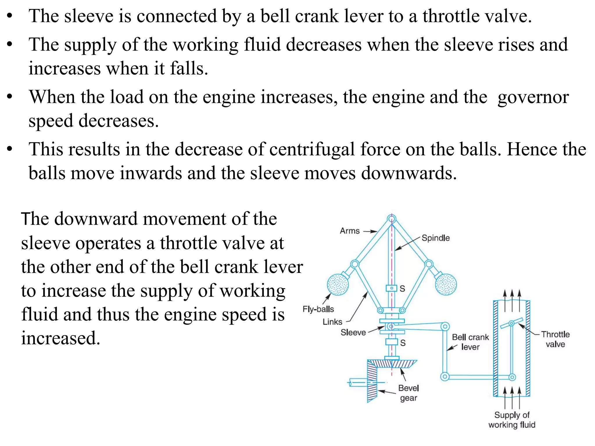


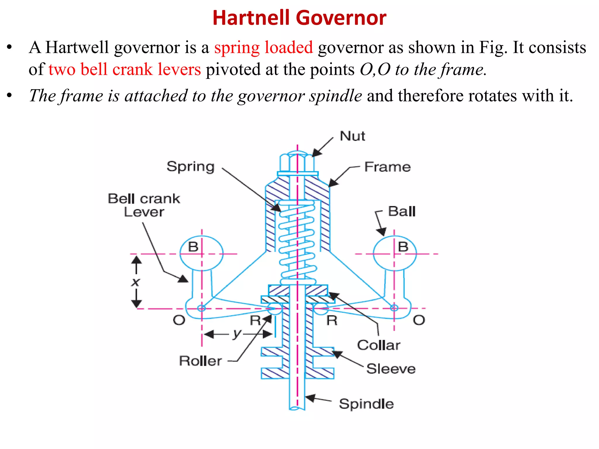


This document provides an overview of governors and their functions. It discusses the main components and workings of centrifugal governors, including Porter and Hartnell governors. The key points covered are: - Governors regulate engine speed by automatically controlling the supply of working fluid as load conditions vary. - Centrifugal governors work by balancing the centrifugal force on rotating balls with a controlling force. Porter governors use a central load while Hartnell governors use springs. - Other topics discussed include stability, sensitivity, isochronism, effort/power, and hunting in governors. Terms like height, equilibrium speed, and sleeve lift are also defined.


![Mechanics of machines ii [159533]](https://cdn.slidesharecdn.com/ss_thumbnails/eqcuqcsctmmlwdqr1k8i-signature-561ae61528e89c87b5e046ae92c4f43fe3c9e05593c8aae419f52d477405ade4-poli-160512171914-thumbnail.jpg?width=640&height=640&fit=bounds)