
Downloaded 183 times
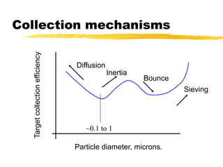
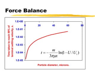
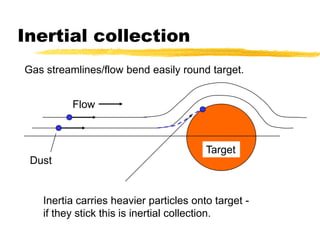
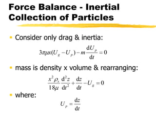
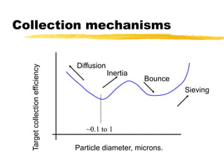
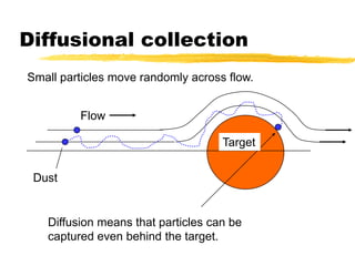
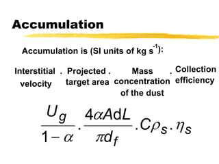
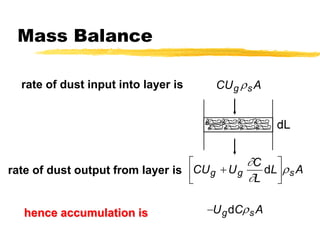
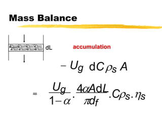
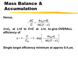
The document discusses gas cleaning techniques in the context of particle technology, focusing on collection mechanisms such as inertia, diffusion, and bouncing. It provides details on efficiency calculations, particularly for fibrous filters and electrostatic precipitators, and outlines the principles of inertia as applied to gas cleaning systems. Additionally, it includes references and resources for further study, as well as acknowledgments related to the content's creation and licensing.


