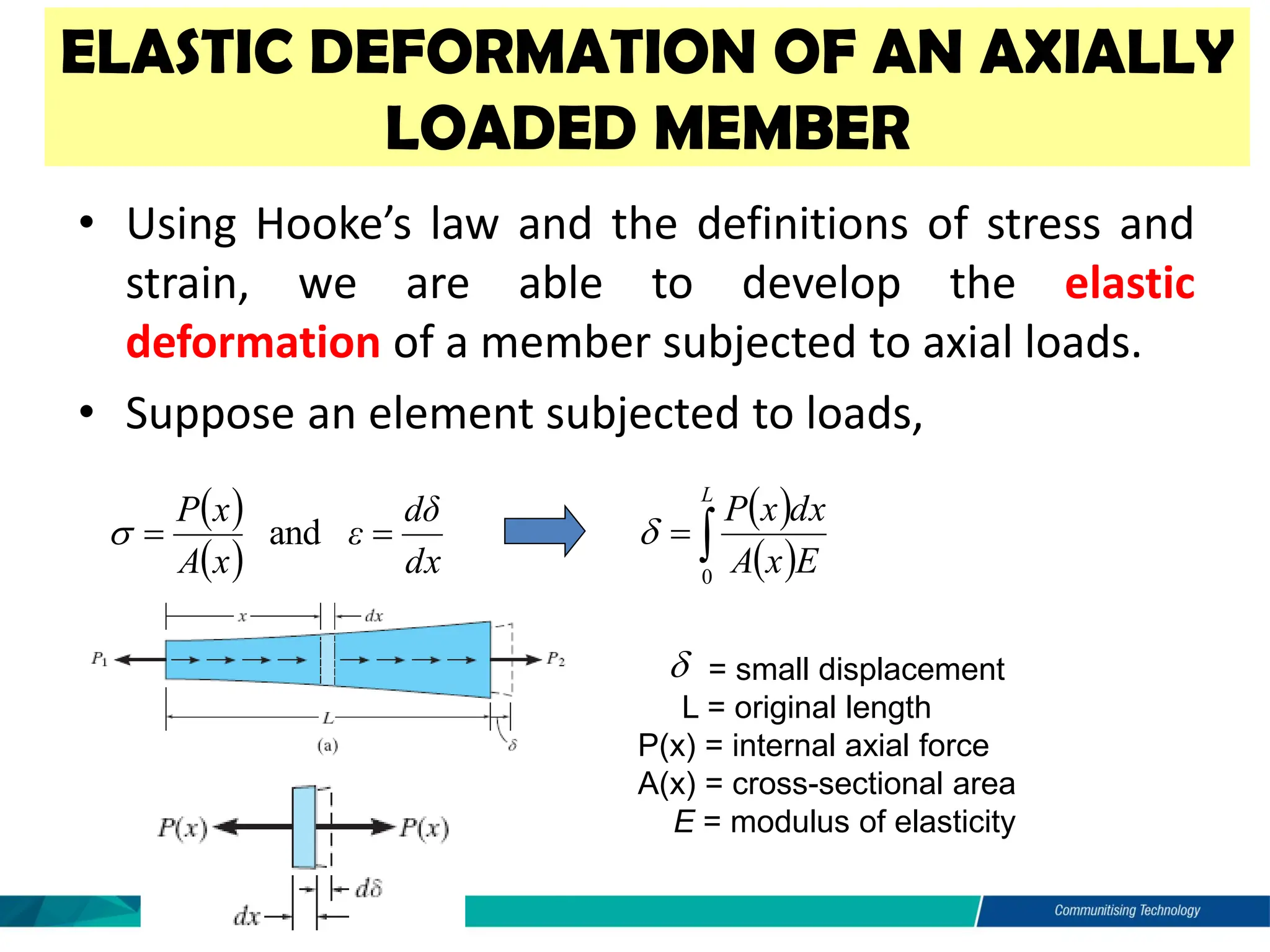
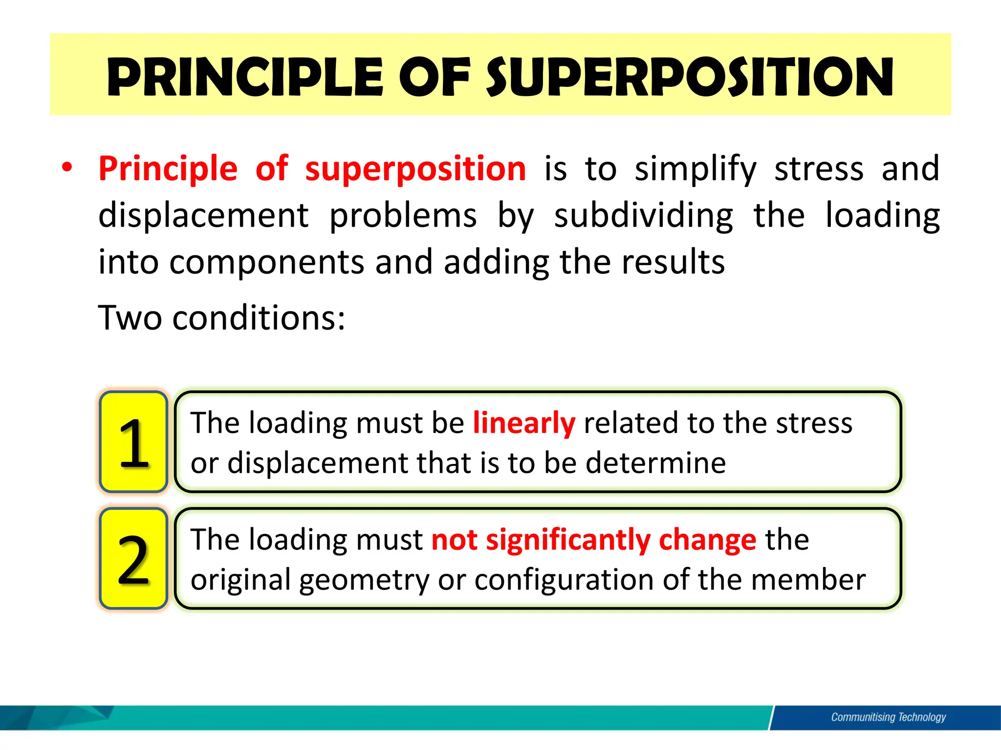
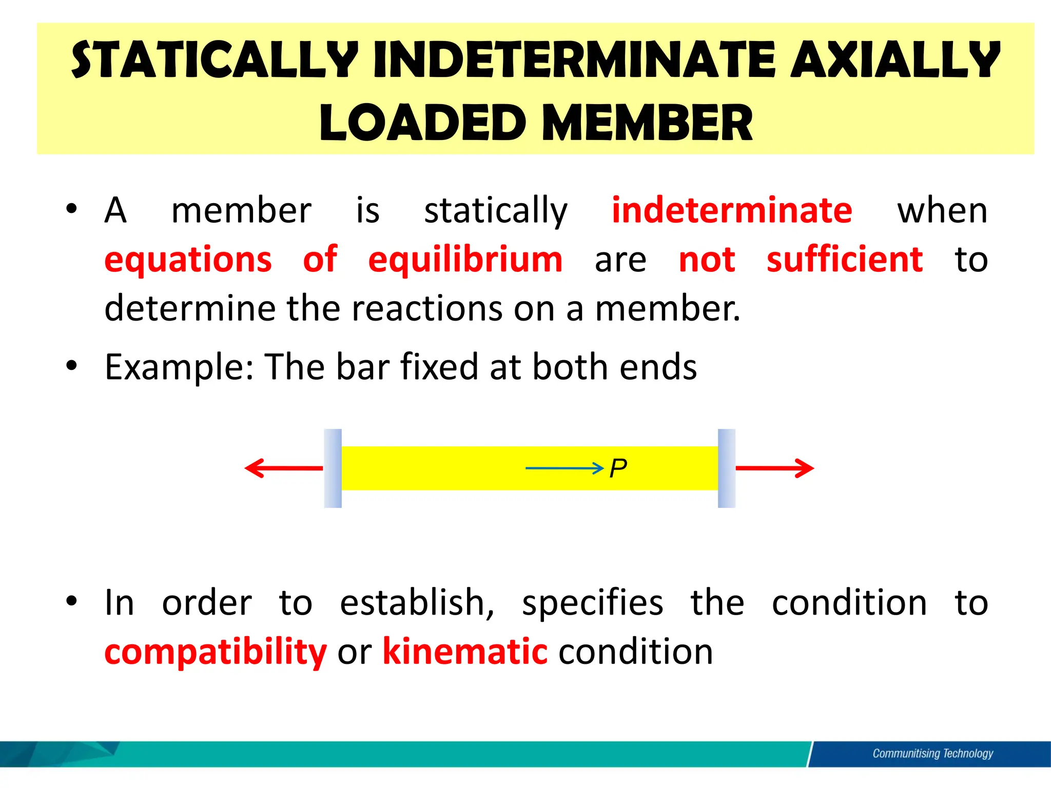
MECHANICS OF
MATERIALS
CHAPTER 4: AXIAL LOAD
LEARNING OUTCOME
• Define the elastic deformation of an axially loaded prismatic
bar
• Define the multiple prismatic bars
• Define the principle of superposition
• Define the Saint – Venant’s principle
• Calculate the deformations of member under axial load
• Calculate the deformations of member for stepped composite
bar
• Analyse the deformations in systems of axially loaded bars
• Analyse the deformations of member for statically
indeterminate assemblies.
• Calculate the deformation of member due to temperature
effect.
INTRODUCTION
• In Chapter 1, the concept of stress was developed as
a mean of measuring the force distribution within a
body
• In Chapter 2, the concept of strain was introduced to
describe the deformation produced in a body
• In Chapter 3, discussed the behavior of typical
engineering materials and how this behavior can be
idealized by equation that relate stress and strain
• In this chapter, discussed two general approaches
used to investigated a wide variety of structural
member subjected to axial loading and deformation
SAINT-VENANT’S PRINCIPLE
• Saint-Venant’s principle states that both localized
deformation and stress tend to “even out” at a
distance sufficiently removed from these regions.
ELASTIC DEFORMATION OF AN AXIALLY
LOADED MEMBER
• Using Hooke’s law and the definitions of stress and
strain, we are able to develop the elastic
deformation of a member subjected to axial loads.
• Suppose an element subjected to loads,
( )
( ) dx
dδ
ε
x
A
x
P
=
= and

( )
( )

=
L
E
x
A
dx
x
P
0

= small displacement
L = original length
P(x) = internal axial force
A(x) = cross-sectional area
E = modulus of elasticity

Constant Load and Cross-Sectional Area
• When a constant external force is applied at each
end of the member,
Sign Convention
• Force and displacement is positive when tension and
elongation and negative will be compression and
contraction.
AE
PL
=

Displacement
Example 1
Try this
Take diameter as 25 mm and modulus of elasticity is 200 GPa.
Example 2
The assembly consists of an aluminum tube AB having a cross-
sectional area of 400 mm2. A steel rod having a diameter of 10 mm is
attached to a rigid collar and passes through the tube. If a tensile
load of 80 kN is applied to the rod, determine the displacement of
the end C of the rod. Take Est = 200 GPa, Eal = 70 GPa
Try this
The assembly consists of steel road CB and an aluminium rod BA, each
having a diameter of 12mm. If the rod is subjected to the axial loadings at A
and at the coupling B, determine the displacement of the coupling B and the
end A. the unstretched length of each segment is as shown. Neglect the size
of the connections at B and C, and assume that they are rigid. Est = 200GPa,
Eal = 70 GPa
Try This
2 2 2
The composite shaft, consisting of aluminium, copper, and steel sections, is
subjected to the loading shown. Determine the displacement of end A with
respect to end D and the normal stress in each section. The cross-sectional
area and modulus of elasticity for each section are shown in the figure.
Neglect the size of the collars at B and C.
• Principle of superposition is to simplify stress and
displacement problems by subdividing the loading
into components and adding the results
• Two conditions:
PRINCIPLE OF SUPERPOSITION
The loading must be linearly related to the stress
or displacement that is to be determine
1
The loading must not significantly change the
original geometry or configuration of the member
2
STATICALLY INDETERMINATE AXIALLY
LOADED MEMBER
• A member is statically indeterminate when
equations of equilibrium are not sufficient to
determine the reactions on a member.
• Example: The bar fixed at both ends
• In order to establish, specifies the condition to
compatibility or kinematic condition
P
FA FB
Example 3
The steel rod has a diameter of 5 mm. It is attached to the fixed wall at A, and before it is
loaded, there is a gap between the wall at and B’ and the rod of 1 mm. Find the reactions at
A and B’ if the rod is subjected to an axial force of P = 20 kN. Neglect the size of the collar at
C. (Est = 200 GPa)
Example 4
The bolt is made of 2014-T6 aluminum alloy and is tightened so it compresses a
cylindrical tube made of Am 1004-T61 magnesium alloy. The tube has an outer
radius of 10 mm, and both the inner radius of the tube and the radius of the bolt are
5 mm. The washers at the top and bottom of the tube are considered to be rigid and
have a negligible thickness. Initially the nut is hand-tightened slightly; then, using a
wrench, the nut is further tightened one-half turn. If the bolt has 20 threads per inch,
determine the stress in the bolt.
Solution:
(1)
0
;
0 =
−
=

+  t
b
y F
F
F
( ) b
t 
 −
=

+ 5
.
0
Equilibrium requires
When the nut is tightened on the bolt, the tube will shorten.
Taking the 2 modulus of elasticity,
Solution:
( )
  ( )
 
( )
  ( )
 
( ) (2)
9
1125
125
5
10
75
5
60
5
.
0
10
45
5
10
60
3
2
3
2
2
b
t
b
t
F
F
F
F
−
=
−
=
−



kN
56
.
31
31556 =
=
= t
b F
F
The stresses in the bolt and tube are therefore
Solving Eqs. 1 and 2 simultaneously, we get
( )
( ) (Ans)
MPa
9
.
133
N/mm
9
.
133
5
10
31556
(Ans)
MPa
8
.
401
N/mm
8
.
401
5
31556
2
2
2
2
=
=
−
=
=
=
=
=
=




t
t
s
b
b
b
A
F
A
F
Example 5
• Change in temperature cause a material to change its
dimensions
• Since the material is homogeneous and isotropic
THERMAL STRESS
 = linear coefficient of thermal expansion, property of the material
T = algebraic change in temperature of the member
T = original length of the member
 = algebraic change in length of the member
TL
T 
−
= 

Example 4.12
The rigid bar is fixed to the top of the three posts made of A-36 steel and 2014-T6
aluminum. The posts each have a length of 250 mm when no load is applied to the
bar, and the temperature is T1 = 20°C. Determine the force supported by each
post if the bar is subjected to a uniform distributed load of 150 kN/m and the
temperature is raised to T2 = 80°C.
Solution:
( ) (2)
al
st 
 =

+
( ) (1)
0
10
90
2
;
0 3
=
−
+
=

+  al
st
y F
F
F
From free-body diagram we have
The top of each post is displaced by an equal amount and hence,
The final position of the top of each post is equal to its displacement caused by the
temperature increase and internal axial compressive force.
Solution:
( ) ( ) ( ) ( )F
al
T
st
F
st
T
st 


 +
−
=
+
−
( ) ( ) ( )
( ) ( ) ( )F
al
T
al
al
F
st
T
st
st






+
−
=

+
+
−
=

+
Applying Eq. 2 gives
With reference from the material properties, we have
( )
 ( )( ) ( )
( ) ( )
 
( )
 ( )( ) ( )
( ) ( )
 
( ) (3)
10
9
.
165
216
.
1
10
1
.
73
03
.
0
25
.
0
25
.
0
20
80
10
23
10
200
02
.
0
25
.
0
25
.
0
20
80
10
12
3
9
2
6
9
2
6
−
=
+
−
−
=
+
−
− −
−
al
st
al
st
F
F
F
F


Solving Eqs. 1 and 3 simultaneously yields (Ans)
kN
123
and
kN
4
.
16 =
−
= al
st F
F
THANK YOU

CHAPTER 4 - Mechanics of metarial UMP.pdf

  • 1.
  • 2.
    LEARNING OUTCOME • Definethe elastic deformation of an axially loaded prismatic bar • Define the multiple prismatic bars • Define the principle of superposition • Define the Saint – Venant’s principle • Calculate the deformations of member under axial load • Calculate the deformations of member for stepped composite bar • Analyse the deformations in systems of axially loaded bars • Analyse the deformations of member for statically indeterminate assemblies. • Calculate the deformation of member due to temperature effect.
  • 3.
    INTRODUCTION • In Chapter1, the concept of stress was developed as a mean of measuring the force distribution within a body • In Chapter 2, the concept of strain was introduced to describe the deformation produced in a body • In Chapter 3, discussed the behavior of typical engineering materials and how this behavior can be idealized by equation that relate stress and strain • In this chapter, discussed two general approaches used to investigated a wide variety of structural member subjected to axial loading and deformation
  • 4.
    SAINT-VENANT’S PRINCIPLE • Saint-Venant’sprinciple states that both localized deformation and stress tend to “even out” at a distance sufficiently removed from these regions.
  • 5.
    ELASTIC DEFORMATION OFAN AXIALLY LOADED MEMBER • Using Hooke’s law and the definitions of stress and strain, we are able to develop the elastic deformation of a member subjected to axial loads. • Suppose an element subjected to loads, ( ) ( ) dx dδ ε x A x P = = and  ( ) ( )  = L E x A dx x P 0  = small displacement L = original length P(x) = internal axial force A(x) = cross-sectional area E = modulus of elasticity 
  • 6.
    Constant Load andCross-Sectional Area • When a constant external force is applied at each end of the member, Sign Convention • Force and displacement is positive when tension and elongation and negative will be compression and contraction. AE PL =  Displacement
  • 7.
  • 8.
    Try this Take diameteras 25 mm and modulus of elasticity is 200 GPa.
  • 9.
    Example 2 The assemblyconsists of an aluminum tube AB having a cross- sectional area of 400 mm2. A steel rod having a diameter of 10 mm is attached to a rigid collar and passes through the tube. If a tensile load of 80 kN is applied to the rod, determine the displacement of the end C of the rod. Take Est = 200 GPa, Eal = 70 GPa
  • 10.
    Try this The assemblyconsists of steel road CB and an aluminium rod BA, each having a diameter of 12mm. If the rod is subjected to the axial loadings at A and at the coupling B, determine the displacement of the coupling B and the end A. the unstretched length of each segment is as shown. Neglect the size of the connections at B and C, and assume that they are rigid. Est = 200GPa, Eal = 70 GPa
  • 11.
    Try This 2 22 The composite shaft, consisting of aluminium, copper, and steel sections, is subjected to the loading shown. Determine the displacement of end A with respect to end D and the normal stress in each section. The cross-sectional area and modulus of elasticity for each section are shown in the figure. Neglect the size of the collars at B and C.
  • 12.
    • Principle ofsuperposition is to simplify stress and displacement problems by subdividing the loading into components and adding the results • Two conditions: PRINCIPLE OF SUPERPOSITION The loading must be linearly related to the stress or displacement that is to be determine 1 The loading must not significantly change the original geometry or configuration of the member 2
  • 13.
    STATICALLY INDETERMINATE AXIALLY LOADEDMEMBER • A member is statically indeterminate when equations of equilibrium are not sufficient to determine the reactions on a member. • Example: The bar fixed at both ends • In order to establish, specifies the condition to compatibility or kinematic condition P FA FB
  • 14.
    Example 3 The steelrod has a diameter of 5 mm. It is attached to the fixed wall at A, and before it is loaded, there is a gap between the wall at and B’ and the rod of 1 mm. Find the reactions at A and B’ if the rod is subjected to an axial force of P = 20 kN. Neglect the size of the collar at C. (Est = 200 GPa)
  • 15.
    Example 4 The boltis made of 2014-T6 aluminum alloy and is tightened so it compresses a cylindrical tube made of Am 1004-T61 magnesium alloy. The tube has an outer radius of 10 mm, and both the inner radius of the tube and the radius of the bolt are 5 mm. The washers at the top and bottom of the tube are considered to be rigid and have a negligible thickness. Initially the nut is hand-tightened slightly; then, using a wrench, the nut is further tightened one-half turn. If the bolt has 20 threads per inch, determine the stress in the bolt.
  • 16.
    Solution: (1) 0 ; 0 = − =  + t b y F F F ( ) b t   − =  + 5 . 0 Equilibrium requires When the nut is tightened on the bolt, the tube will shorten.
  • 17.
    Taking the 2modulus of elasticity, Solution: ( )   ( )   ( )   ( )   ( ) (2) 9 1125 125 5 10 75 5 60 5 . 0 10 45 5 10 60 3 2 3 2 2 b t b t F F F F − = − = −    kN 56 . 31 31556 = = = t b F F The stresses in the bolt and tube are therefore Solving Eqs. 1 and 2 simultaneously, we get ( ) ( ) (Ans) MPa 9 . 133 N/mm 9 . 133 5 10 31556 (Ans) MPa 8 . 401 N/mm 8 . 401 5 31556 2 2 2 2 = = − = = = = = =     t t s b b b A F A F
  • 18.
  • 19.
    • Change intemperature cause a material to change its dimensions • Since the material is homogeneous and isotropic THERMAL STRESS  = linear coefficient of thermal expansion, property of the material T = algebraic change in temperature of the member T = original length of the member  = algebraic change in length of the member TL T  − =  
  • 20.
    Example 4.12 The rigidbar is fixed to the top of the three posts made of A-36 steel and 2014-T6 aluminum. The posts each have a length of 250 mm when no load is applied to the bar, and the temperature is T1 = 20°C. Determine the force supported by each post if the bar is subjected to a uniform distributed load of 150 kN/m and the temperature is raised to T2 = 80°C.
  • 21.
    Solution: ( ) (2) al st  =  + ( ) (1) 0 10 90 2 ; 0 3 = − + =  +  al st y F F F From free-body diagram we have The top of each post is displaced by an equal amount and hence,
  • 22.
    The final positionof the top of each post is equal to its displacement caused by the temperature increase and internal axial compressive force. Solution: ( ) ( ) ( ) ( )F al T st F st T st     + − = + − ( ) ( ) ( ) ( ) ( ) ( )F al T al al F st T st st       + − =  + + − =  + Applying Eq. 2 gives With reference from the material properties, we have ( )  ( )( ) ( ) ( ) ( )   ( )  ( )( ) ( ) ( ) ( )   ( ) (3) 10 9 . 165 216 . 1 10 1 . 73 03 . 0 25 . 0 25 . 0 20 80 10 23 10 200 02 . 0 25 . 0 25 . 0 20 80 10 12 3 9 2 6 9 2 6 − = + − − = + − − − − al st al st F F F F   Solving Eqs. 1 and 3 simultaneously yields (Ans) kN 123 and kN 4 . 16 = − = al st F F
  • 23.