Week Topic LearningOutcomes
9 Axial Loading – Stress
and Deformation
•Deformation under axial
loading for statically
determinate structures
It is expected that students are
able to:
•Draw FBD and calculate
normal stress and deformation
of uniform and multiple cross-
section bars under axial load.
Learning Outcome
3.
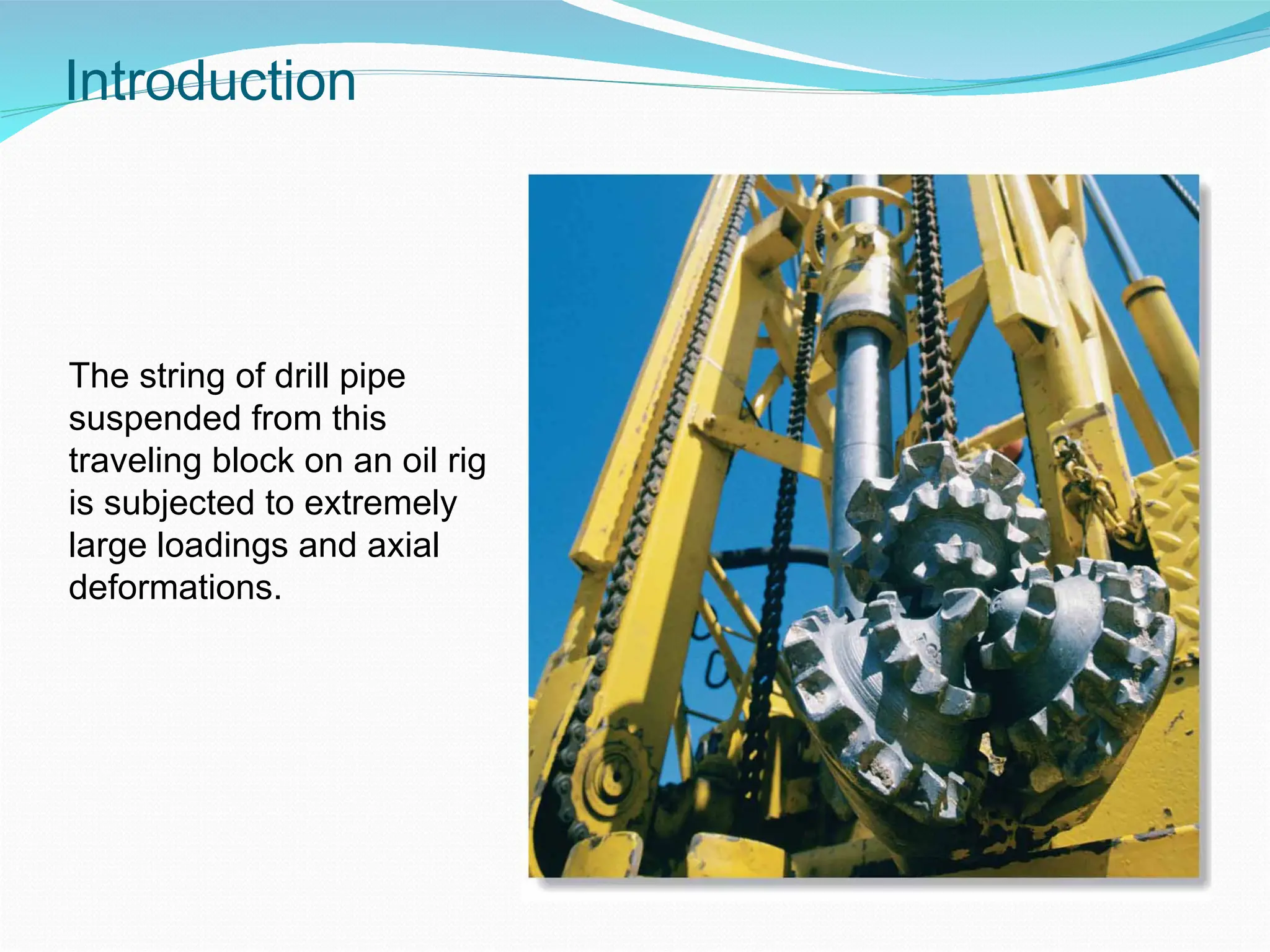
Introduction
The string ofdrill pipe
suspended from this
traveling block on an oil rig
is subjected to extremely
large loadings and axial
deformations.
4.
2 - 4
Stress& Strain: Loading and Deformation
• Suitability of a structure or machine depends on the deformations
in the structure as well as the stresses induced under loading.
Thus, statics analysis alone is not sufficient.
• Determination of the stress distribution within a member also
requires consideration of deformations in the member.
• Chapter 2 is concerned with axial loading and the deformation of a
structural member under axial load.
• Chapter 3 deals with torsional load and angle of twist.
• Chapter 4 deals with pure bending and normal stress caused by
bending (OMIT deformation)
5.
2 - 5
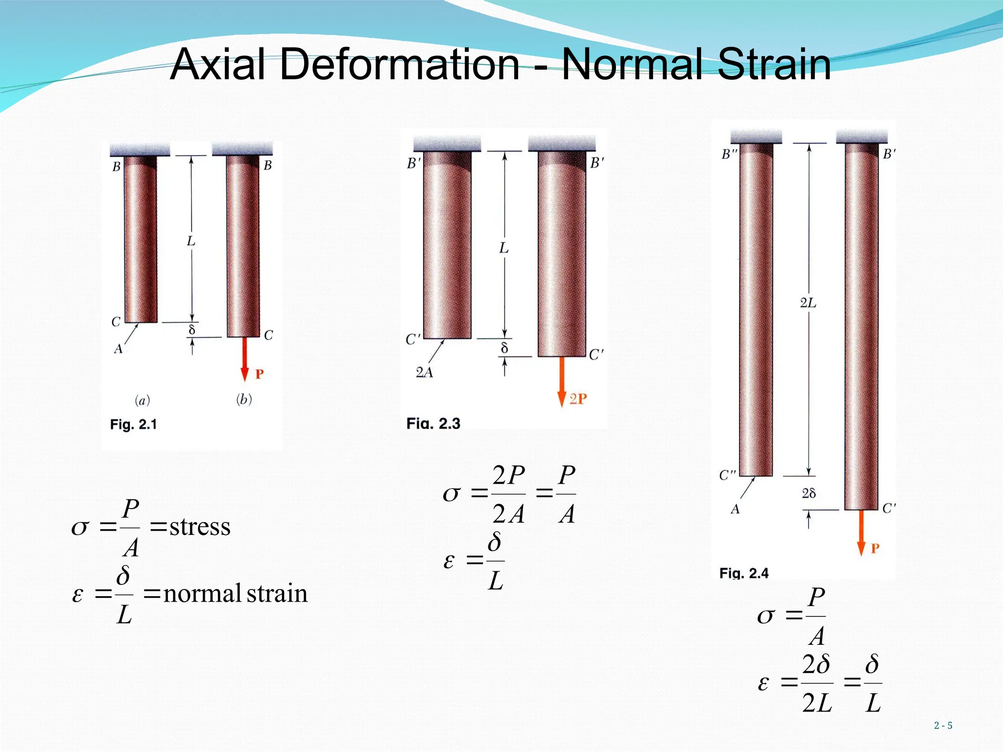
AxialDeformation - Normal Strain
strain
normal
stress
L
A
P
L
A
P
A
P
2
2
L
L
A
P
2
2
2 - 7
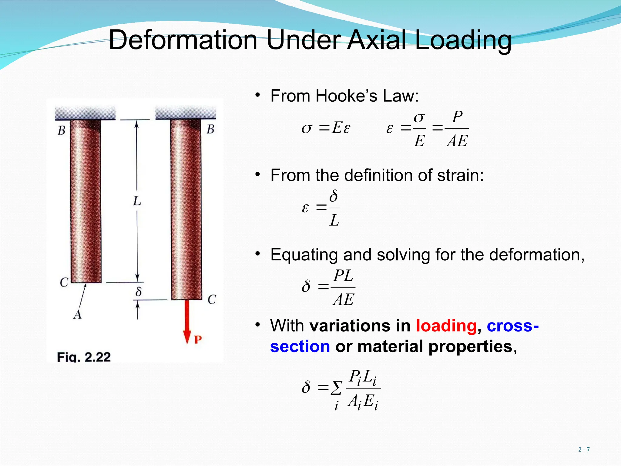
DeformationUnder Axial Loading
AE
P
E
E
• From Hooke’s Law:
• From the definition of strain:
L
• Equating and solving for the deformation,
AE
PL
• With variations in loading, cross-
section or material properties,
i i
i
i
i
E
A
L
P
8.
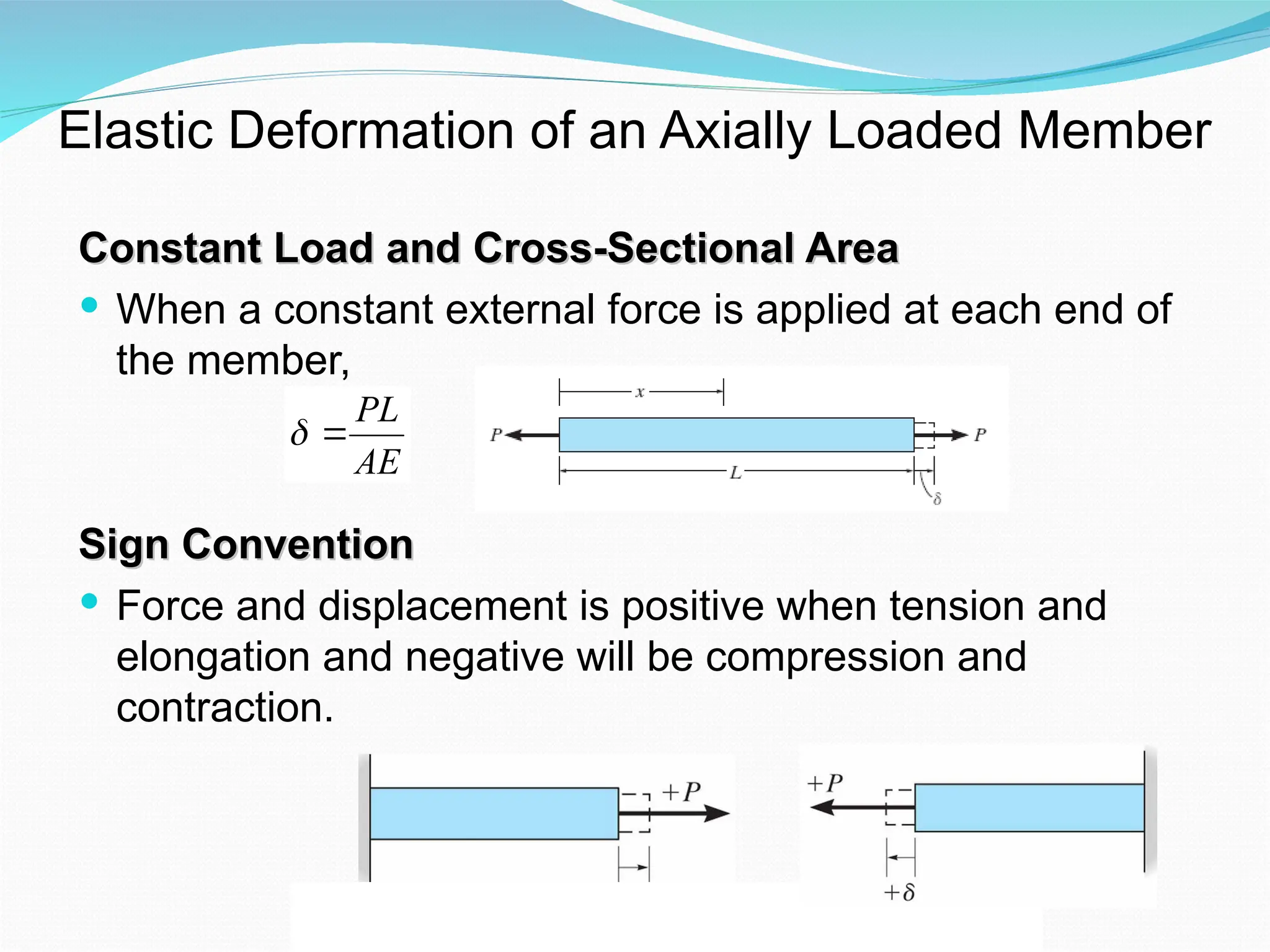
Elastic Deformation ofan Axially Loaded Member
Constant Load and Cross-Sectional Area
Constant Load and Cross-Sectional Area
When a constant external force is applied at each end of
the member,
Sign Convention
Sign Convention
Force and displacement is positive when tension and
elongation and negative will be compression and
contraction.
AE
PL
9.
2 - 9
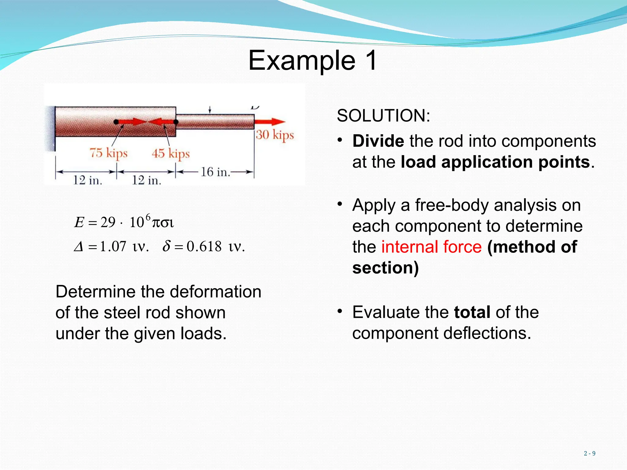
Example1
Determine the deformation
of the steel rod shown
under the given loads.
€
E = 29 × 106
psi
D = 1.07 in. d = 0.618 in.
SOLUTION:
• Divide the rod into components
at the load application points.
• Apply a free-body analysis on
each component to determine
the internal force (method of
section)
• Evaluate the total of the
component deflections.
10.
2 - 10
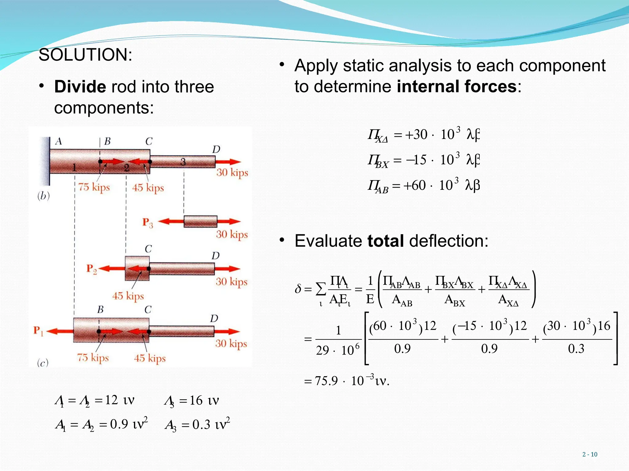
SOLUTION:
•Divide rod into three
components:
L
1 = L
2 = 12 in
A1 = A2 = 0.9 in2
L
3 = 16 in
A3 = 0.3 in2
• Apply static analysis to each component
to determine internal forces:
€
P
CD = +30 × 103
lb
P
BC = −
15 × 103
lb
P
AB = +60 × 103
lb
• Evaluate total deflection:
€
δ =
P
i
Li
AiEi
i
∑ =
1
E
P
ABLAB
AAB
+
P
BCLBC
ABC
+
P
CDLCD
ACD
⎛
⎝
⎜
⎞
⎠
⎟
=
1
29 × 106
60 × 103
( )12
0.9
+
−
15 × 103
( )12
0.9
+
30 × 103
( )16
0.3
⎡
⎣
⎢
⎢
⎤
⎦
⎥
⎥
= 75.9 × 10−
3
in.
11.
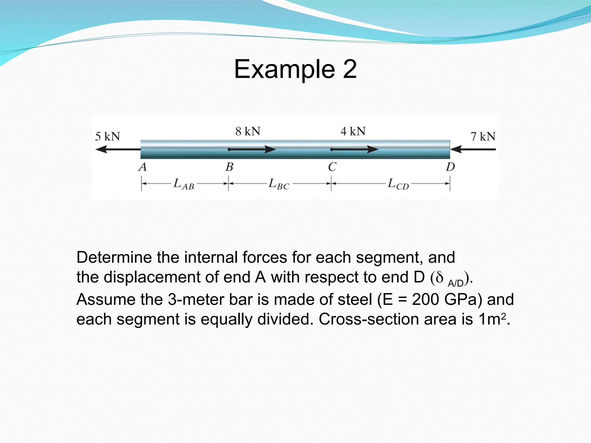
Example 2
Determine theinternal forces for each segment, and
the displacement of end A with respect to end D ( A/D).
Assume the 3-meter bar is made of steel (E = 200 GPa) and
each segment is equally divided. Cross-section area is 1m2
.
12.
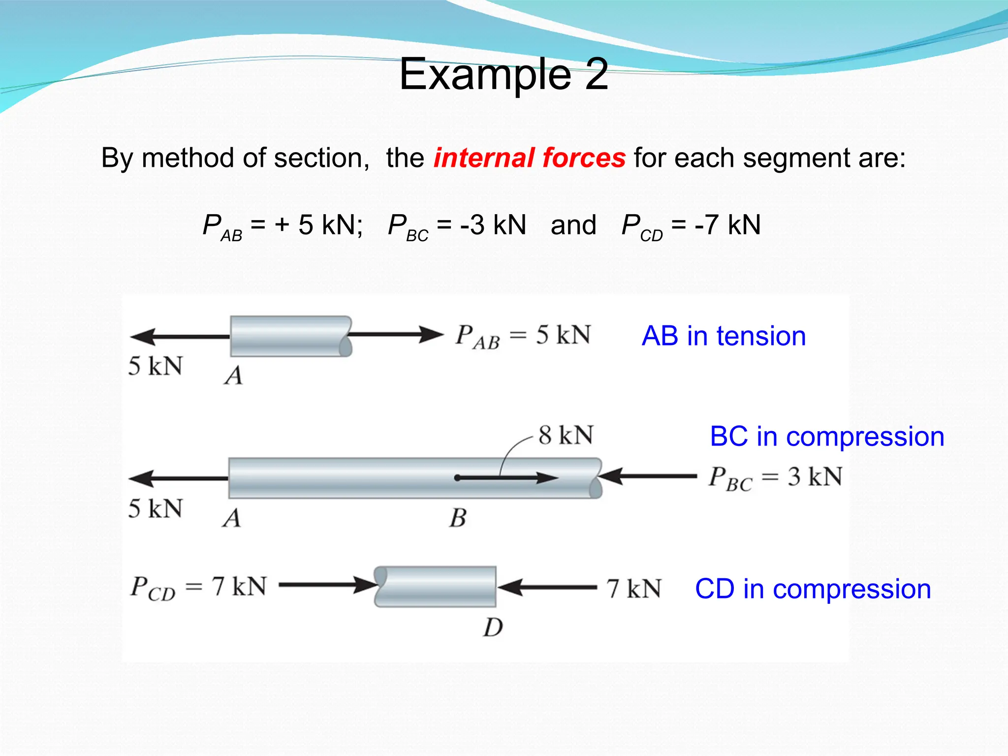
Example 2
By methodof section, the internal forces for each segment are:
PAB = + 5 kN; PBC = -3 kN and PCD = -7 kN
AB in tension
BC in compression
CD in compression
13.
Example 2
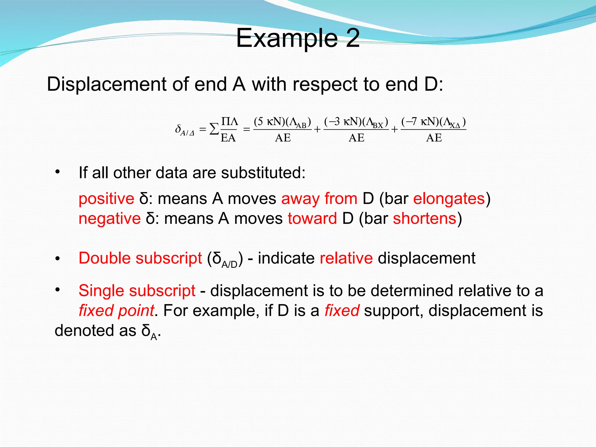
Displacement ofend A with respect to end D:
€
δA/D =
PL
EA
∑ =
(5 kN)(LAB)
AE
+
(−
3 kN)(LBC)
AE
+
(−
7 kN)(LCD )
AE
€
δA/D =
(1 m)
(200 × 109
N/m 2
)(1 m 2
)
5000 N + (−
3000 N) + (−
7000 N)
[ ]
14.
Example 2
Displacement ofend A with respect to end D:
€
δA/D =
PL
EA
∑ =
(5 kN)(LAB)
AE
+
(−
3 kN)(LBC)
AE
+
(−
7 kN)(LCD )
AE
• If all other data are substituted:
positive δ: means A moves away from D (bar elongates)
negative δ: means A moves toward D (bar shortens)
• Double subscript (δA/D) - indicate relative displacement
• Single subscript - displacement is to be determined relative to a
fixed point. For example, if D is a fixed support, displacement is
denoted as δA.
15.
2 - 15
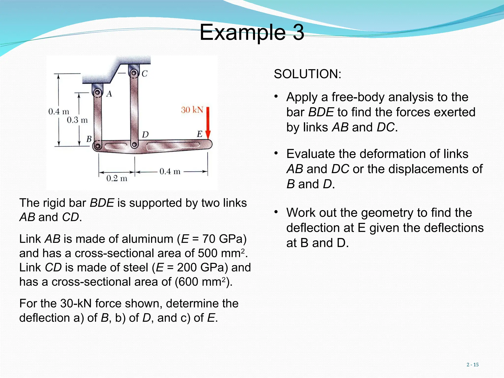
Example3
The rigid bar BDE is supported by two links
AB and CD.
Link AB is made of aluminum (E = 70 GPa)
and has a cross-sectional area of 500 mm2
.
Link CD is made of steel (E = 200 GPa) and
has a cross-sectional area of (600 mm2
).
For the 30-kN force shown, determine the
deflection a) of B, b) of D, and c) of E.
SOLUTION:
• Apply a free-body analysis to the
bar BDE to find the forces exerted
by links AB and DC.
• Evaluate the deformation of links
AB and DC or the displacements of
B and D.
• Work out the geometry to find the
deflection at E given the deflections
at B and D.
16.
2 - 16
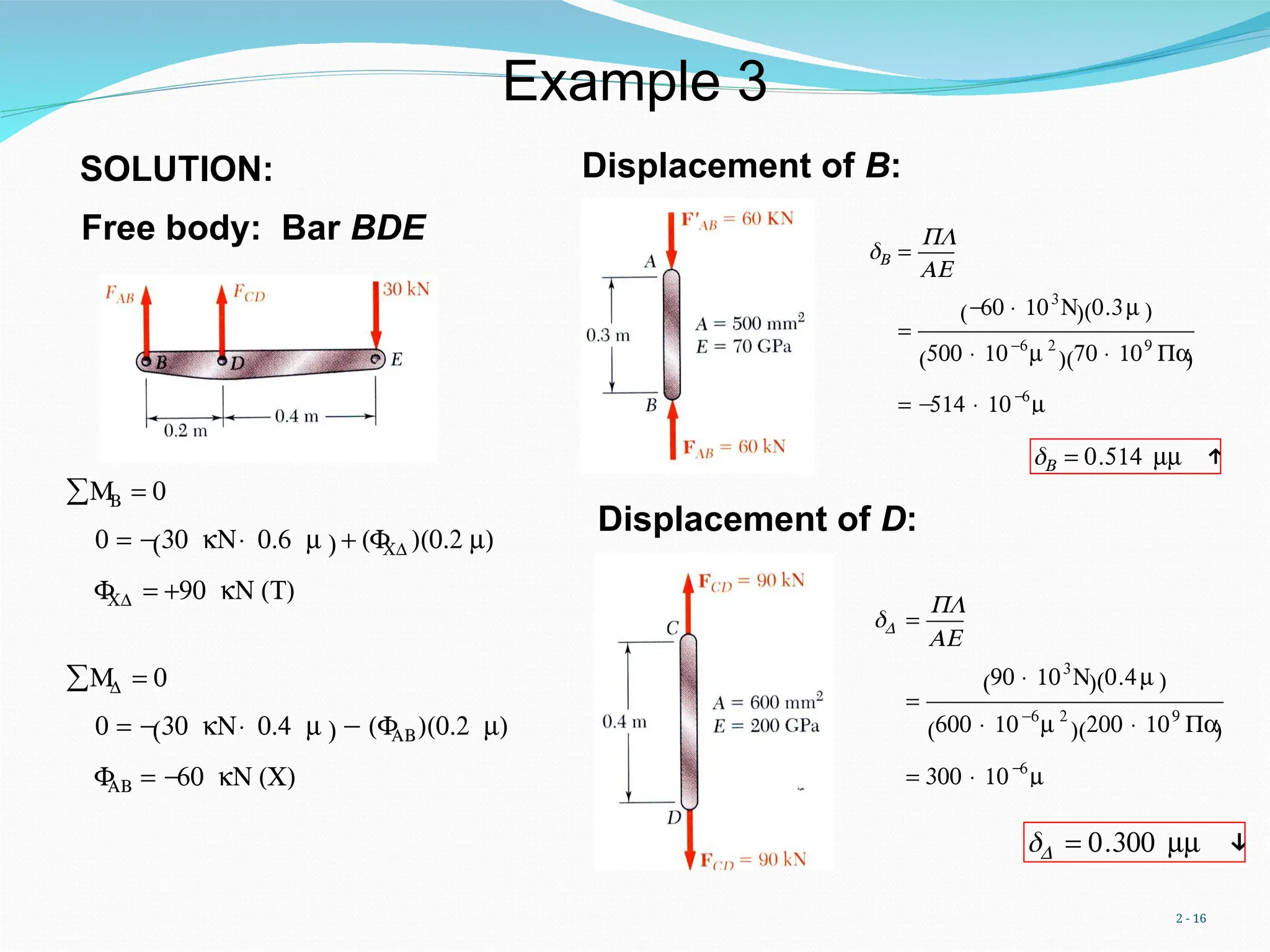
Displacementof B:
€
δB =
PL
AE
=
−
60 × 103
N
( ) 0.3m
( )
500 × 10-6
m 2
( ) 70 × 109
Pa
( )
= −
514 × 10−
6
m
€
δB = 0.514 mm ↑
Displacement of D:
€
δD =
PL
AE
=
90 × 103
N
( ) 0.4m
( )
600 × 10-6
m 2
( ) 200 × 109
Pa
( )
= 300 × 10−
6
m
δD = 0.300 mm ↓
Free body: Bar BDE
MB
∑ = 0
0 = −30 kN× 0.6 m
( ) + (F
CD )(0.2 m)
F
CD = +90 kN (T)
MD
∑ = 0
0 = −30 kN× 0.4 m
( ) − (F
AB)(0.2 m)
F
AB = −
60 kN (C)
SOLUTION:
Example 3
17.
2 - 17
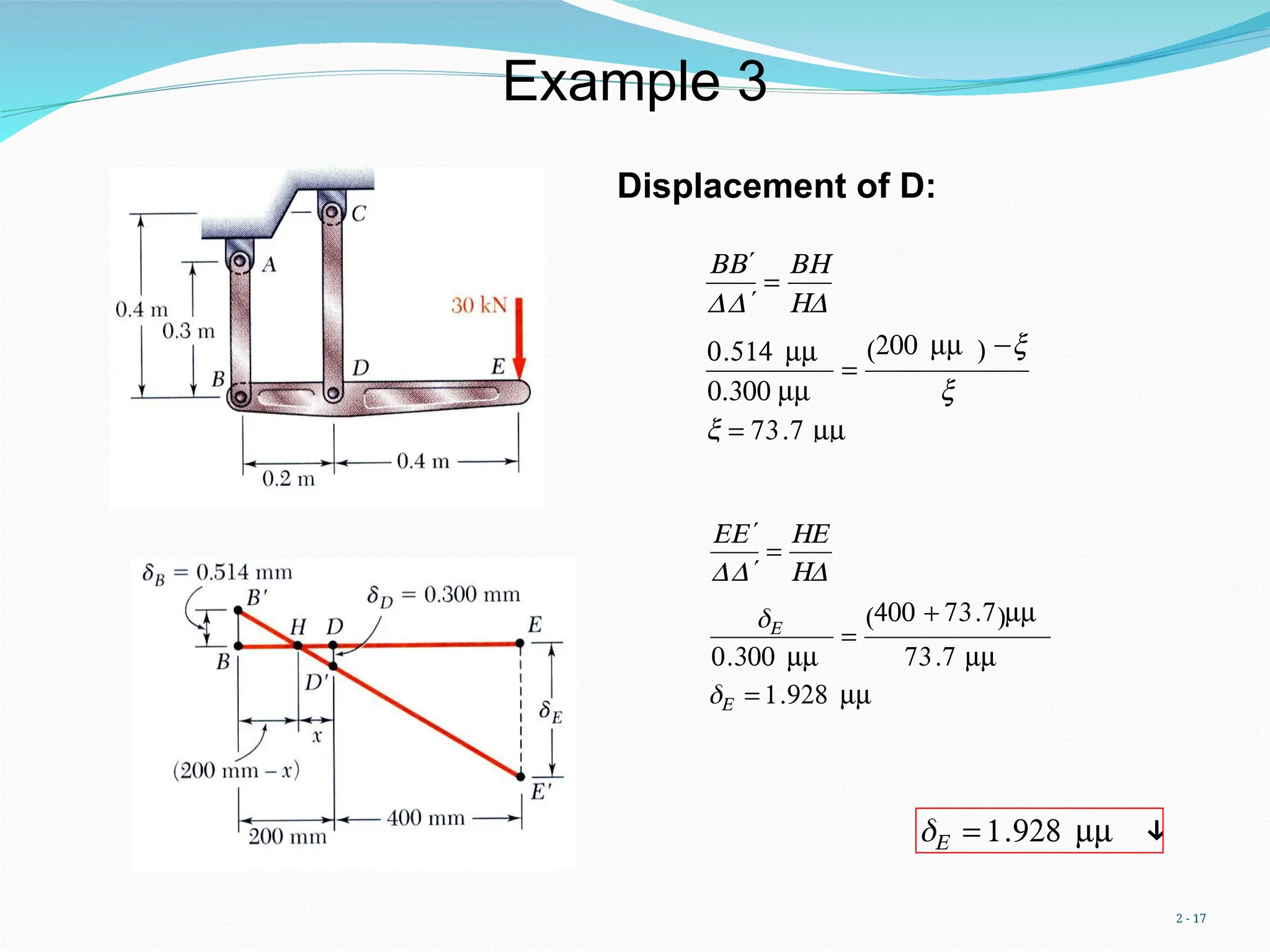
Displacementof D:
€
B ′
B
D ′
D
=
BH
HD
0.514 mm
0.300 mm
=
200 mm
( ) −x
x
x = 73.7 mm
δE = 1.928 mm ↓
€
E ′
E
D ′
D
=
HE
HD
δE
0.300 mm
=
400 + 73.7
( )mm
73.7 mm
δE = 1.928 mm
Example 3
18.
2 - 18
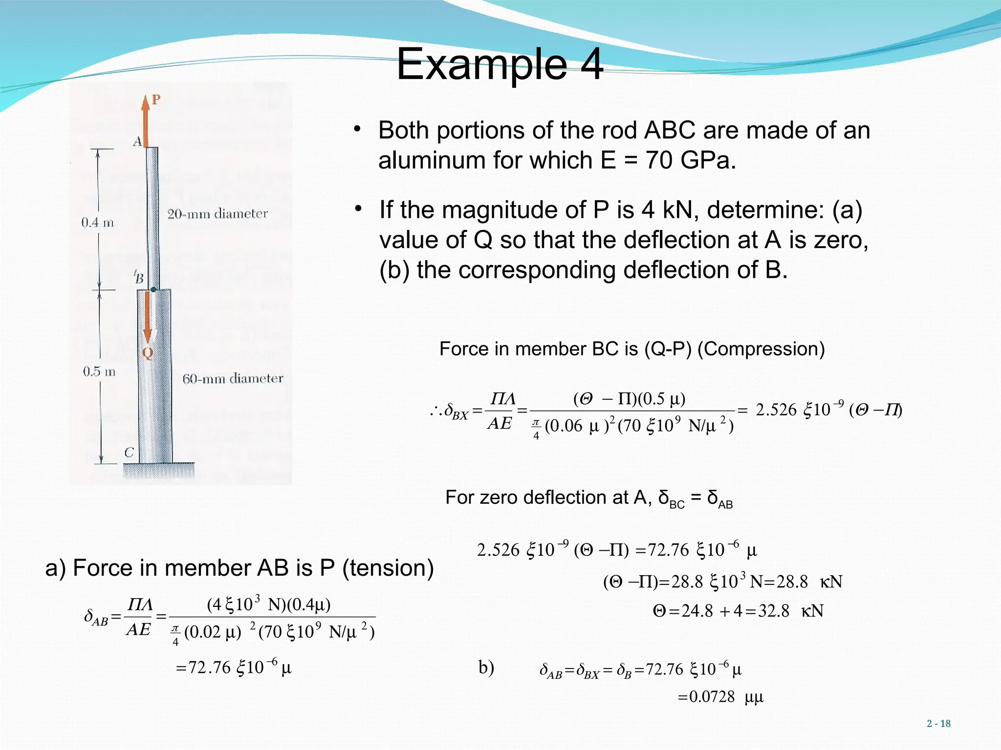
Example4
• Both portions of the rod ABC are made of an
aluminum for which E = 70 GPa.
• If the magnitude of P is 4 kN, determine: (a)
value of Q so that the deflection at A is zero,
(b) the corresponding deflection of B.
a) Force in member AB is P (tension)
€
δAB =
PL
AE
=
(4 x10³
N)(0.4m)
π
4
(0.02 m) 2
(70 x109
N/m 2
)
=72.76 x10−
6
m
Force in member BC is (Q-P) (Compression)
€
∴δBC =
PL
AE
=
(Q − P)(0.5 m)
π
4
(0.06 m )2
(70 x109
N/m 2
)
= 2.526 x10−
9
(Q −P)
For zero deflection at A, δBC = δAB
€
2.526 x10−
9
(Q −P) =72.76 x10−
6
m
(Q −P)=28.8 x10³
N=28.8 kN
Q =24.8 + 4 =32.8 kN
b) δAB =δBC = δB =72.76 x10−
6
m
=0.0728 mm
19.
2 - 19
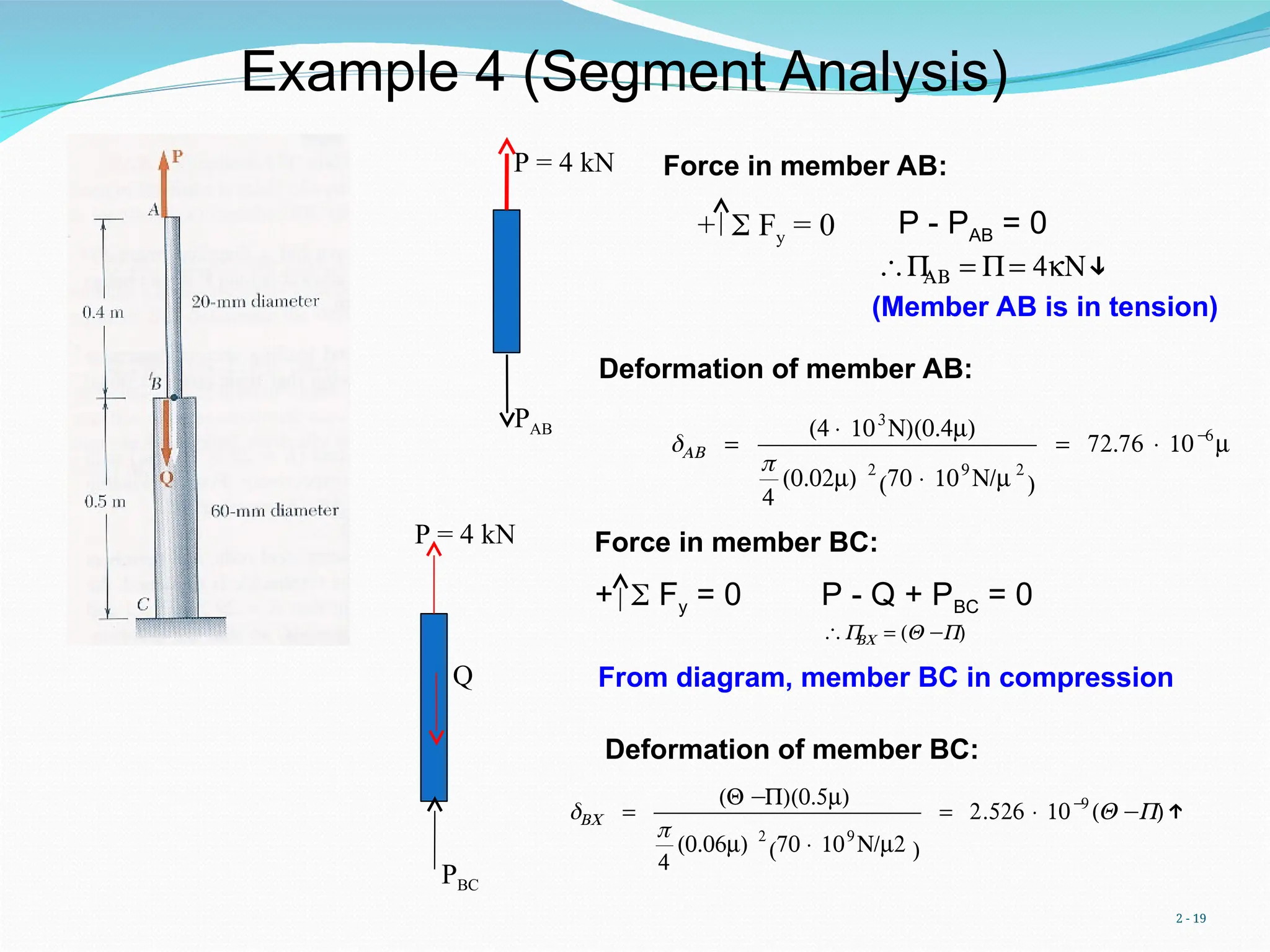
Example4 (Segment Analysis)
€
δAB =
(4 × 10³
N)(0.4m)
π
4
(0.02m) 2
70 × 109
N/m 2
( )
= 72.76 × 10−
6
m
Force in member BC:
+ Fy = 0
P = 4 kN
PAB
P - PAB = 0
€
∴P
AB = P= 4kN↓
(Member AB is in tension)
P = 4 kN
PBC
Q
+ Fy = 0 P - Q + PBC = 0
€
∴P
BC = (Q −P)
Deformation of member BC:
Deformation of member AB:
Force in member AB:
From diagram, member BC in compression
δBC =
(Q −P)(0.5m)
π
4
(0.06m) 2
70 × 109
N/m2
( )
= 2.526 × 10−
9
(Q −P)↑
20.
2 - 20
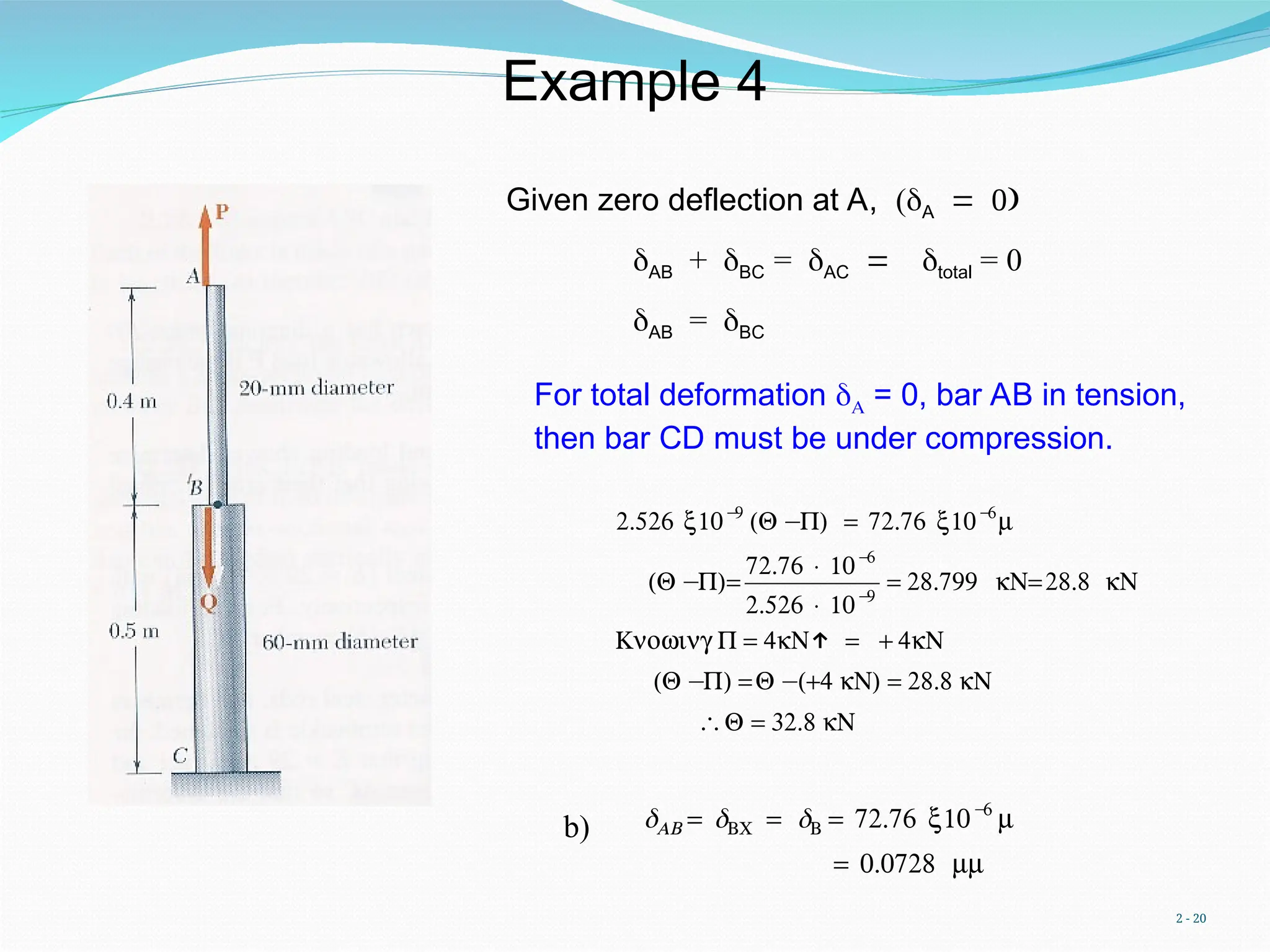
Givenzero deflection at A, (A
AB + BC = ACtotal = 0
AB = BC
€
2.526 x10−
9
(Q −P) = 72.76 x10−
6
m
(Q −P)=
72.76 × 10−
6
2.526 × 10−
9
= 28.799 kN=28.8 kN
Knowing P = 4kN↑ = + 4kN
(Q −P) =Q −(+4 kN) = 28.8 kN
∴Q = 32.8 kN
b) δAB = δBC = δB = 72.76 x10−
6
m
= 0.0728 mm
For total deformation = 0, bar AB in tension,
then bar CD must be under compression.
Example 4
21.
2 - 21
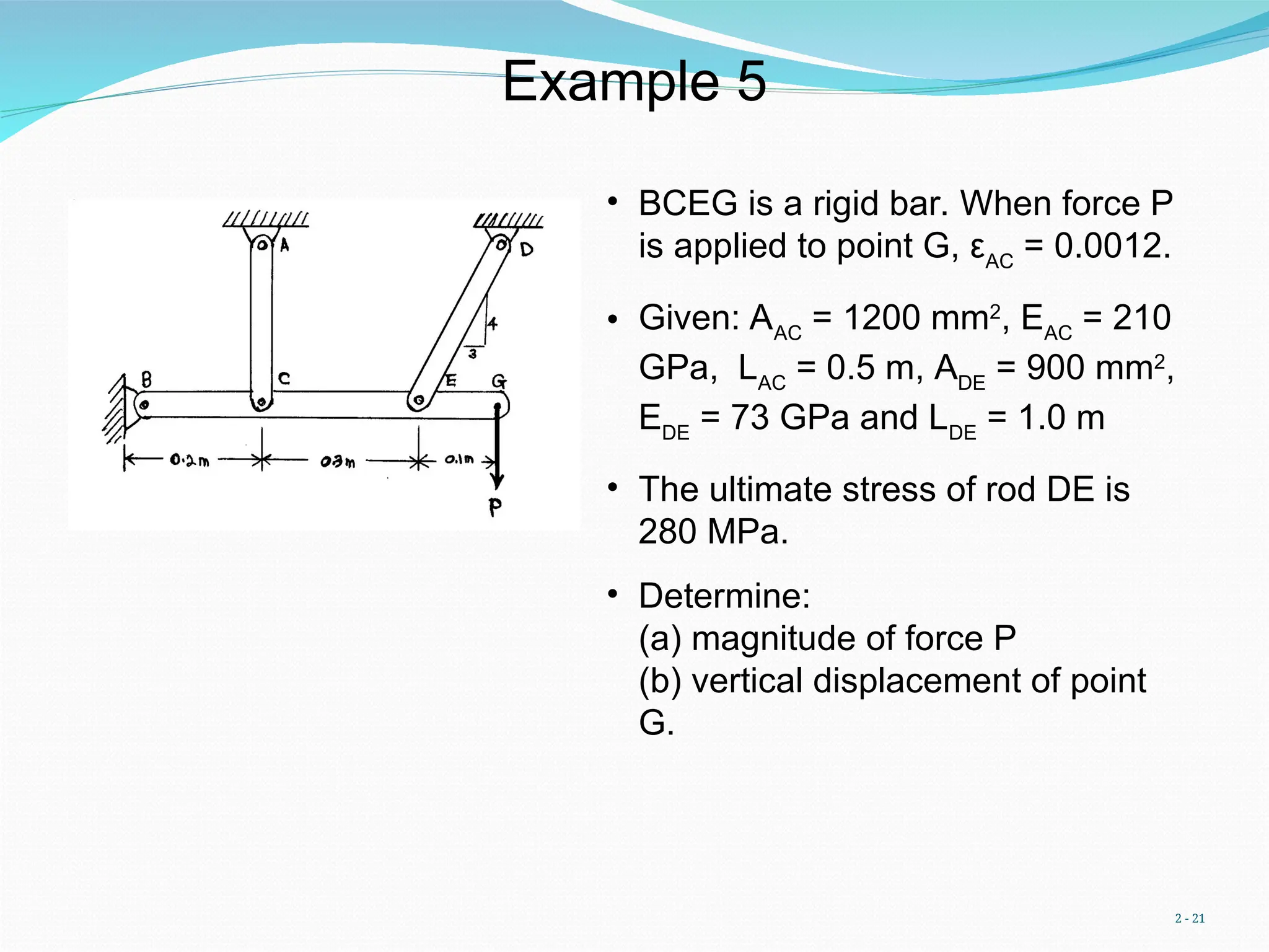
Example5
• BCEG is a rigid bar. When force P
is applied to point G, εAC
= 0.0012.
• Given: AAC
= 1200 mm2
, EAC
= 210
GPa, LAC
= 0.5 m, ADE
= 900 mm2
,
EDE
= 73 GPa and LDE
= 1.0 m
• The ultimate stress of rod DE is
280 MPa.
• Determine:
(a) magnitude of force P
(b) vertical displacement of point
G.
22.
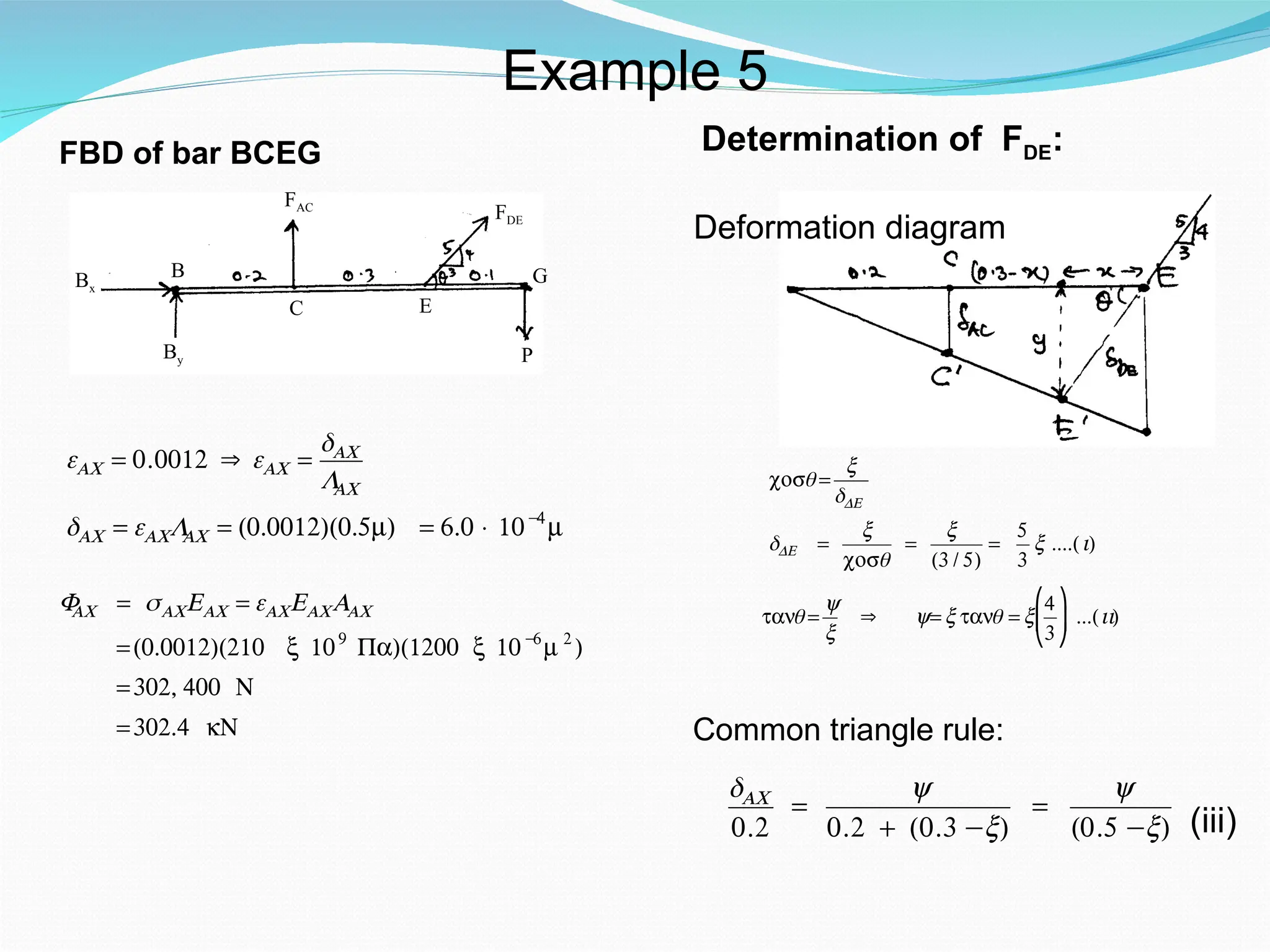
FBD of barBCEG
P
By
FAC
B
FDE
C E
G
Bx
εAC = 0.0012 ⇒ εAC =
δAC
L
AC
δAC = εACL
AC = (0.0012)(0.5m) = 6.0 × 10−
4
m
F
AC = σACEAC = εACEACAAC
=(0.0012)(210 x 109
Pa)(1200 x 10−
6
m 2
)
=302, 400 N
=302.4 kN
Deformation diagram
Determination of FDE:
€
cosθ =
x
δDE
δDE =
x
cosθ
=
x
(3 / 5)
=
5
3
x ....(i)
€
tanθ =
y
x
⇒ y= x tanθ = x
4
3
⎛
⎝
⎜
⎞
⎠
⎟ ...(ii)
Common triangle rule:
δAC
0.2
=
y
0.2 + (0.3 −x)
=
y
(0.5 −x) (iii)
Example 5
23.
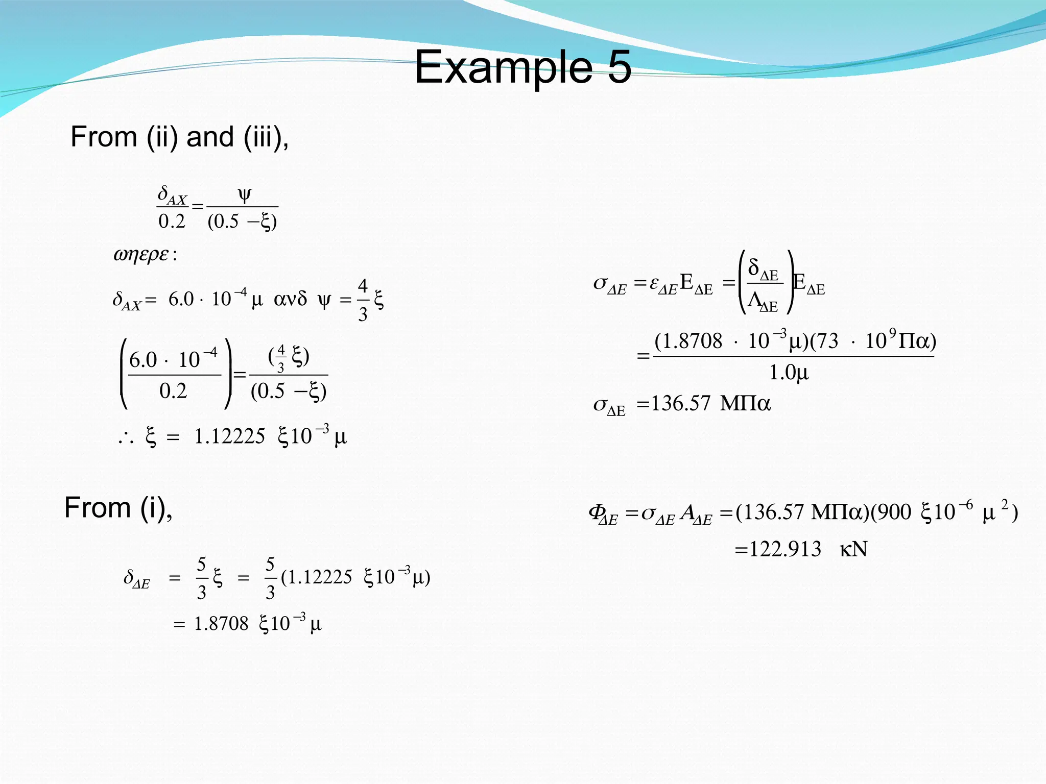
From (ii) and(iii),
€
δAC
0.2
=
y
(0.5 −x)
where :
δAC = 6.0 × 10−
4
m and y =
4
3
x
€
6.0 × 10−
4
0.2
⎛
⎝
⎜
⎜
⎞
⎠
⎟
⎟=
(4
3
x)
(0.5 −x)
∴ x = 1.12225 x10−
3
m
From (i),
€
δDE =
5
3
x =
5
3
(1.12225 x10−
3
m)
= 1.8708 x10−
3
m
€
σDE =εDE EDE =
dDE
LDE
⎛
⎝
⎜
⎞
⎠
⎟EDE
=
(1.8708 × 10−
3
m)(73 × 109
Pa)
1.0m
σDE =136.57 MPa
€
F
DE =σDE ADE =(136.57 MPa)(900 x10−
6
m 2
)
=122.913 kN
Example 5
24.
2 - 24
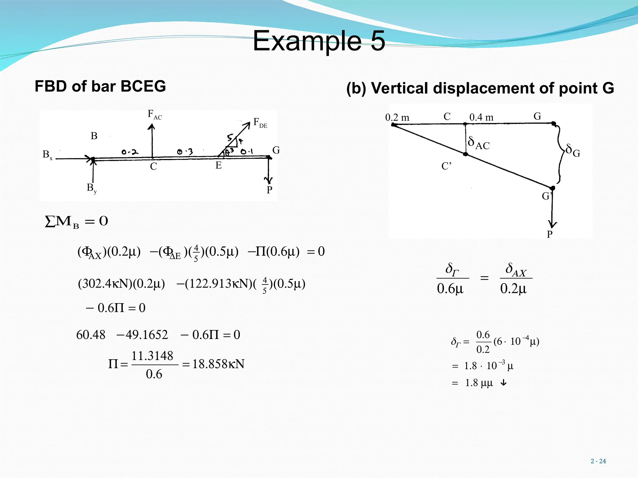
€
δG
0.6m
=
δAC
0.2m
€
δG=
0.6
0.2
(6 × 10−
4
m)
= 1.8 × 10−
3
m
= 1.8 mm ↓
(b) Vertical displacement of point G
G
G
G’
AC
C
C’
P
0.2 m 0.4 m
FBD of bar BCEG
P
By
FAC
B
FDE
C E
G
Bx
MB
∑ = 0
€
(F
AC)(0.2m) −(F
DE )(4
5
)(0.5m) −P(0.6m) = 0
€
(302.4kN)(0.2m) −(122.913kN)( 4
5
)(0.5m)
− 0.6P = 0
€
60.48 −49.1652 − 0.6P = 0
P =
11.3148
0.6
= 18.858kN
Example 5
25.
2 - 25
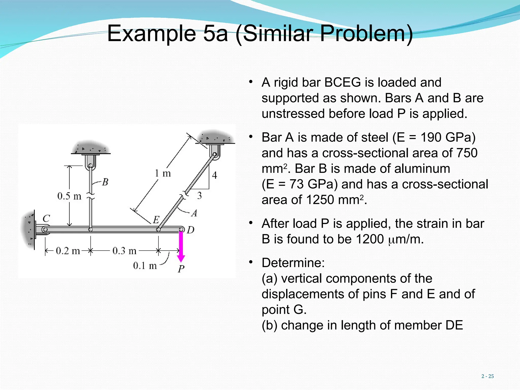
Example5a (Similar Problem)
• A rigid bar BCEG is loaded and
supported as shown. Bars A and B are
unstressed before load P is applied.
• Bar A is made of steel (E = 190 GPa)
and has a cross-sectional area of 750
mm2
. Bar B is made of aluminum
(E = 73 GPa) and has a cross-sectional
area of 1250 mm2
.
• After load P is applied, the strain in bar
B is found to be 1200 m/m.
• Determine:
(a) vertical components of the
displacements of pins F and E and of
point G.
(b) change in length of member DE
26.
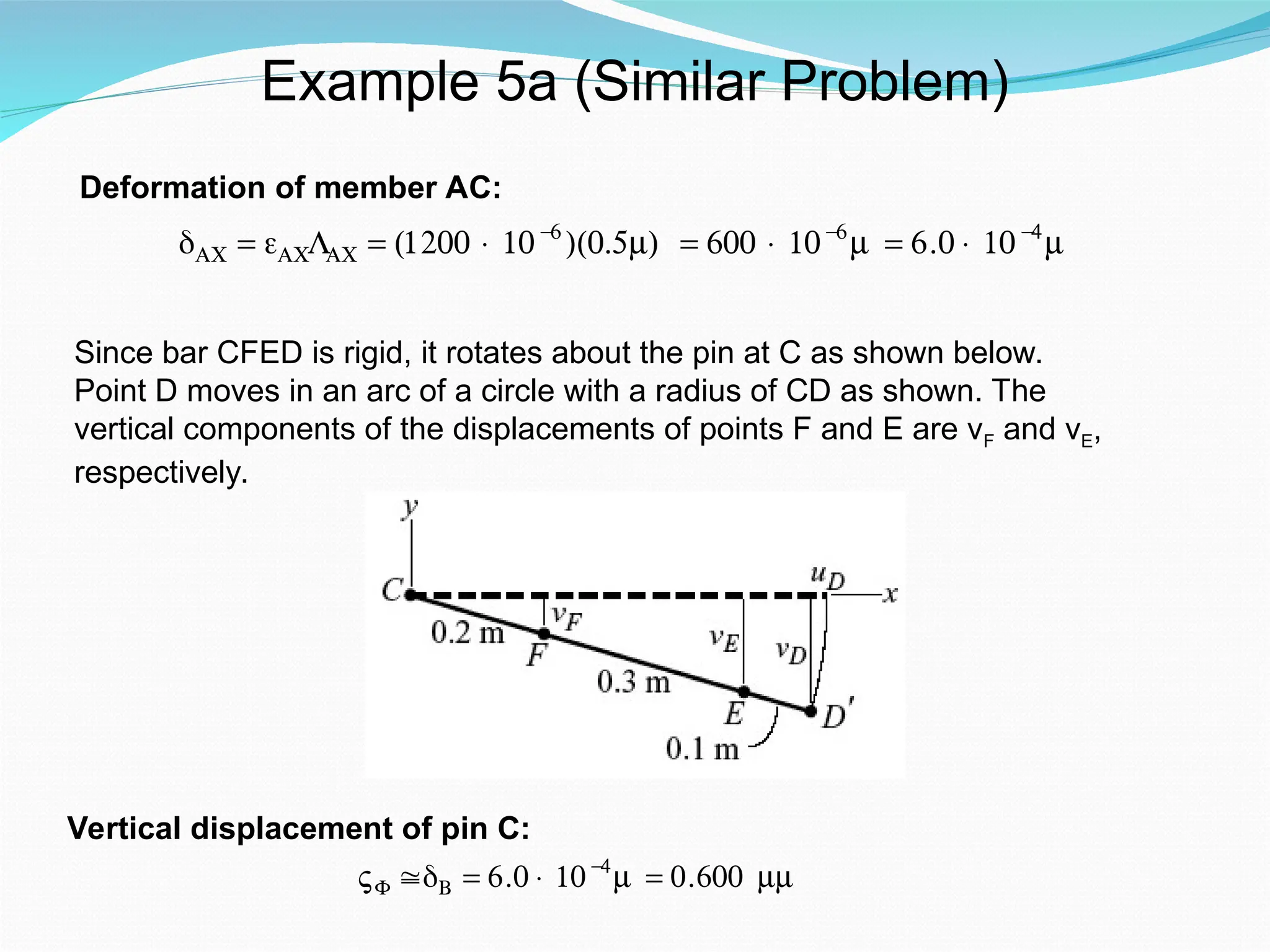
Example 5a (SimilarProblem)
€
δAC = εACLAC = (1200 × 10−
6
)(0.5m) = 600 × 10−
6
m = 6.0 × 10−
4
m
Deformation of member AC:
Since bar CFED is rigid, it rotates about the pin at C as shown below.
Point D moves in an arc of a circle with a radius of CD as shown. The
vertical components of the displacements of points F and E are νF and νE,
respectively.
VF ≅δB = 6.0 × 10−
4
m = 0.600 mm
Vertical displacement of pin C:
27.
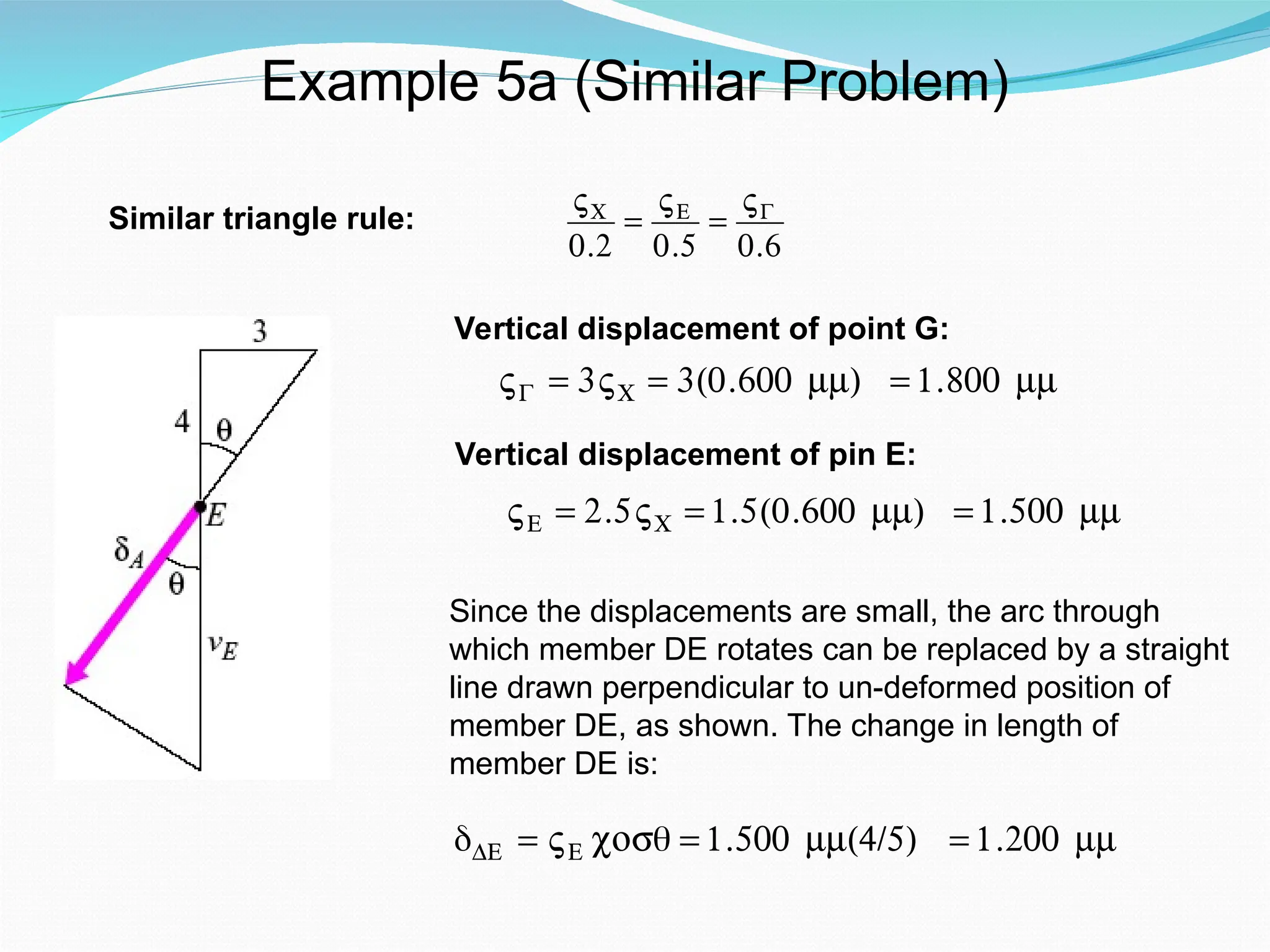
Example 5a (SimilarProblem)
Similar triangle rule:
€
VC
0.2
=
VE
0.5
=
VG
0.6
Vertical displacement of point G:
€
VG = 3VC = 3(0.600 mm) = 1.800 mm
Vertical displacement of pin E:
€
VE = 2.5VC = 1.5(0.600 mm) = 1.500 mm
Since the displacements are small, the arc through
which member DE rotates can be replaced by a straight
line drawn perpendicular to un-deformed position of
member DE, as shown. The change in length of
member DE is:
δDE = VE cosθ = 1.500 mm(4/5) = 1.200 mm
28.
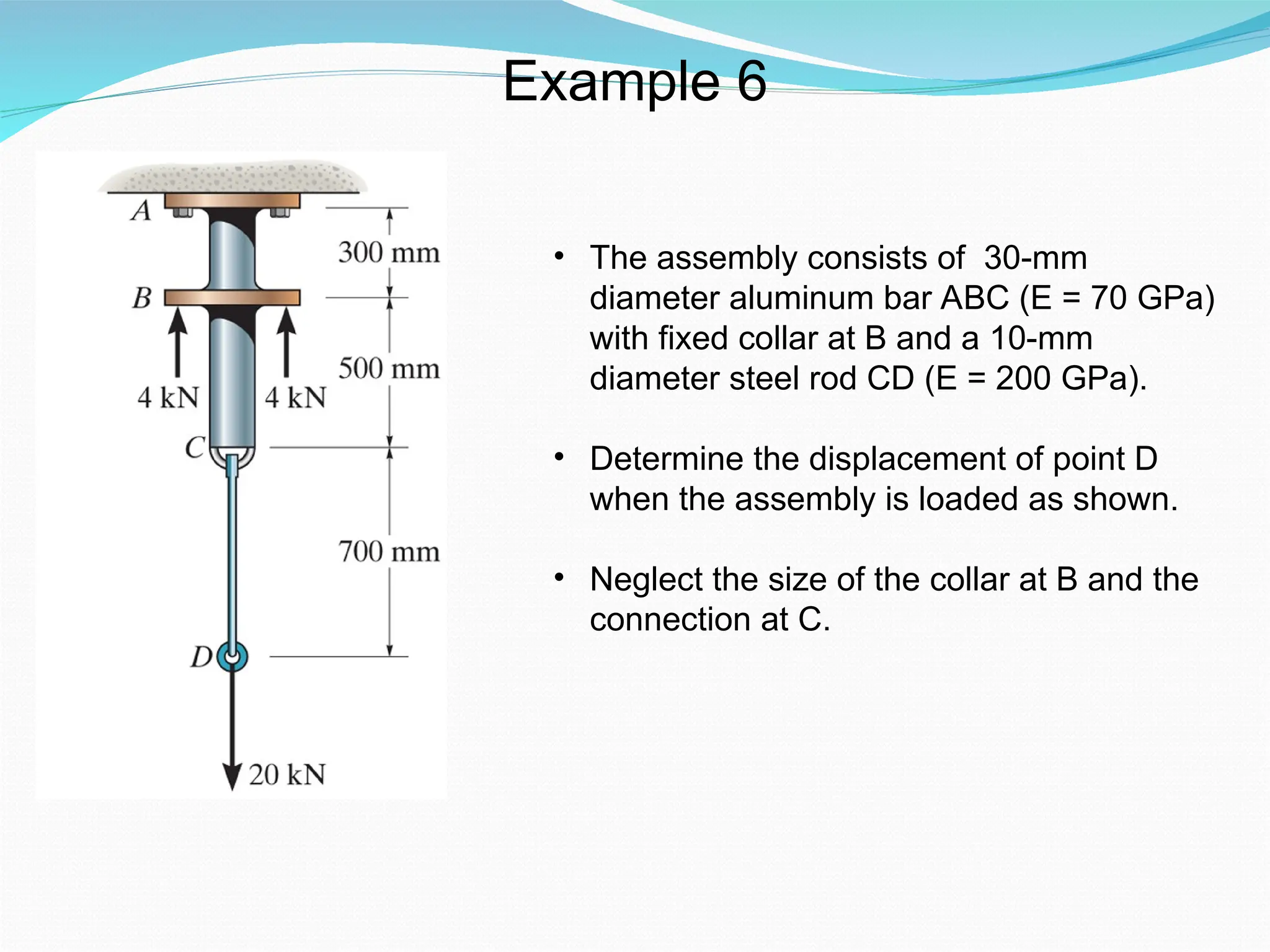
• The assemblyconsists of 30-mm
diameter aluminum bar ABC (E = 70 GPa)
with fixed collar at B and a 10-mm
diameter steel rod CD (E = 200 GPa).
• Determine the displacement of point D
when the assembly is loaded as shown.
• Neglect the size of the collar at B and the
connection at C.
Example 6
29.
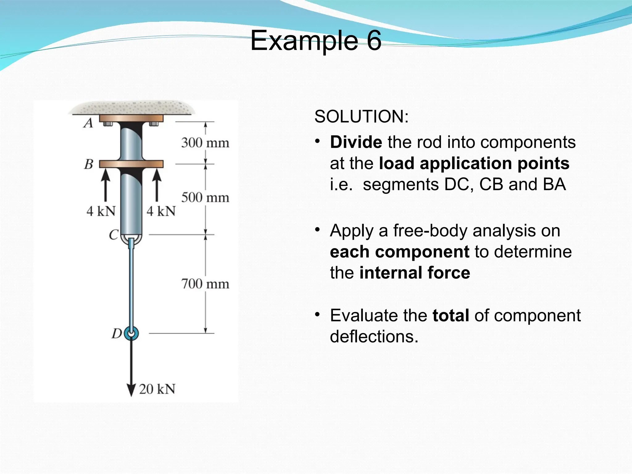
SOLUTION:
• Divide therod into components
at the load application points
i.e. segments DC, CB and BA
• Apply a free-body analysis on
each component to determine
the internal force
• Evaluate the total of component
deflections.
Example 6
30.
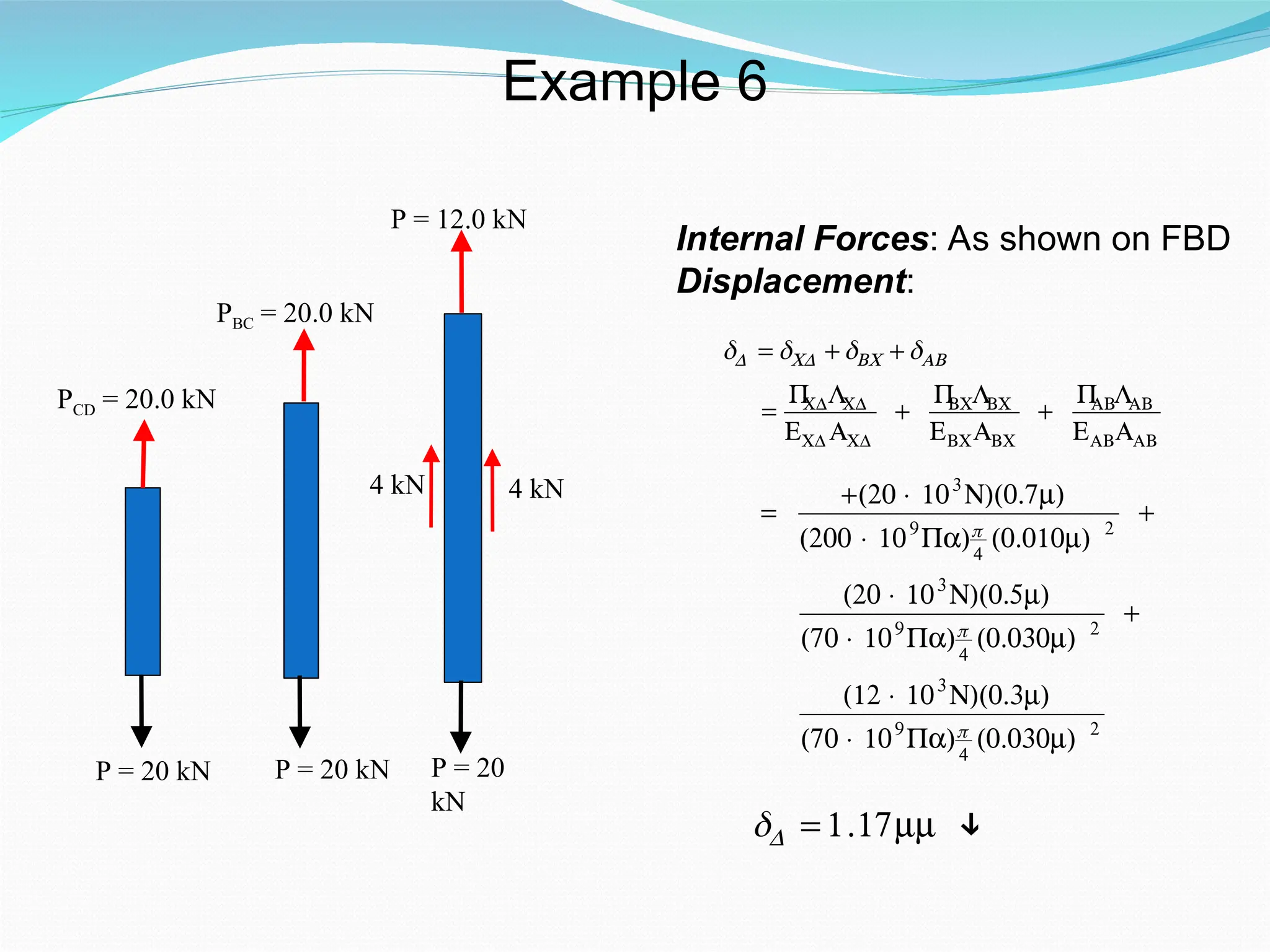
PCD = 20.0kN
P = 20 kN
PBC = 20.0 kN
P = 20 kN
Internal Forces: As shown on FBD
Displacement:
P = 12.0 kN
P = 20
kN
4 kN
4 kN
€
δD = δCD + δBC + δAB
=
P
CDLCD
ECD ACD
+
P
BCLBC
EBCABC
+
P
ABLAB
EABAAB
€
=
+(20 × 103
N)(0.7m)
(200 × 109
Pa)π
4
(0.010m) 2
+
(20 × 103
N)(0.5m)
(70 × 109
Pa)π
4
(0.030m) 2
+
(12 × 103
N)(0.3m)
(70 × 109
Pa)π
4
(0.030m) 2
δD = 1.17mm ↓
Example 6
31.
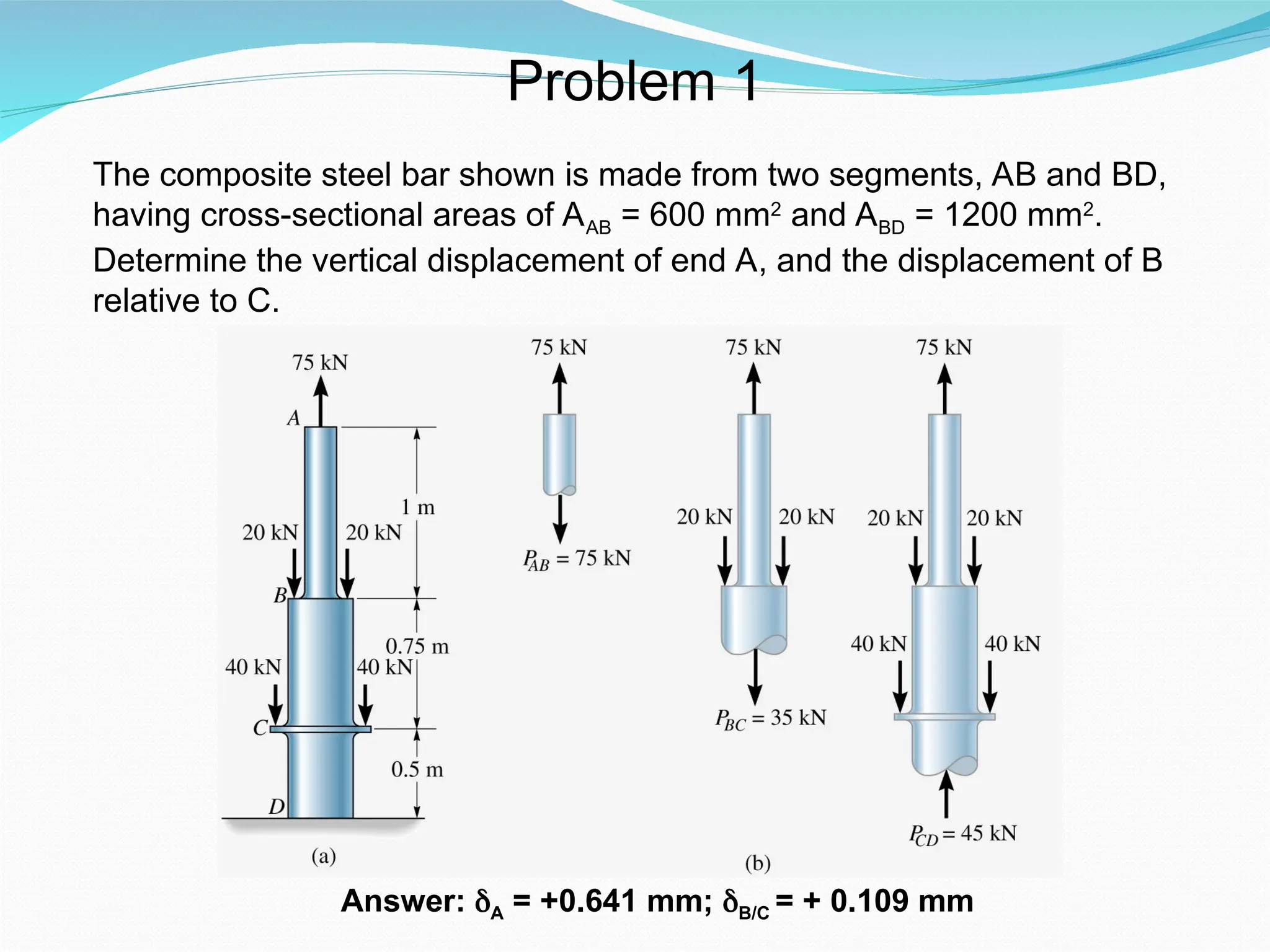
The composite steelbar shown is made from two segments, AB and BD,
having cross-sectional areas of AAB = 600 mm2
and ABD = 1200 mm2
.
Determine the vertical displacement of end A, and the displacement of B
relative to C.
Answer: δA = +0.641 mm; δB/C = + 0.109 mm
Problem 1
32.
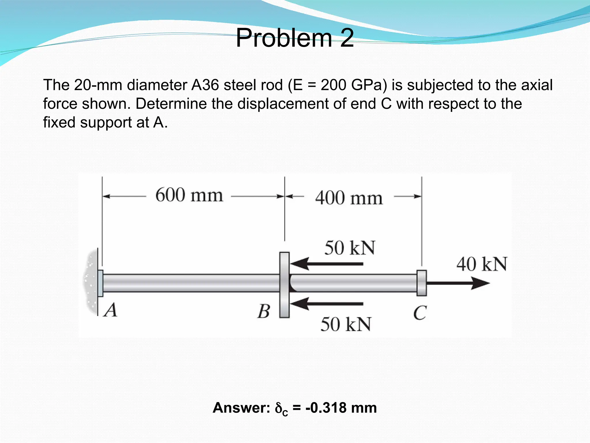
The 20-mm diameterA36 steel rod (E = 200 GPa) is subjected to the axial
force shown. Determine the displacement of end C with respect to the
fixed support at A.
Problem 2
Answer: δC = -0.318 mm
33.
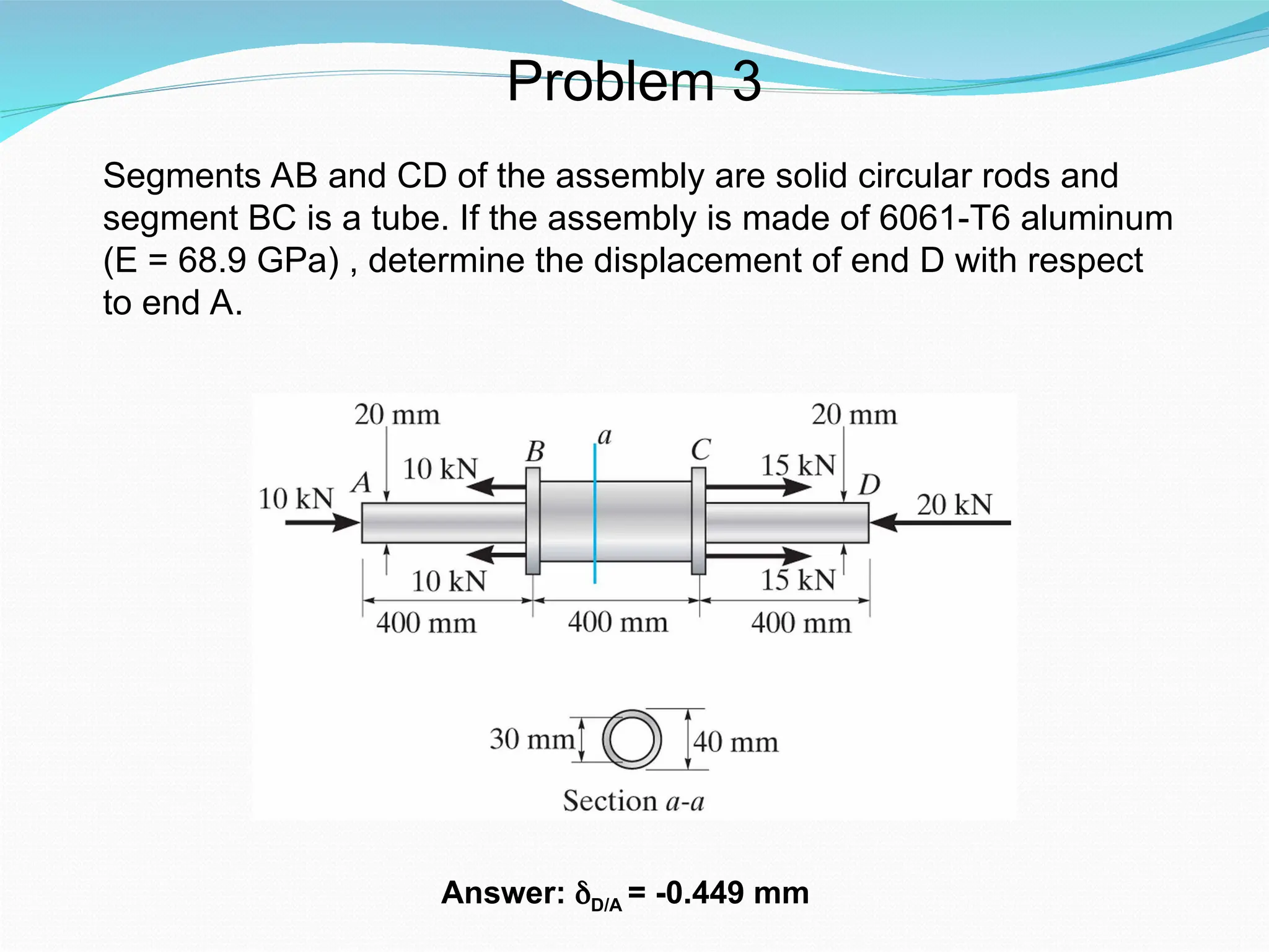
Segments AB andCD of the assembly are solid circular rods and
segment BC is a tube. If the assembly is made of 6061-T6 aluminum
(E = 68.9 GPa) , determine the displacement of end D with respect
to end A.
Problem 3
Answer: δD/A = -0.449 mm
34.
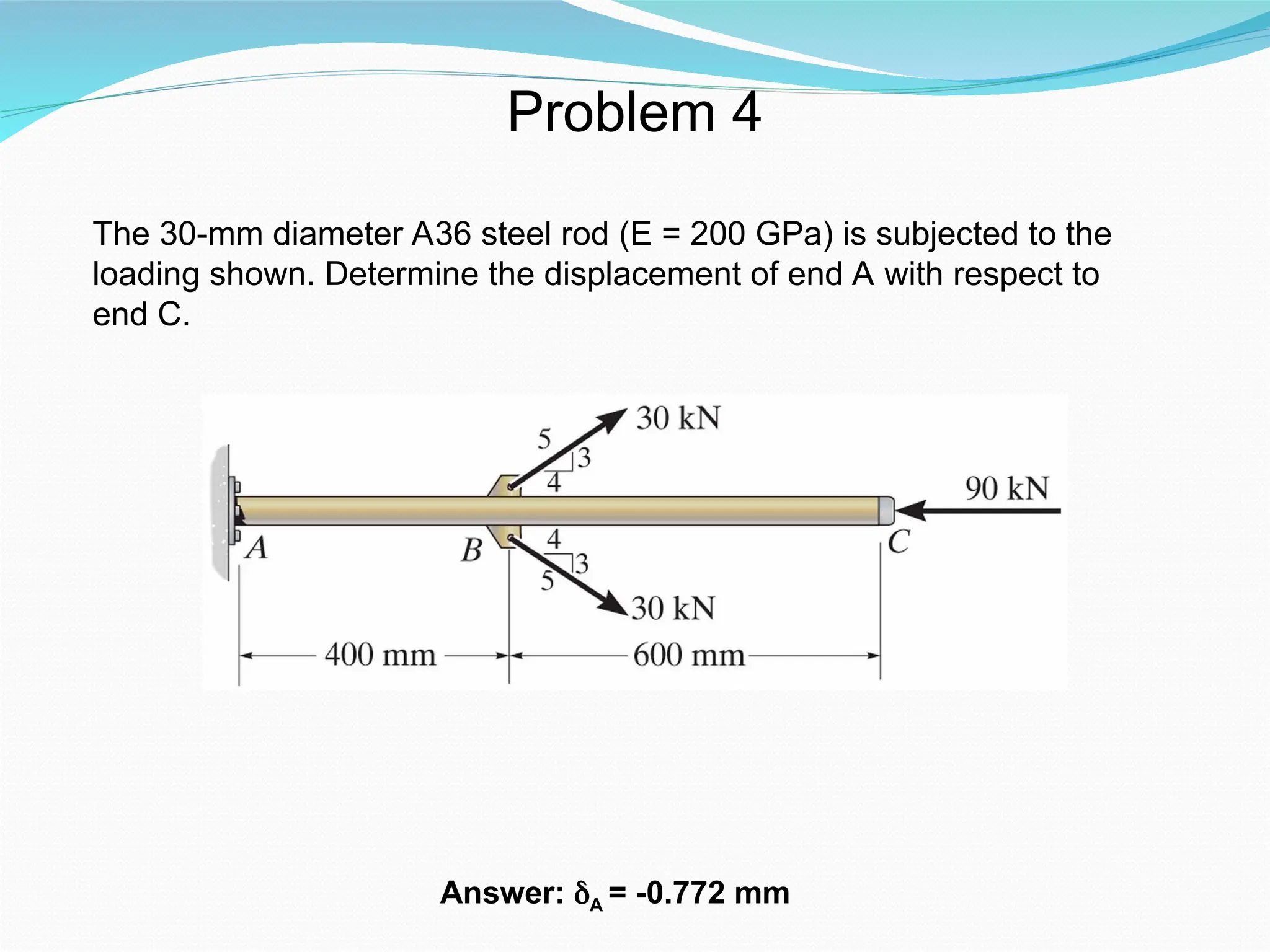
The 30-mm diameterA36 steel rod (E = 200 GPa) is subjected to the
loading shown. Determine the displacement of end A with respect to
end C.
Problem 4
Answer: δA = -0.772 mm
35.
Problem 5
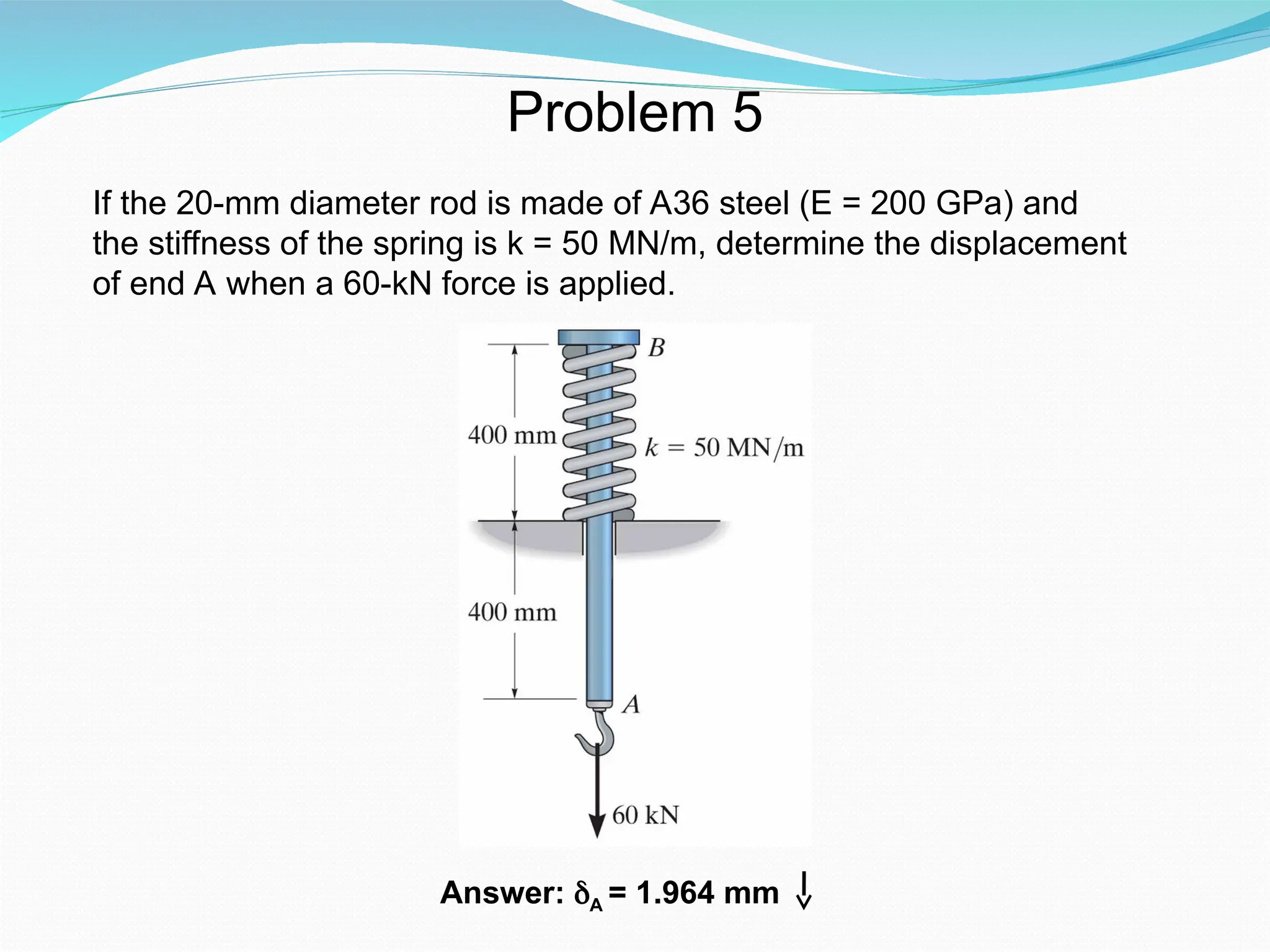
If the20-mm diameter rod is made of A36 steel (E = 200 GPa) and
the stiffness of the spring is k = 50 MN/m, determine the displacement
of end A when a 60-kN force is applied.
Answer: δA = 1.964 mm
36.
Problem 6
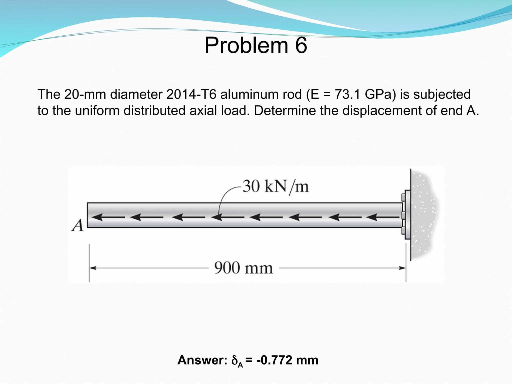
The 20-mmdiameter 2014-T6 aluminum rod (E = 73.1 GPa) is subjected
to the uniform distributed axial load. Determine the displacement of end A.
Answer: δA = -0.772 mm
37.
Problem 7
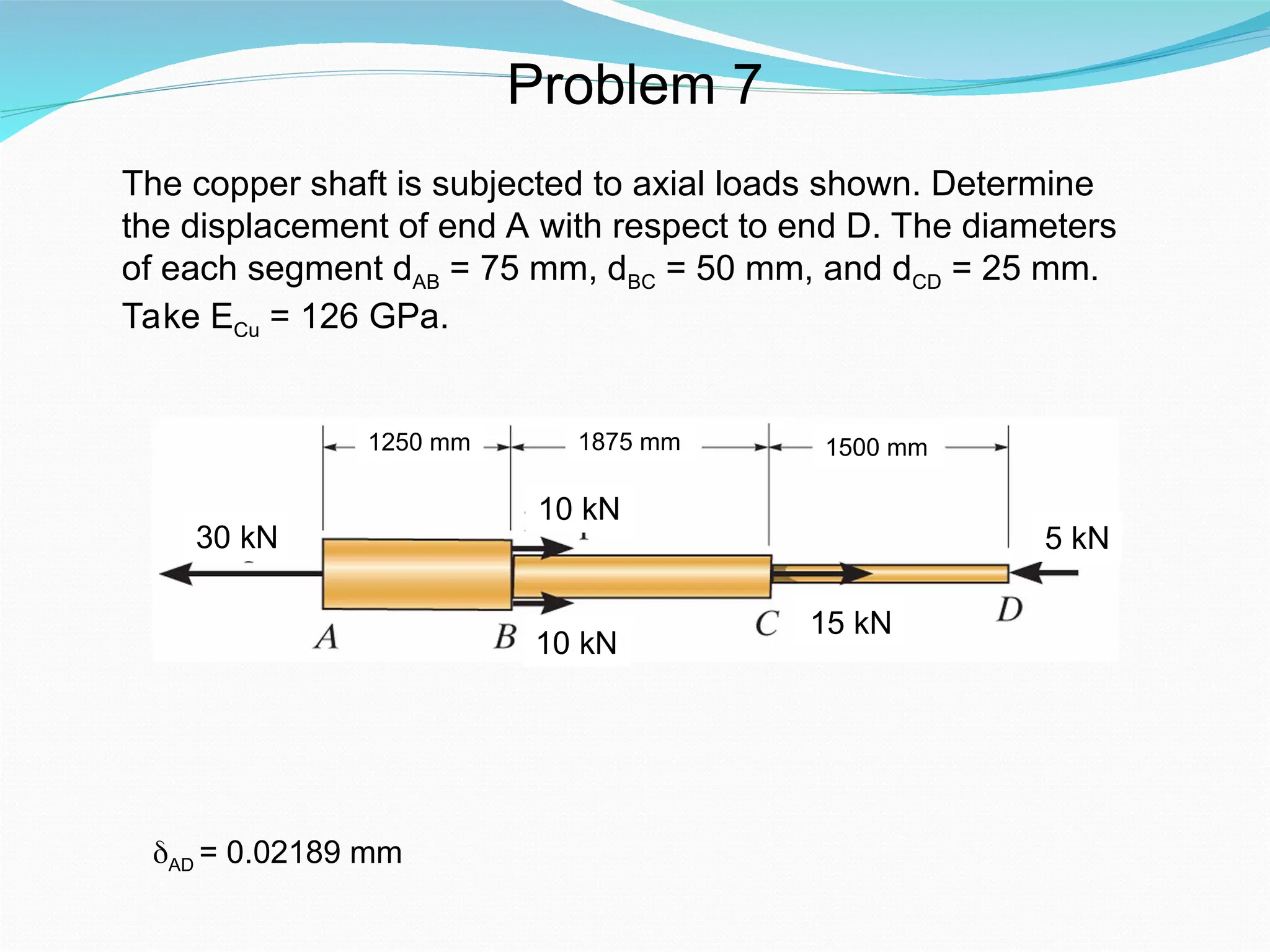
The coppershaft is subjected to axial loads shown. Determine
the displacement of end A with respect to end D. The diameters
of each segment dAB = 75 mm, dBC = 50 mm, and dCD = 25 mm.
Take ECu = 126 GPa.
30 kN
10 kN
1875 mm
10 kN
1250 mm 1500 mm
15 kN
5 kN
AD = 0.02189 mm
38.
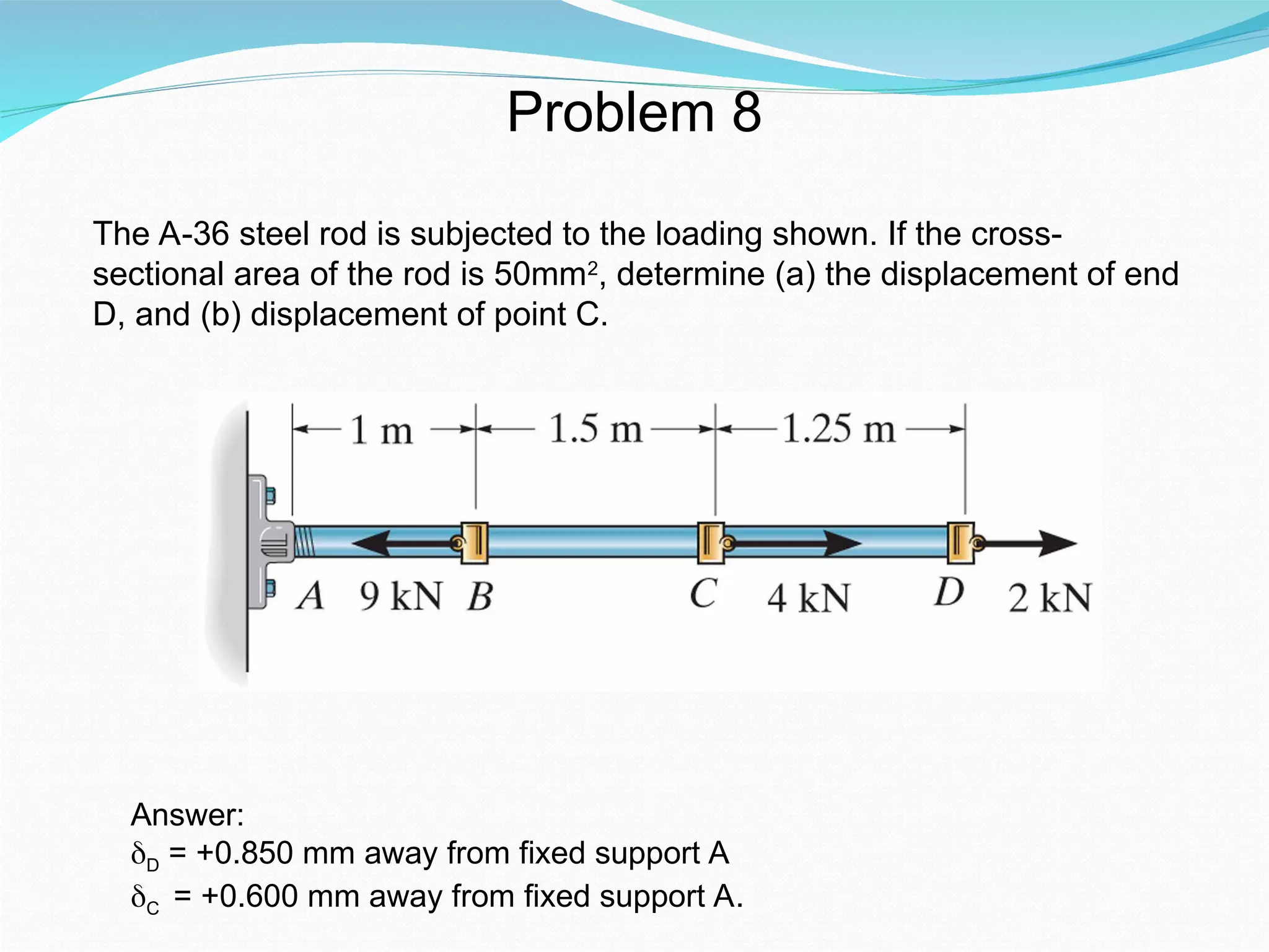
Problem 8
The A-36steel rod is subjected to the loading shown. If the cross-
sectional area of the rod is 50mm2
, determine (a) the displacement of end
D, and (b) displacement of point C.
Answer:
δD = +0.850 mm away from fixed support A
δC = +0.600 mm away from fixed support A.
39.
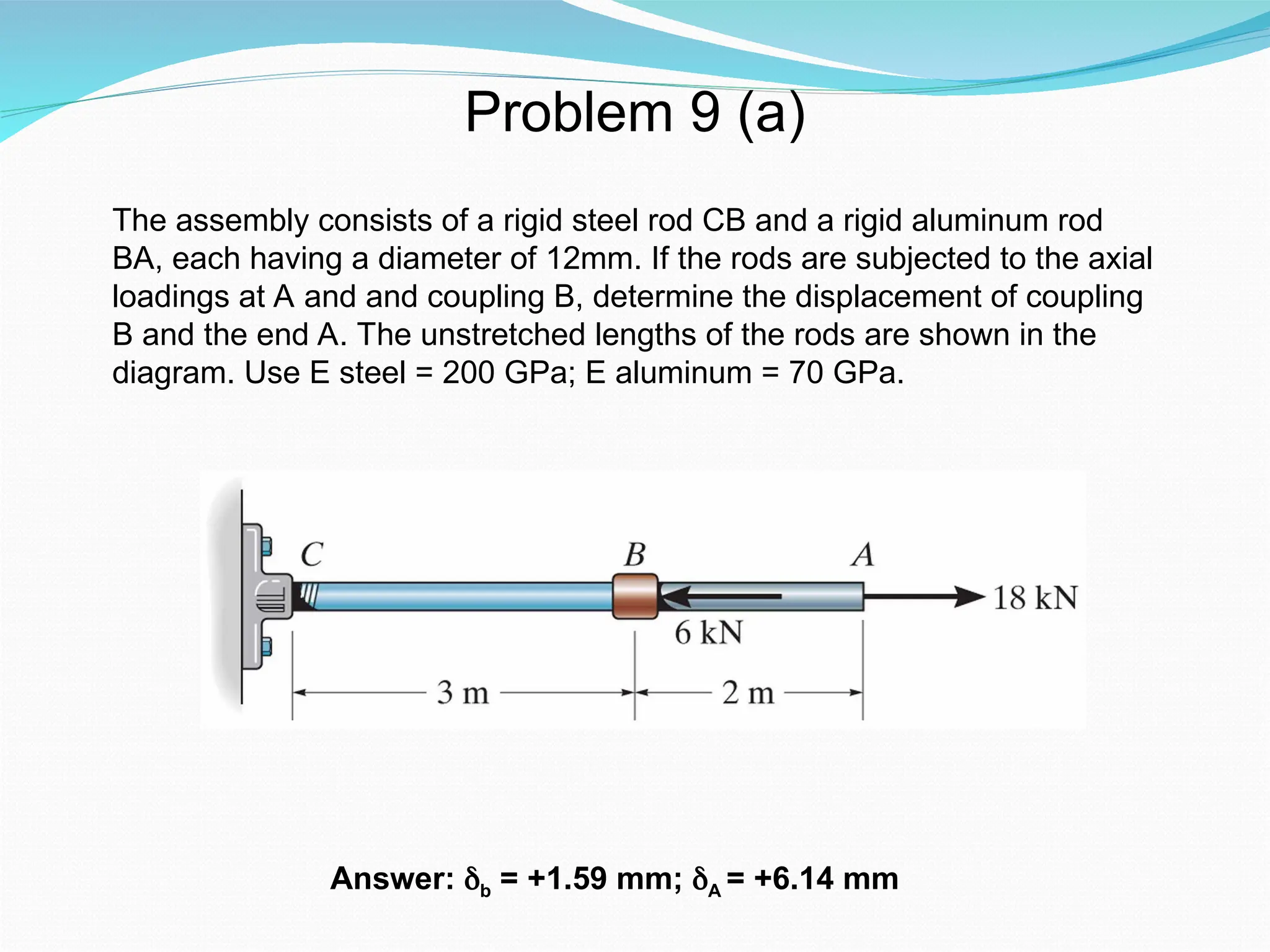
Problem 9 (a)
Answer:δb = +1.59 mm; δA = +6.14 mm
The assembly consists of a rigid steel rod CB and a rigid aluminum rod
BA, each having a diameter of 12mm. If the rods are subjected to the axial
loadings at A and and coupling B, determine the displacement of coupling
B and the end A. The unstretched lengths of the rods are shown in the
diagram. Use E steel = 200 GPa; E aluminum = 70 GPa.
40.
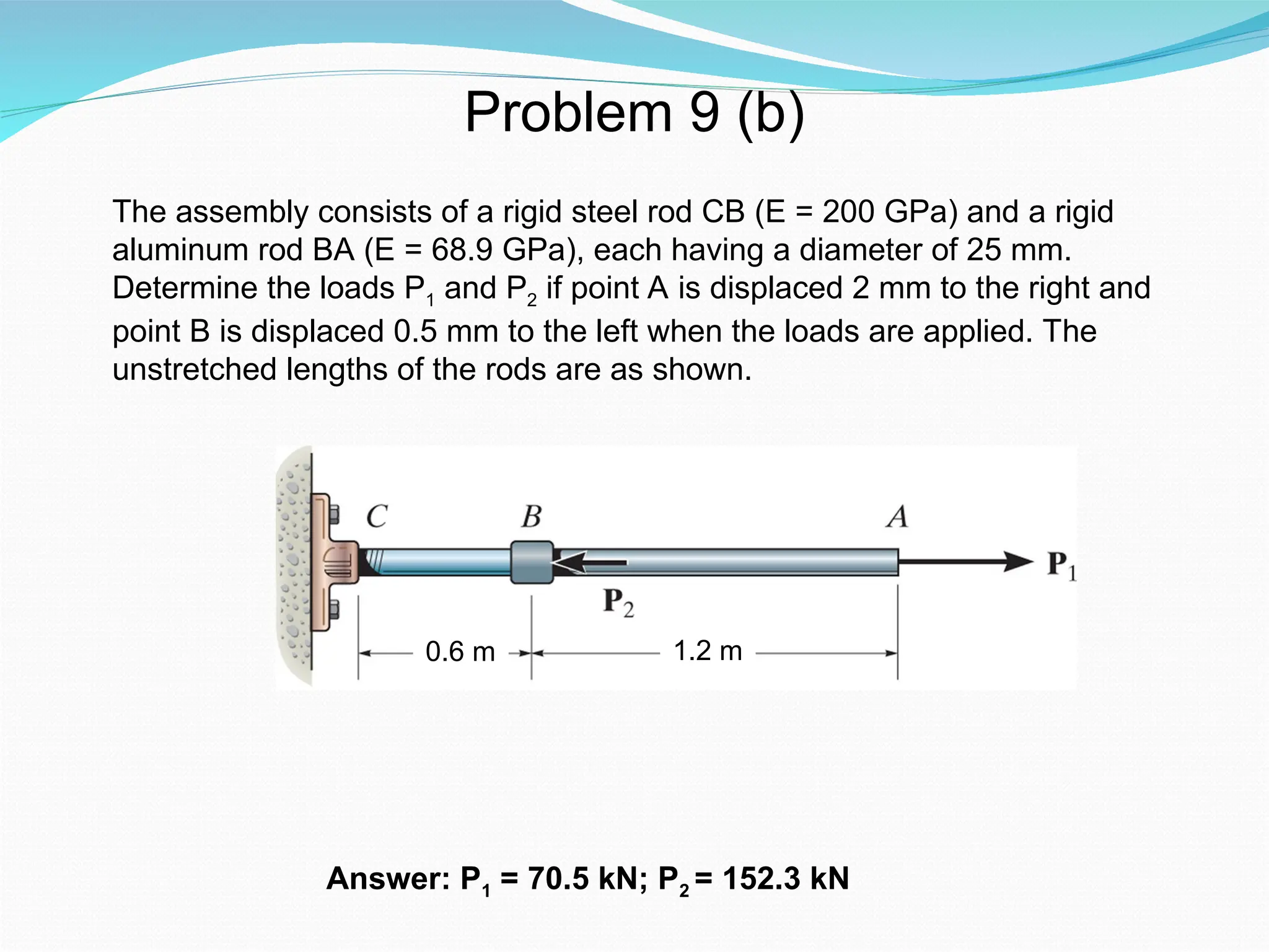
Problem 9 (b)
Answer:P1 = 70.5 kN; P2 = 152.3 kN
The assembly consists of a rigid steel rod CB (E = 200 GPa) and a rigid
aluminum rod BA (E = 68.9 GPa), each having a diameter of 25 mm.
Determine the loads P1 and P2 if point A is displaced 2 mm to the right and
point B is displaced 0.5 mm to the left when the loads are applied. The
unstretched lengths of the rods are as shown.
0.6 m 1.2 m
41.
1.35 m 4kN
1.5 m
1.2 m
0.3 m
0.6 m
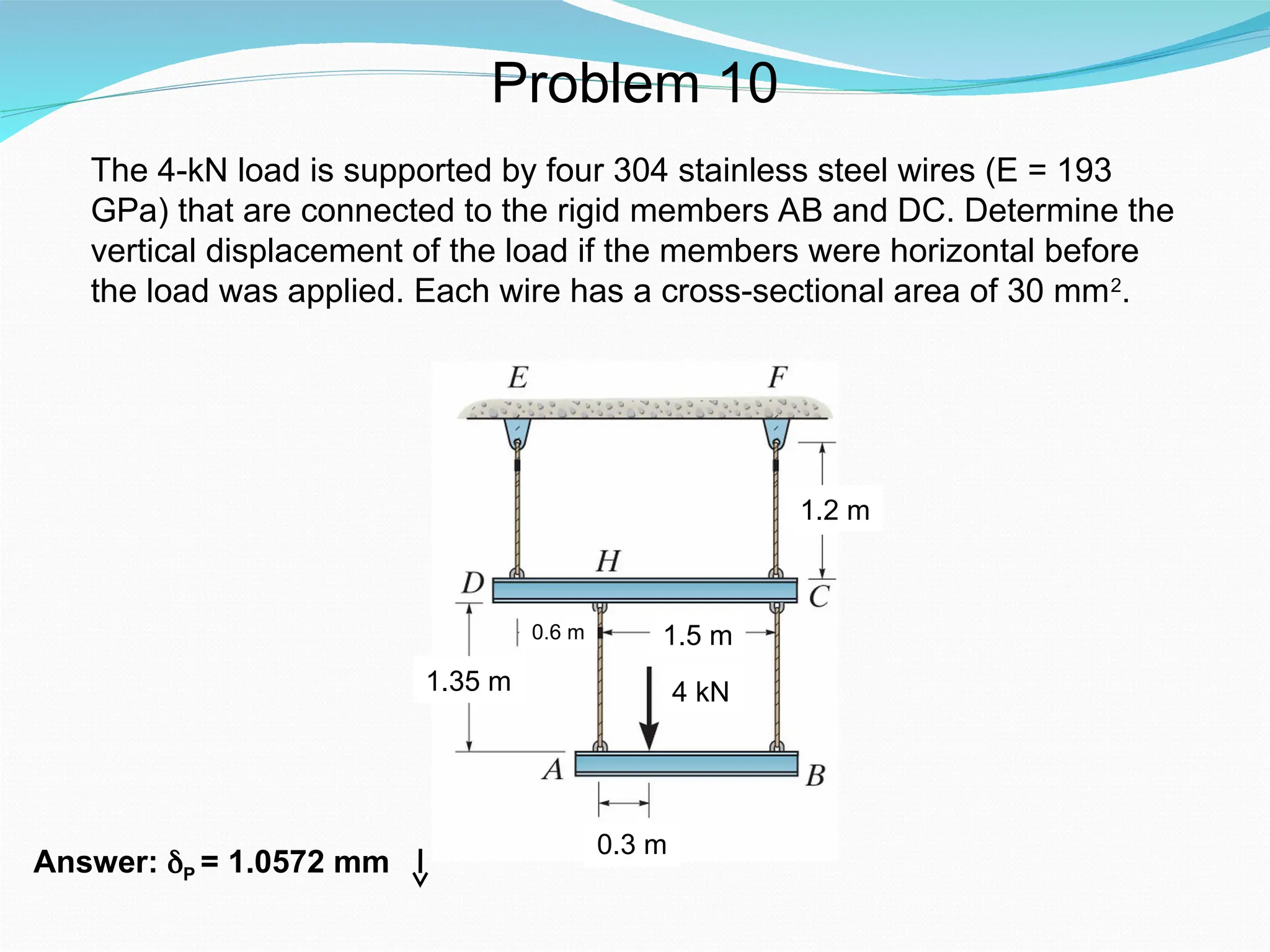
Problem 10
The 4-kN load is supported by four 304 stainless steel wires (E = 193
GPa) that are connected to the rigid members AB and DC. Determine the
vertical displacement of the load if the members were horizontal before
the load was applied. Each wire has a cross-sectional area of 30 mm2
.
Answer: δP = 1.0572 mm
42.
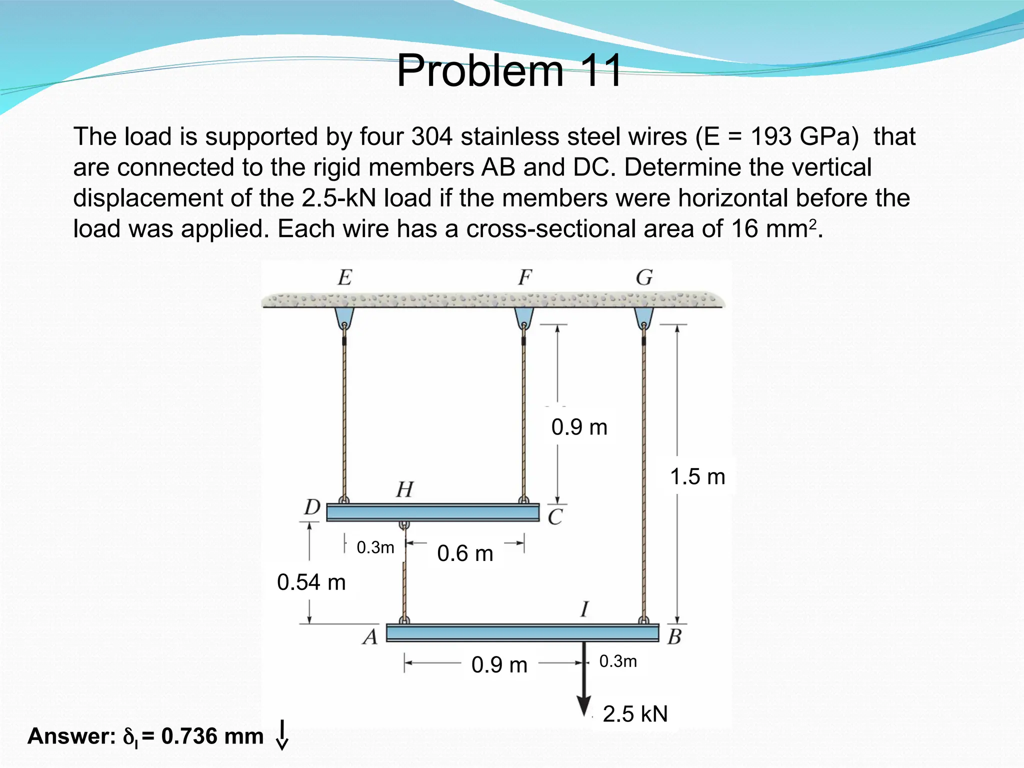
Problem 11
The loadis supported by four 304 stainless steel wires (E = 193 GPa) that
are connected to the rigid members AB and DC. Determine the vertical
displacement of the 2.5-kN load if the members were horizontal before the
load was applied. Each wire has a cross-sectional area of 16 mm2
.
0.54 m
0.6 m
0.9 m
0.9 m
1.5 m
Answer: δI = 0.736 mm
2.5 kN
0.3m
0.3m
43.
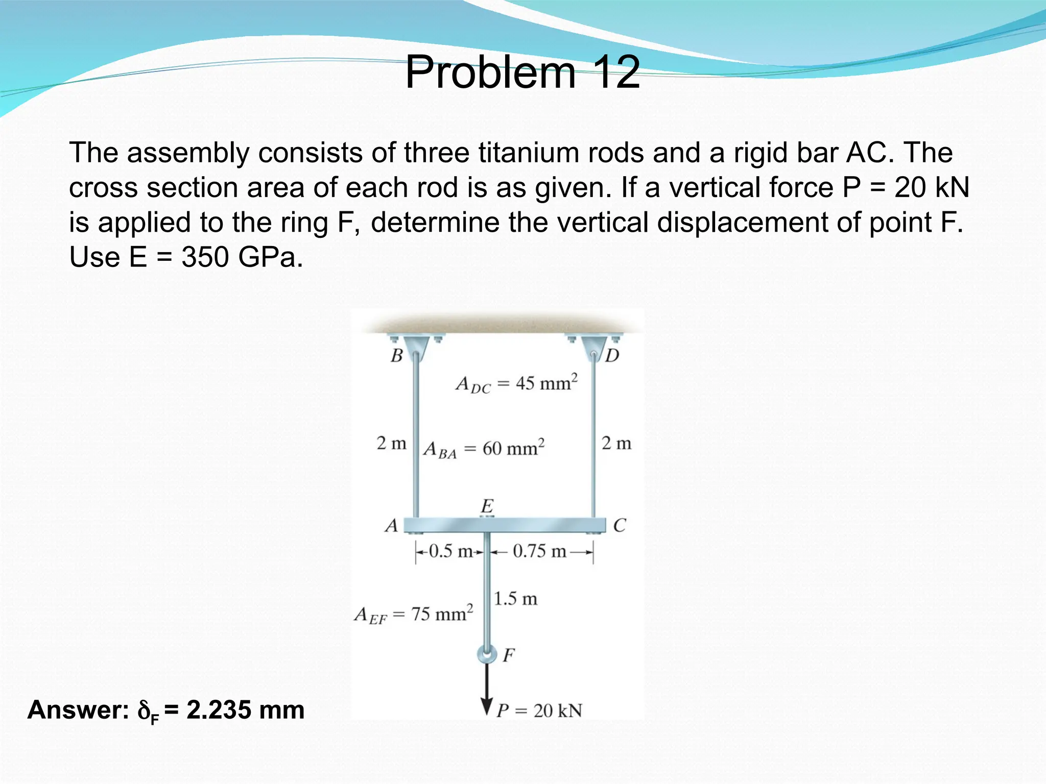
Problem 12
The assemblyconsists of three titanium rods and a rigid bar AC. The
cross section area of each rod is as given. If a vertical force P = 20 kN
is applied to the ring F, determine the vertical displacement of point F.
Use E = 350 GPa.
Answer: δF = 2.235 mm

![Example 2
Displacement of end A with respect to end D:
€
δA/D =
PL
EA
∑ =
(5 kN)(LAB)
AE
+
(−
3 kN)(LBC)
AE
+
(−
7 kN)(LCD )
AE
€
δA/D =
(1 m)
(200 × 109
N/m 2
)(1 m 2
)
5000 N + (−
3000 N) + (−
7000 N)
[ ]](https://image.slidesharecdn.com/ch2axialloadupdated-251109064745-90abe449/75/Chapter-2-Deformation-Under-Axial-Load-ppt-13-2048.jpg)