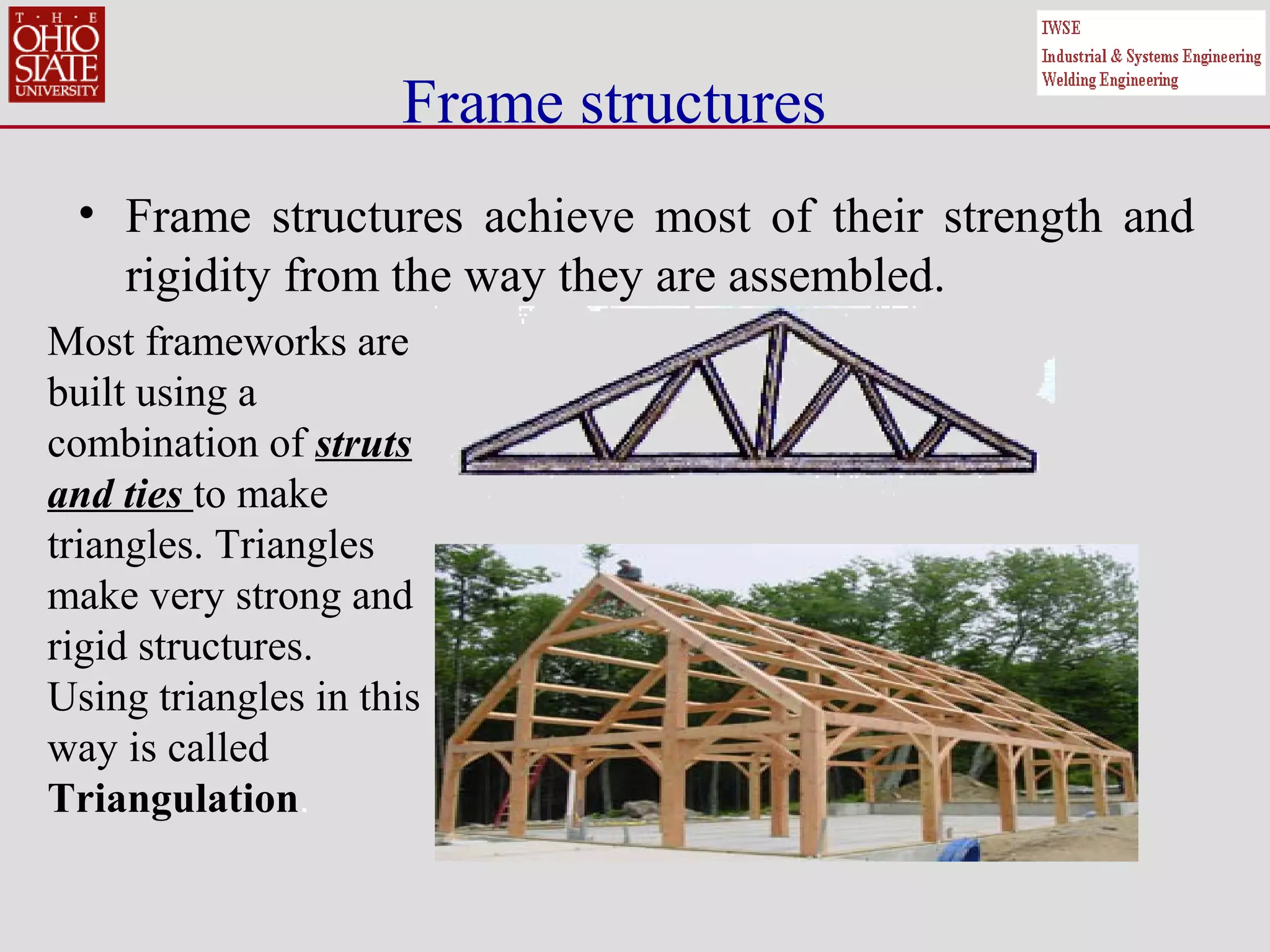
SlideShare a Scribd company logo
WHAT IS A
STRUCTURE?
A structure is something that
will support an object or a
load.
A structure must be strong enough to support its own weight
and whatever load is put on it !
There are three types of structure :
Mass Structures
Frame Structures
Shell structures.
Mass Structures are solid structures which rely
on their own weight to resist loads. A single
brick is a mass structure but so is a large dam.
Mass Structures
Frame Structures
Frame structures are made from many small parts (called
members (struts ties etc.)), joined together. Bridges, cranes and
parts of this oil rig are some examples.
Shell structures
•
Shell structures are made or assembled to make one piece. Tin
cans, bottles and other food containers are examples of shell
structures. Larger things such as car and aeroplane bodies are
examples of more complicated shell structures. Most shell
structures are made from thin sheet material (which makes
them light) and most have ridges or curves moulded into them
(to make them strong).
Natural Structures
•
Structures are not new, nature produced the first structures
long before humans were able to. A leaf is a natural structure.
Its veins provide support and carry nutrients. A tree has to
carry the weight of its own branches as well as resisting strong
winds.
Manufactured structures
• A manufactured structure is quite simply a structure
built by human beings.
Many of Nature's structures have been copied by
humans. The shell of a snail and the body of a
modern car are both shell structures designed to
protect their occupants.
Forces on Structures
• Force – push or pull that transfers energy to an object
• External force – come from outside, act upon the
structure. An external force is a force placed on the
structure from outside, by the wind perhaps or perhaps
by someone sitting or standing on it.
• Internal force – force that parts exert on each other,
act within structure. Internal forces are the forces
which the structure must provide within itself to resist
the external forces placed upon it. If the external forces
are greater than the internal forces, a structure will
collapse.
Forces acting on Structures
TYPES OF FORCES
Forces can be either static (stationary) or dynamic
(moving).
Static forces are
usually forces caused
by the weight of the
structure and anything
which is permanently
attached to it. Static
Load – changes
slowly or not at all,
eg: bricks in a
building, twigs in nest
Dynamic forces are caused
by things such as wind,
waves, people, and
vehicles. Dynamic forces
are usually much greater
than static forces and are
very difficult to predict.
These are the most
common reason for
structural failures.
Dynamic Load – move or
change, eg: car crossing
bridge, oil in pipeline
Forces can be internal or external
• 5 types of recognized forces:
compression, tension, torsion, shear & bending
• 1. Compression – shortens or crushes
• 2. Tension – stretches or pulls apart
• 3. Torsion – twists
• 4. Shear – pushes parts in opposite directions
• 5. Bending - stretches and squashes at the
same time.
Forces acting on and within Structures
External forces or loads cause internal stresses to be set up in a structure.
Not all forces or loads act in the same way. Forces can bend, pull, press,
or twist. Each of these types of force are given special names.
Tension : Is the name given to a force which tries to pull something apart. A structural
member in tension is called a tie. A Tie resists tensile stress. Tension forces stretch a
material by pulling its ends apart Tensile strength measures the largest tension force the
material can withstand before failing.
Compression : Is the name given to a force which tries to squash something together.
A structural member in compression is called a strut. A strut resists compressive stress..
Compression forces crush a material by squeezing it together. Compressive strength
measures the largest compression force the material can withstand before it loses its
shape or fails.
Internal Forces Within Structures
Compression, Tension, Torsion and Shear
•Shear : A shear force is created where two opposite forces try to cut tear
or rip something in two. Shear forces bend or tear a material by pressing
different parts in opposite directions at the same time. Shear strength
measures the largest shear force the material can withstand before it rips
apart.
•Torsion : Is the name given to a turning or a twisting force. Torsion
forces twist a material by turning the ends in opposite directions. Torsion
strength measures the largest torsion force the material can withstand
and still spring back into its original shape.
•Bending : Bending is a word you will have met before. A structure
which is subjected to bending is being stretched and squashed at the
same time.
THE EFFECT OF FORCES ON MATERIALS
• When a material is bent, stretched or compressed but returns to its
original size when the load is removed, we say it behaves in an elastic
way. Elastic bands are good examples.
• When a material is bent, stretched or compressed but does not return
to its original size when the load is removed we say it behaves in a
plastic way.
• Moist clay is a good example of a 'plastic' material.
A simple experiment with
a paper clip will show the
difference between elastic
and plastic behaviour. Up
to a certain point, a paper
clip will spring back into
shape when you bend the
end outwards and let go.
If you bend it too far,
it springs back slightly
but stays permanently
bent. When this
happens, it has been
bent beyond its elastic
Iimit. (see Hooke’s
law for springs)
MEMBERS IN A STRUCTURE
• The different parts of a frame structure are called members. Each
type of member has a different job to do in supporting the structure.
A Beam is a piece of material
supported at either end.
When a beam is loaded the
top is compressed and the
bottom is in tension.
They are usually
supported by
two or more
Columns.
Ideally beams
should be able
to span a wide
gap and support
a load without
deflecting.
Beams
• Beams used in larger structures take many different forms, some are
simply solid, some are hollow, and others have special cross-sections
to provide strength and rigidity.
A cantilever is a beam which is
supported at one end only.
Cantilevers are used where it is
not possible to have a support at
both ends (a diving board for
instance).
When a cantilever is loaded, the top surface is in
tension and the bottom is in compression.
Frame structures
• Frame structures achieve most of their strength and
rigidity from the way they are assembled.
Most frameworks are
built using a
combination of struts
and ties to make
triangles. Triangles
make very strong and
rigid structures.
Using triangles in this
way is called
Triangulation.
Shell structures
• Most shell structures achieve their strength and
rigidity from the way they are shaped. Shell
structures very rarely have large flat surfaces they
tend to be designed and made with ribs to act as
stiffeners.
Egg and light bulbs containers are
good examples. Both eggs and light
bulbs can withstand considerable
static forces if they are applied
carefully.
What they are not good at is resisting dynamic
forces.
This is why their containers are designed to
absorb impact.
Stress versus Strain
• Mechanical Properties
– Deal directly with behavior of materials under applied forces.
– Properties are described by applied stress and resulting strain, or applied
strain and resulting stress.
• Example: 100 lb force applied to the end of a rod results in a stress
applied to the end of the rod causing it to stretch or elongate, which is
measured as strain.
– Strength: ability of material to resist application of load without rupture.
• Ultimate strength- maximum force per cross section area.
• Yield strength- force at yield point per cross section area.
• Other strengths include rupture strength, proportional strength, etc.
– Stiffness: resistance of material to deform under load while in elastic
state.
• Stiffness is usually measured by the Modulus of Elasticity
(Stress/strain)
• Steel is stiff (tough to bend). Some beds are stiff, some are soft
(compliant)
21
Introduction
Mechanical properties that are important to a design
engineer differ from those that are of interest to the
manufacturing engineer.
• In design, mechanical properties such as elastic
modulus and yield strength are important in order to
resist permanent deformation under applied stresses.
Thus, the focus is on the elastic properties.
• In manufacturing, the goal is to apply stresses that
exceed the yield strength of the material so as to
deform it to the required shape. Thus, the focus is on
the plastic properties.
Testing Procedures
• Mechanical Testing
– Properties that deal with elastic or inelastic behavior of a
material under load
– Primary measurements involved are load applied and effects of
load application
– Two classification of tests; method of loading and the condition
of the specimen during the test
• Primary types of tests
– Tensile
– Compression
– Shear
– Torsion
– Flexure
Mechanical Test Considerations
• Principle factors are in three main areas
– manner in which the load is applied
– condition of material specimen at time of test
– surrounding conditions (environment) during testing
• Tests classification- load application
– kind of stress induced. Single load or Multiple loads
– rate at which stress is developed: static versus dynamic
– number of cycles of load application: single versus fatigue
• Primary types of loading
tension compression
shear
torsion
flexure shear
24
Tensile Test- Basic Principles
• The yield behavior of a material is
determined from the stress-strain
relationship under an applied state
of stress (tensile, compressive or
shear).
• An axial force applied to a specimen
of original length (lo) elongates it,
resulting in a reduction in the cross-
sectional area from Ao to A until
fracture occurs.
• The load and change in length
between two fixed points (gauge
length) is recorded and used to
determine the stress-strain
relationship.
• A similar procedure can be adopted
with a sheet specimen.
25
Basic Principles
• Step 1: Original shape and size
of the specimen with no load.
• Step 2: Specimen undergoing
uniform elongation.
• Step 3: Point of maximum load
and ultimate tensile strength.
• Step 4: The onset of necking
(plastic instability).
• Step 5: Specimen fractures.
• Step 6: Final length.
26
Terminology
Engineering Stress and Strain:
• These quantities are defined relative to the original
area and length of the specimen.
• The engineering stress (σe) at any point is defined as
the ratio of the instantaneous load or force (F) and the
original area (Ao).
• The engineering strain (e) is defined as the ratio of the
change in length (L-Lo) and the original length (Lo).
Stress
Stress = Measure of force felt by material
Force is measured in Newtons (N):
Area is measured using metres squared (m²)
Therefore answer will be Newton/metres squared, denoted using N/m2
1 N/m2
= 1 Pa(same as pressure). Pa is the SI unit short for Pascals
Stress =
Force
Area
Stress
• Stress: Intensity of the internally distributed forces or component of
forces that resist a change in the form of a body.
– Tension, Compression, Shear, Torsion, Flexure
• Stress calculated by force per unit area. Applied force divided by the
cross sectional area of the specimen.
• Stress units
– Pascals = Pa = Newtons/m2
– Pounds per square inch = Psi Note: 1MPa = 1 x10⁶
Pa = 145 psi
• Example
– Wire 12 in long is tied vertically. The wire has a diameter of 0.100
in and supports 100 lbs. What is the stress that is developed?
– Stress = F/A = F/πr2
= 100/(3.1415927 * 0.052
)= 12,739 psi =
87.86 MPa
A
F
=σ
29
The engineering stress is:
P is the load in lbs. Kgs. Etc. on the specimen and A0
is the
original cross-sectional area near the center of the specimen.
On the other hand, the true stress is the load divided by the true
area, which continues to be smaller by the tensile load.
The true stress continues to increase to the point of fracture,
while the engineering stress decreases to the point of fracture
due to the increasing load and the constant cross-sectional
area.
0
P
A
σ =
Stress
Example
•Tensile Bar is 10in x 1in x 0.1in is mounted vertically in
test machine. The bar supports 100 lbs. What is the stress
that is developed? What is the Load?
– Stress = F/A = F/(width*thickness) = 100lbs/
(1in*0.1in )=1,000 psi = 1000 psi/145psi = 6.897
Mpa
– Load = 100 lbs
•Block is 10 cm x 1 cm x 5 cm is mounted on its side in a
test machine. The block is pulled with 100 N on both
sides. What is the stress that is developed? What is the
Load?
– Stress = F/A = F/(width*thickness)= 100N/(.01m * .
10m )= 100,000 N/m2
= 100,000 Pa = 0.1 MPa= 0.1
MPa *145psi/MPa = 14.5 psi
– Load = 100 N
10cm
10in
1 in
0.1 in
1 cm
100 lbs
Strain
Strain = Measure of deformation F
A
∆L
L
Strain =
∆L
L
Strain
• Strain: Physical change in the dimensions of a specimen that results from
applying a load to the test specimen.
• Strain calculated by the ratio of the change in length and the original length.
(Deformation)
• Strain units (Dimensionless)
– When units are given they usually are in/in or mm/mm. (Change in dimension
divided by original length)
• % Elongation = strain x 100%
0l
l∆
=ε l0
lF
33
The engineering strain is:
0
0
l l
l
ε
−
=
l is the gage length at a given load and l0 is the
original gage length with zero load
Strain
Example
– Tensile Bar is 10in x 1in x 0.1in is mounted vertically
in test machine. The bar supports 100 lbs. What is the
strain that is developed if the bar grows to 10.2in?
What is % Elongation?
• Strain = (lf- l0)/l0 = (10.2 -10)/(10)= 0.02 in/in
• Percent Elongation = 0.02 * 100 = 2%
– Block is 10 cm x 1 cm x 5 cm is mounted on its side in
a test machine. The block is pulled with 1000 kN on
bone side. If the material elongation at yield is 1.5%,
how far will it grow at yield?
• Strain = Percent Elongation /100 = 1.5%/100 = 0.015 cm /cm
• Strain = (lf- l0)/l0 = (lf -5)/(5)= 0.015 cm/cm
• Growth = 5 * 0.015 = 0.075 cm
• Final Length = 5.075 cm
10cm 5
10in
1 in
0.1
1 c
100 lbs
Strain
• Permanent set is a change in form of a specimen once the
stress ends.
• Axial strain is the strain that occurs in the same direction
as the applied stress.
• Lateral strain is the strain that occurs perpendicular to the
direction of the applied stress.
• Poisson’s ratio is ratio of lateral strain to axial strain.
Poisson’s ratio = lateral strain
axial strain
– Example
• Calculate the Poisson’s ratio of a material with lateral strain of
0.002 and an axial strain of 0.006
• Poisson’s ratio = 0.002/0.006 = 0.333
Axial
Strain
Lateral
Strain
Note: For most materials, Poisson’s ratio is between 0.25 and 0.5
• Metals: 0.29 (304 SS) to 0.3 (1040 steel) to 0.35 (Mg)
•Ceramics and Glasses: 0.19 (TiC) to 0.26 (BeO) to 0.31 (Cordierite)
•Plastics: 0.35 (Acetals) to 0.41 (Nylons)
36
Stress strain diagrams
Stress-strain diagrams
plot stress against the
corresponding strain
produced.
Stress is the y-axis
Strain is the x-axis
Stress-Strain Curve
This stress-strain
curve is produced
from the tensile test.
37
Stress Strain for Different Materials
38
Modulus of Elasticity
• The slope of the stress-strain curve in the elastic
deformation region is the modulus of elasticity, is
known as Young's modulus
ε
σ
=E
Y =
F
A( )
∆L
L( )
Young’s Modulus (Tension)
F
A
∆L
L
•Measure of stiffness
• Tensile refers to tension
tensile stress
tensile strain
S =
F
A( )
∆x
h( )
Shear Modulus
Sheer Stress
Sheer Strain
41
Shear Testing - Introduction
•Shear testing involves an applied force or load that acts in a direction parallel to the
plane in which the load is applied. Shear loads act differently than, say, tensile or
compressive loads that act normal or perpendicular to the axis of loading. Direct shear
and torsional shear are important forces used to determine shear properties. Direct or
torsional loading depends on the forces a material is expected to be subjected to during
service.
Shear Testing - Procedure
•Before testing, the specimen is accurately measured using proper instruments and the
gage length is marked. The troptometer or a suitable replacement is attached to the
specimen and zeroed out. Proper precautions should be taken to center the specimen in
the machine or fixture. The grippers are tightened to insure against slippage, yet not so
tight as to cause deformations which would affect test results.
•In general, shear testing involves either direct or torsional loading. In direct shear
tests, the specimen is placed in the shear test fixture and a load is applied. This can be
seen in the figure below. For plate specimens, a punch and die combination may be
used. Plastics, generally, are square specimens with holes in either end to facilitate
gripping. The applied load and resultant deformation are recorded and a suitable graph
can be plotted.
42
B = −
∆F
A
∆V
V
= −
∆P
∆V
V( )
Bulk Modulus
Change in Pressure
Volume Strain
B = Y
3
44
Tensile Testing - Procedure
•Tensile tests are used to determine the tensile properties of a material, including the tensile
strength. The tensile strength of a material is the maximum tensile stress that can be developed in
the material.
•In order to conduct a tensile test, the proper specimen must be obtained. This specimen should
conform to ASTM standards for size and features. Prior to the test, the cross-sectional area may
be calculated and a pre-determined gage length marked.
•The specimen is then loaded into a machine set up for tensile loads and placed in the proper
grippers. Once loaded, the machine can then be used to apply a steady, continuous tensile load.
•Data is collected at pre-determined points or increments during the test. Depending on the
material and specimen being tested, data points may be more or less frequent. Data include the
applied load and change in gage length. The load is generally read from the machine panel in
pounds or kilograms.
45
•The change in gage length is determined using an extensometer. An extensometer is firmly fixed
to the machine or specimen and relates the amount of deformation or deflection over the gage
length during a test.
•While paying close attention to the readings, data points are collected until the material starts to
yield significantly. This can be seen when deformation continues without having to increase the
applied load. Once this begins, the extensometer is removed and loading continued until failure.
Ultimate tensile strength and rupture strength can be calculated from this latter loading.
•Once data have been collected, the tensile stress developed and the resultant strain can be
calculated. Stress is calculated based on the applied load and cross-sectional area. Strain is the
change in length divided by the original length.
46
Tensile Test
Tensile testing machine:
Load indicator
Clamps to hold
the specimen
Unload Lever
Load Lever
Machine dial
Load indicator
Clamps to hold
the specimen
Unload Lever
Load Lever
Load indicator
Clamps to hold
the specimen
Unload Lever
Load Lever
Machine dial
47
Tensile Test
Test Specimen: • The tensile test can be conducted
with either a round bar or sheet
specimen.
• The round bar specimen used for
the current test complies with the
ASTM standards.
• A 2 inch gage length is marked on
the specimen prior to testing.
• The specimen is held in the clamps
at either end. Load and movement
are applied to the bottom clamp.
Gauge
markings
Gauge
markings
48
Comparison of final lengths (total elongation) of specimens
at fracture with different n values using FE simulations
Fracture occurs after a certain amount of elongation that is
influenced by the n-value
(a) n=0.2 (b) n =0.4 (c) n = 0.6
Simulation results- Fracture
49
Compression Testing - Introduction
•Simplistically, compression testing is the opposite of tensile testing. A compressive
load tends to squeeze or compact the specimen. The choice of a compression test over
other types of testing largely depends on the type of loading the material will see during
application or service.
•Metals and many plastics, for example, are more efficient at resisting tensile loads.
Therefore, they are more commonly tested using tensile loading, depending on the
application, of course. Materials, such as concrete, brick, and some ceramic products,
are more often used in applications for their compressive loading properties and are,
therefore, tested in compression. Again, it is important to choose the test that best
reflects the loads and conditions the material will be subjected to in application or
service.
50
Compression Testing – Procedure
During a typical compression test, data are collected
regarding the applied load, resultant deformation or
deflection, and condition of the specimen. For brittle
materials, the compressive strength is relatively easy to
obtain, showing marked failure. However, for ductile
materials, the compressive strength is generally based on an
arbitrary deformation value. Ductile materials do not exhibit
the sudden fractures that brittle materials present. They tend
to buckle and "barrel out".
51
Barreling or Bulging of a Sample under
Compressive Loads
52
•Prior to this and any test, the dimensions of the specimen should be
measured with adequate precision using proper instruments. Once
these measurements have been taken and recorded, the specimen
should be loaded into the testing machine.
•In compression testing, and testing in general, care should be taken
to insure that the axis of the specimen is centered and aligned with
the axis of loading.
•Loading rates should be steady and continuous. Rates vary, but a
general figure is 0.005 inches per minute strain rate. Loading rates
typically range from 500-1000 lb/min.
53
Factor of safety (FoS), also known as (and used
interchangeably with) safety factor (SF), is a term
describing the structural capacity of a system
beyond the expected loads or actual loads.
Essentially, how much stronger the system is than it
usually needs to be for an intended load. Safety
factors are often calculated using detailed analysis
because comprehensive testing is impractical on many
projects, such as bridges and buildings, but the
structure's ability to carry load must be determined
to a reasonable accuracy.
Many systems are purposefully built much stronger
than needed for normal usage to allow for emergency
situations, unexpected loads, misuse, or degradation
54
Calculation
There are several ways to compare the factor of safety for structures. All
the different calculations fundamentally measure the same thing: how much
extra load beyond what is intended a structure will actually take (or be
required to withstand). The difference between the methods is the way in
which the values are calculated and compared. Safety factor values can be
thought of as a standardized way for comparing strength and reliability
between systems.
The use of a factor of safety does not imply that an item, structure, or
design is "safe". Many quality assurance, engineering design, manufacturing,
installation, and end-use factors may influence whether or not something is
safe in any particular situation.
                                       
EXAMPLE CALCULATION
1) The tensile (material) strength of a specific metal bar is
766N/mm². the maximum permissible stress (design load) is
456N/mm². calculate the FoS.
•FoS = 766N/mm² = 1.68
456N/mm²
2) A column of pre-stressed concrete will be subjected to various
loads and as such is required to have a permissible stress (design
load) of 23N/mm², with a FoS of 3. Calculate the compressive
stress (material strength) of the concrete.
•FoS (3) = compressive stress
23N/mm²
•Hence compressive stress = 3 x 23N/mm² = 69N/mm²
3) Steel rebars are required to have a material strength of
524N/mm², with a FoS of 3. Calculate the design load for the steel.
•FoS (3) = 524N/mm²
design load

More Related Content

What's hot

Methods of rcc design
Methods of rcc designMethods of rcc design
Methods of rcc design
Selvakumar Palanisamy
 
Stress,strain,load
Stress,strain,loadStress,strain,load
Stress,strain,load
kinjal2112
 
Analysis of Truss
Analysis of TrussAnalysis of Truss
Analysis of Truss
DHA Suffa University
 
Shear force and bending moment
Shear force and bending moment Shear force and bending moment
Shear force and bending moment
temoor abbasa
 
presentation based on Truss and Frame
presentation based on Truss and Framepresentation based on Truss and Frame
presentation based on Truss and FrameMohotasimur Anik
 
Buckling of Columns
 Buckling of Columns Buckling of Columns
Buckling of Columns
Dr. Bhimsen Soragaon
 
Compression member
Compression memberCompression member
Compression member
Divya Vishnoi
 
Design of steel structures Introduction
Design of steel structures IntroductionDesign of steel structures Introduction
Design of steel structures Introduction
Prakash Kumar Sekar
 
Introduction of Reinforced Concrete Design
Introduction of Reinforced Concrete DesignIntroduction of Reinforced Concrete Design
Introduction of Reinforced Concrete Design
maylene san luis
 
Beam and its types
Beam and its typesBeam and its types
Beam and its types
Yuga Aravind Kumar
 
Types of support
Types of supportTypes of support
Types of support
milanpatel007
 
Design of purlins
Design of purlinsDesign of purlins
Design of purlinsbeqs
 
Seismic retrofitting techniques & rehabilitation
Seismic retrofitting techniques & rehabilitationSeismic retrofitting techniques & rehabilitation
Seismic retrofitting techniques & rehabilitation
Shuvam Sarkar
 
Lec 2 stress strain diagram (lec 2)
Lec 2 stress strain diagram (lec 2)Lec 2 stress strain diagram (lec 2)
Lec 2 stress strain diagram (lec 2)
Abdul Rehman Memon
 
Shear wall and its design guidelines
Shear wall and its design guidelinesShear wall and its design guidelines
Shear wall and its design guidelines
Muhammad Zain Ul abdin
 
Types of beam
Types of beamTypes of beam
Types of beam
Engr Ajeet kumar
 
Classification of Loads on Structures
Classification of Loads on StructuresClassification of Loads on Structures
Classification of Loads on Structures
zameer1979
 
mechanics of solids
mechanics of solidsmechanics of solids
mechanics of solids
jayrishabh
 
Structural System Overview
Structural System OverviewStructural System Overview
Structural System OverviewAmjed Bin-Ali
 

What's hot (20)

Methods of rcc design
Methods of rcc designMethods of rcc design
Methods of rcc design
 
Stress,strain,load
Stress,strain,loadStress,strain,load
Stress,strain,load
 
Analysis of Truss
Analysis of TrussAnalysis of Truss
Analysis of Truss
 
Shear force and bending moment
Shear force and bending moment Shear force and bending moment
Shear force and bending moment
 
presentation based on Truss and Frame
presentation based on Truss and Framepresentation based on Truss and Frame
presentation based on Truss and Frame
 
Buckling of Columns
 Buckling of Columns Buckling of Columns
Buckling of Columns
 
Compression member
Compression memberCompression member
Compression member
 
Design of steel structures Introduction
Design of steel structures IntroductionDesign of steel structures Introduction
Design of steel structures Introduction
 
Introduction of Reinforced Concrete Design
Introduction of Reinforced Concrete DesignIntroduction of Reinforced Concrete Design
Introduction of Reinforced Concrete Design
 
Beam and its types
Beam and its typesBeam and its types
Beam and its types
 
Types of support
Types of supportTypes of support
Types of support
 
Design of purlins
Design of purlinsDesign of purlins
Design of purlins
 
Seismic retrofitting techniques & rehabilitation
Seismic retrofitting techniques & rehabilitationSeismic retrofitting techniques & rehabilitation
Seismic retrofitting techniques & rehabilitation
 
Lec 2 stress strain diagram (lec 2)
Lec 2 stress strain diagram (lec 2)Lec 2 stress strain diagram (lec 2)
Lec 2 stress strain diagram (lec 2)
 
Introduction to Engineering Mechanics
Introduction to Engineering MechanicsIntroduction to Engineering Mechanics
Introduction to Engineering Mechanics
 
Shear wall and its design guidelines
Shear wall and its design guidelinesShear wall and its design guidelines
Shear wall and its design guidelines
 
Types of beam
Types of beamTypes of beam
Types of beam
 
Classification of Loads on Structures
Classification of Loads on StructuresClassification of Loads on Structures
Classification of Loads on Structures
 
mechanics of solids
mechanics of solidsmechanics of solids
mechanics of solids
 
Structural System Overview
Structural System OverviewStructural System Overview
Structural System Overview
 

Similar to 2a. structures, compression, torsion, shear, bending, tension, stress & strain, fo s good ppt

Mechanics of Solids Fundamentals.pdf
Mechanics of Solids Fundamentals.pdfMechanics of Solids Fundamentals.pdf
Mechanics of Solids Fundamentals.pdf
Bharti Shinde
 
Structures presentation for 3rd ESO
Structures presentation for 3rd ESOStructures presentation for 3rd ESO
Structures presentation for 3rd ESO
gabriela-technoteacher
 
Mechanical Properties of Dental Materials
Mechanical Properties of Dental MaterialsMechanical Properties of Dental Materials
Mechanical Properties of Dental Materials
Hemavathi N
 
Mechanical properties of dental materials
Mechanical properties of dental materialsMechanical properties of dental materials
Mechanical properties of dental materials
alka shukla
 
Properties of materials
Properties of materialsProperties of materials
Properties of materials
Dhrubajyoti Ray
 
Unit 5_S1-S2 Mechanical Properties of Solids.pptx
Unit 5_S1-S2 Mechanical Properties of Solids.pptxUnit 5_S1-S2 Mechanical Properties of Solids.pptx
Unit 5_S1-S2 Mechanical Properties of Solids.pptx
AdittyaSenGupta
 
biomechanics-150911072531-lva1-app6892.pdf
biomechanics-150911072531-lva1-app6892.pdfbiomechanics-150911072531-lva1-app6892.pdf
biomechanics-150911072531-lva1-app6892.pdf
RidzwanSafai1
 
Biomechanics
Biomechanics Biomechanics
Biomechanics
anamohammedalhussein
 
Mech props
Mech propsMech props
Mech props
AKASH SAHA
 
Engineering Materials.pptx
Engineering Materials.pptxEngineering Materials.pptx
Engineering Materials.pptx
Partap Samra
 
Lecture07 Types & Processes A Sr
Lecture07 Types & Processes A SrLecture07 Types & Processes A Sr
Lecture07 Types & Processes A SrGalala University
 
Introduction to Elasticity of materials
Introduction to Elasticity of materialsIntroduction to Elasticity of materials
Introduction to Elasticity of materials
Praveen Vaidya
 
General properties of connective tissues.pptx
General properties of connective tissues.pptxGeneral properties of connective tissues.pptx
General properties of connective tissues.pptx
Anand Patel
 
Basics of strength of materials
Basics of strength of materialsBasics of strength of materials
Basics of strength of materials
Yuga Aravind Kumar
 
General properties of connective tissues.pptx
General properties of connective tissues.pptxGeneral properties of connective tissues.pptx
General properties of connective tissues.pptx
Anand Patel
 
1.3_Strength properties.pptx
1.3_Strength properties.pptx1.3_Strength properties.pptx
1.3_Strength properties.pptx
MalithMadushan1
 
Elements of Solid Mechanics.ppt
Elements of  Solid Mechanics.pptElements of  Solid Mechanics.ppt
Elements of Solid Mechanics.ppt
Sadia Textile
 
Properties of matter - Elasticity
Properties of matter - ElasticityProperties of matter - Elasticity
Properties of matter - Elasticity
amalajanet
 

Similar to 2a. structures, compression, torsion, shear, bending, tension, stress & strain, fo s good ppt (20)

Mechanics of Solids Fundamentals.pdf
Mechanics of Solids Fundamentals.pdfMechanics of Solids Fundamentals.pdf
Mechanics of Solids Fundamentals.pdf
 
Structures presentation for 3rd ESO
Structures presentation for 3rd ESOStructures presentation for 3rd ESO
Structures presentation for 3rd ESO
 
Mechanical Properties of Dental Materials
Mechanical Properties of Dental MaterialsMechanical Properties of Dental Materials
Mechanical Properties of Dental Materials
 
Mechanical properties of dental materials
Mechanical properties of dental materialsMechanical properties of dental materials
Mechanical properties of dental materials
 
Properties of materials
Properties of materialsProperties of materials
Properties of materials
 
Unit 5_S1-S2 Mechanical Properties of Solids.pptx
Unit 5_S1-S2 Mechanical Properties of Solids.pptxUnit 5_S1-S2 Mechanical Properties of Solids.pptx
Unit 5_S1-S2 Mechanical Properties of Solids.pptx
 
biomechanics-150911072531-lva1-app6892.pdf
biomechanics-150911072531-lva1-app6892.pdfbiomechanics-150911072531-lva1-app6892.pdf
biomechanics-150911072531-lva1-app6892.pdf
 
Biomechanics
Biomechanics Biomechanics
Biomechanics
 
Forces
ForcesForces
Forces
 
Mech props
Mech propsMech props
Mech props
 
Engineering Materials.pptx
Engineering Materials.pptxEngineering Materials.pptx
Engineering Materials.pptx
 
Lecture07 Types & Processes A Sr
Lecture07 Types & Processes A SrLecture07 Types & Processes A Sr
Lecture07 Types & Processes A Sr
 
Introduction to Elasticity of materials
Introduction to Elasticity of materialsIntroduction to Elasticity of materials
Introduction to Elasticity of materials
 
General properties of connective tissues.pptx
General properties of connective tissues.pptxGeneral properties of connective tissues.pptx
General properties of connective tissues.pptx
 
Basics of strength of materials
Basics of strength of materialsBasics of strength of materials
Basics of strength of materials
 
General properties of connective tissues.pptx
General properties of connective tissues.pptxGeneral properties of connective tissues.pptx
General properties of connective tissues.pptx
 
Technolo
TechnoloTechnolo
Technolo
 
1.3_Strength properties.pptx
1.3_Strength properties.pptx1.3_Strength properties.pptx
1.3_Strength properties.pptx
 
Elements of Solid Mechanics.ppt
Elements of  Solid Mechanics.pptElements of  Solid Mechanics.ppt
Elements of Solid Mechanics.ppt
 
Properties of matter - Elasticity
Properties of matter - ElasticityProperties of matter - Elasticity
Properties of matter - Elasticity
 

More from dean dundas

Prezi test
Prezi testPrezi test
Prezi test
dean dundas
 
Panel Discussion Guildeline
Panel Discussion GuildelinePanel Discussion Guildeline
Panel Discussion Guildeline
dean dundas
 
Point of view Grade 5
Point of  view Grade 5Point of  view Grade 5
Point of view Grade 5
dean dundas
 
Apresentar dados na forma de distribuição de frequências
Apresentar dados na forma de distribuição de frequênciasApresentar dados na forma de distribuição de frequências
Apresentar dados na forma de distribuição de frequências
dean dundas
 
Apresentar dados na forma de distribuição de frequências
Apresentar dados na forma de distribuição de frequênciasApresentar dados na forma de distribuição de frequências
Apresentar dados na forma de distribuição de frequências
dean dundas
 
Determinar frequências absoluta, relativa e relativa percentual
Determinar frequências absoluta, relativa e relativa percentualDeterminar frequências absoluta, relativa e relativa percentual
Determinar frequências absoluta, relativa e relativa percentual
dean dundas
 
O surgimento das zonas libertadas
O surgimento das zonas libertadasO surgimento das zonas libertadas
O surgimento das zonas libertadas
dean dundas
 
Cad program account
Cad program accountCad program account
Cad program account
dean dundas
 
Notesmaster Support Network Introduction
Notesmaster Support Network IntroductionNotesmaster Support Network Introduction
Notesmaster Support Network Introduction
dean dundas
 
Notes on the Picaresque Novel
Notes on the Picaresque NovelNotes on the Picaresque Novel
Notes on the Picaresque Novel
dean dundas
 
Brazilian independence
Brazilian independenceBrazilian independence
Brazilian independence
dean dundas
 
Caribbean freedom peasantry- w. k. marshall
Caribbean freedom  peasantry- w. k. marshallCaribbean freedom  peasantry- w. k. marshall
Caribbean freedom peasantry- w. k. marshall
dean dundas
 
Cams
CamsCams
10003553
1000355310003553
10003553
dean dundas
 
Dimensions in engineering_drawings
Dimensions in engineering_drawingsDimensions in engineering_drawings
Dimensions in engineering_drawings
dean dundas
 
17 surface roughness-and_machining_symbols_full
17 surface roughness-and_machining_symbols_full17 surface roughness-and_machining_symbols_full
17 surface roughness-and_machining_symbols_full
dean dundas
 
Instruction Verbs in Essay Questions
Instruction Verbs in Essay QuestionsInstruction Verbs in Essay Questions
Instruction Verbs in Essay Questions
dean dundas
 
Siegfried Sassoon, Wilfred Owen & WWI
Siegfried Sassoon, Wilfred Owen & WWISiegfried Sassoon, Wilfred Owen & WWI
Siegfried Sassoon, Wilfred Owen & WWI
dean dundas
 
The Mother's Sons: Katharine Tynan's War Poetry
The Mother's Sons: Katharine Tynan's War PoetryThe Mother's Sons: Katharine Tynan's War Poetry
The Mother's Sons: Katharine Tynan's War Poetry
dean dundas
 
Critical and analytical thinking
Critical and analytical thinkingCritical and analytical thinking
Critical and analytical thinking
dean dundas
 

More from dean dundas (20)

Prezi test
Prezi testPrezi test
Prezi test
 
Panel Discussion Guildeline
Panel Discussion GuildelinePanel Discussion Guildeline
Panel Discussion Guildeline
 
Point of view Grade 5
Point of  view Grade 5Point of  view Grade 5
Point of view Grade 5
 
Apresentar dados na forma de distribuição de frequências
Apresentar dados na forma de distribuição de frequênciasApresentar dados na forma de distribuição de frequências
Apresentar dados na forma de distribuição de frequências
 
Apresentar dados na forma de distribuição de frequências
Apresentar dados na forma de distribuição de frequênciasApresentar dados na forma de distribuição de frequências
Apresentar dados na forma de distribuição de frequências
 
Determinar frequências absoluta, relativa e relativa percentual
Determinar frequências absoluta, relativa e relativa percentualDeterminar frequências absoluta, relativa e relativa percentual
Determinar frequências absoluta, relativa e relativa percentual
 
O surgimento das zonas libertadas
O surgimento das zonas libertadasO surgimento das zonas libertadas
O surgimento das zonas libertadas
 
Cad program account
Cad program accountCad program account
Cad program account
 
Notesmaster Support Network Introduction
Notesmaster Support Network IntroductionNotesmaster Support Network Introduction
Notesmaster Support Network Introduction
 
Notes on the Picaresque Novel
Notes on the Picaresque NovelNotes on the Picaresque Novel
Notes on the Picaresque Novel
 
Brazilian independence
Brazilian independenceBrazilian independence
Brazilian independence
 
Caribbean freedom peasantry- w. k. marshall
Caribbean freedom  peasantry- w. k. marshallCaribbean freedom  peasantry- w. k. marshall
Caribbean freedom peasantry- w. k. marshall
 
Cams
CamsCams
Cams
 
10003553
1000355310003553
10003553
 
Dimensions in engineering_drawings
Dimensions in engineering_drawingsDimensions in engineering_drawings
Dimensions in engineering_drawings
 
17 surface roughness-and_machining_symbols_full
17 surface roughness-and_machining_symbols_full17 surface roughness-and_machining_symbols_full
17 surface roughness-and_machining_symbols_full
 
Instruction Verbs in Essay Questions
Instruction Verbs in Essay QuestionsInstruction Verbs in Essay Questions
Instruction Verbs in Essay Questions
 
Siegfried Sassoon, Wilfred Owen & WWI
Siegfried Sassoon, Wilfred Owen & WWISiegfried Sassoon, Wilfred Owen & WWI
Siegfried Sassoon, Wilfred Owen & WWI
 
The Mother's Sons: Katharine Tynan's War Poetry
The Mother's Sons: Katharine Tynan's War PoetryThe Mother's Sons: Katharine Tynan's War Poetry
The Mother's Sons: Katharine Tynan's War Poetry
 
Critical and analytical thinking
Critical and analytical thinkingCritical and analytical thinking
Critical and analytical thinking
 

Recently uploaded

Final project report on grocery store management system..pdf
Final project report on grocery store management system..pdfFinal project report on grocery store management system..pdf
Final project report on grocery store management system..pdf
Kamal Acharya
 
Railway Signalling Principles Edition 3.pdf
Railway Signalling Principles Edition 3.pdfRailway Signalling Principles Edition 3.pdf
Railway Signalling Principles Edition 3.pdf
TeeVichai
 
space technology lecture notes on satellite
space technology lecture notes on satellitespace technology lecture notes on satellite
space technology lecture notes on satellite
ongomchris
 
power quality voltage fluctuation UNIT - I.pptx
power quality voltage fluctuation UNIT - I.pptxpower quality voltage fluctuation UNIT - I.pptx
power quality voltage fluctuation UNIT - I.pptx
ViniHema
 
DESIGN A COTTON SEED SEPARATION MACHINE.docx
DESIGN A COTTON SEED SEPARATION MACHINE.docxDESIGN A COTTON SEED SEPARATION MACHINE.docx
DESIGN A COTTON SEED SEPARATION MACHINE.docx
FluxPrime1
 
ASME IX(9) 2007 Full Version .pdf
ASME IX(9)  2007 Full Version       .pdfASME IX(9)  2007 Full Version       .pdf
ASME IX(9) 2007 Full Version .pdf
AhmedHussein950959
 
AP LAB PPT.pdf ap lab ppt no title specific
AP LAB PPT.pdf ap lab ppt no title specificAP LAB PPT.pdf ap lab ppt no title specific
AP LAB PPT.pdf ap lab ppt no title specific
BrazilAccount1
 
Nuclear Power Economics and Structuring 2024
Nuclear Power Economics and Structuring 2024Nuclear Power Economics and Structuring 2024
Nuclear Power Economics and Structuring 2024
Massimo Talia
 
The Benefits and Techniques of Trenchless Pipe Repair.pdf
The Benefits and Techniques of Trenchless Pipe Repair.pdfThe Benefits and Techniques of Trenchless Pipe Repair.pdf
The Benefits and Techniques of Trenchless Pipe Repair.pdf
Pipe Restoration Solutions
 
ML for identifying fraud using open blockchain data.pptx
ML for identifying fraud using open blockchain data.pptxML for identifying fraud using open blockchain data.pptx
ML for identifying fraud using open blockchain data.pptx
Vijay Dialani, PhD
 
Immunizing Image Classifiers Against Localized Adversary Attacks
Immunizing Image Classifiers Against Localized Adversary AttacksImmunizing Image Classifiers Against Localized Adversary Attacks
Immunizing Image Classifiers Against Localized Adversary Attacks
gerogepatton
 
road safety engineering r s e unit 3.pdf
road safety engineering  r s e unit 3.pdfroad safety engineering  r s e unit 3.pdf
road safety engineering r s e unit 3.pdf
VENKATESHvenky89705
 
Fundamentals of Electric Drives and its applications.pptx
Fundamentals of Electric Drives and its applications.pptxFundamentals of Electric Drives and its applications.pptx
Fundamentals of Electric Drives and its applications.pptx
manasideore6
 
Cosmetic shop management system project report.pdf
Cosmetic shop management system project report.pdfCosmetic shop management system project report.pdf
Cosmetic shop management system project report.pdf
Kamal Acharya
 
Water Industry Process Automation and Control Monthly - May 2024.pdf
Water Industry Process Automation and Control Monthly - May 2024.pdfWater Industry Process Automation and Control Monthly - May 2024.pdf
Water Industry Process Automation and Control Monthly - May 2024.pdf
Water Industry Process Automation & Control
 
Hierarchical Digital Twin of a Naval Power System
Hierarchical Digital Twin of a Naval Power SystemHierarchical Digital Twin of a Naval Power System
Hierarchical Digital Twin of a Naval Power System
Kerry Sado
 
Architectural Portfolio Sean Lockwood
Architectural Portfolio Sean LockwoodArchitectural Portfolio Sean Lockwood
Architectural Portfolio Sean Lockwood
seandesed
 
AKS UNIVERSITY Satna Final Year Project By OM Hardaha.pdf
AKS UNIVERSITY Satna Final Year Project By OM Hardaha.pdfAKS UNIVERSITY Satna Final Year Project By OM Hardaha.pdf
AKS UNIVERSITY Satna Final Year Project By OM Hardaha.pdf
SamSarthak3
 
block diagram and signal flow graph representation
block diagram and signal flow graph representationblock diagram and signal flow graph representation
block diagram and signal flow graph representation
Divya Somashekar
 
weather web application report.pdf
weather web application report.pdfweather web application report.pdf
weather web application report.pdf
Pratik Pawar
 

Recently uploaded (20)

Final project report on grocery store management system..pdf
Final project report on grocery store management system..pdfFinal project report on grocery store management system..pdf
Final project report on grocery store management system..pdf
 
Railway Signalling Principles Edition 3.pdf
Railway Signalling Principles Edition 3.pdfRailway Signalling Principles Edition 3.pdf
Railway Signalling Principles Edition 3.pdf
 
space technology lecture notes on satellite
space technology lecture notes on satellitespace technology lecture notes on satellite
space technology lecture notes on satellite
 
power quality voltage fluctuation UNIT - I.pptx
power quality voltage fluctuation UNIT - I.pptxpower quality voltage fluctuation UNIT - I.pptx
power quality voltage fluctuation UNIT - I.pptx
 
DESIGN A COTTON SEED SEPARATION MACHINE.docx
DESIGN A COTTON SEED SEPARATION MACHINE.docxDESIGN A COTTON SEED SEPARATION MACHINE.docx
DESIGN A COTTON SEED SEPARATION MACHINE.docx
 
ASME IX(9) 2007 Full Version .pdf
ASME IX(9)  2007 Full Version       .pdfASME IX(9)  2007 Full Version       .pdf
ASME IX(9) 2007 Full Version .pdf
 
AP LAB PPT.pdf ap lab ppt no title specific
AP LAB PPT.pdf ap lab ppt no title specificAP LAB PPT.pdf ap lab ppt no title specific
AP LAB PPT.pdf ap lab ppt no title specific
 
Nuclear Power Economics and Structuring 2024
Nuclear Power Economics and Structuring 2024Nuclear Power Economics and Structuring 2024
Nuclear Power Economics and Structuring 2024
 
The Benefits and Techniques of Trenchless Pipe Repair.pdf
The Benefits and Techniques of Trenchless Pipe Repair.pdfThe Benefits and Techniques of Trenchless Pipe Repair.pdf
The Benefits and Techniques of Trenchless Pipe Repair.pdf
 
ML for identifying fraud using open blockchain data.pptx
ML for identifying fraud using open blockchain data.pptxML for identifying fraud using open blockchain data.pptx
ML for identifying fraud using open blockchain data.pptx
 
Immunizing Image Classifiers Against Localized Adversary Attacks
Immunizing Image Classifiers Against Localized Adversary AttacksImmunizing Image Classifiers Against Localized Adversary Attacks
Immunizing Image Classifiers Against Localized Adversary Attacks
 
road safety engineering r s e unit 3.pdf
road safety engineering  r s e unit 3.pdfroad safety engineering  r s e unit 3.pdf
road safety engineering r s e unit 3.pdf
 
Fundamentals of Electric Drives and its applications.pptx
Fundamentals of Electric Drives and its applications.pptxFundamentals of Electric Drives and its applications.pptx
Fundamentals of Electric Drives and its applications.pptx
 
Cosmetic shop management system project report.pdf
Cosmetic shop management system project report.pdfCosmetic shop management system project report.pdf
Cosmetic shop management system project report.pdf
 
Water Industry Process Automation and Control Monthly - May 2024.pdf
Water Industry Process Automation and Control Monthly - May 2024.pdfWater Industry Process Automation and Control Monthly - May 2024.pdf
Water Industry Process Automation and Control Monthly - May 2024.pdf
 
Hierarchical Digital Twin of a Naval Power System
Hierarchical Digital Twin of a Naval Power SystemHierarchical Digital Twin of a Naval Power System
Hierarchical Digital Twin of a Naval Power System
 
Architectural Portfolio Sean Lockwood
Architectural Portfolio Sean LockwoodArchitectural Portfolio Sean Lockwood
Architectural Portfolio Sean Lockwood
 
AKS UNIVERSITY Satna Final Year Project By OM Hardaha.pdf
AKS UNIVERSITY Satna Final Year Project By OM Hardaha.pdfAKS UNIVERSITY Satna Final Year Project By OM Hardaha.pdf
AKS UNIVERSITY Satna Final Year Project By OM Hardaha.pdf
 
block diagram and signal flow graph representation
block diagram and signal flow graph representationblock diagram and signal flow graph representation
block diagram and signal flow graph representation
 
weather web application report.pdf
weather web application report.pdfweather web application report.pdf
weather web application report.pdf
 

2a. structures, compression, torsion, shear, bending, tension, stress & strain, fo s good ppt

  • 1. WHAT IS A STRUCTURE? A structure is something that will support an object or a load. A structure must be strong enough to support its own weight and whatever load is put on it !
  • 2. There are three types of structure : Mass Structures Frame Structures Shell structures.
  • 3. Mass Structures are solid structures which rely on their own weight to resist loads. A single brick is a mass structure but so is a large dam. Mass Structures
  • 4. Frame Structures Frame structures are made from many small parts (called members (struts ties etc.)), joined together. Bridges, cranes and parts of this oil rig are some examples.
  • 5. Shell structures • Shell structures are made or assembled to make one piece. Tin cans, bottles and other food containers are examples of shell structures. Larger things such as car and aeroplane bodies are examples of more complicated shell structures. Most shell structures are made from thin sheet material (which makes them light) and most have ridges or curves moulded into them (to make them strong).
  • 6. Natural Structures • Structures are not new, nature produced the first structures long before humans were able to. A leaf is a natural structure. Its veins provide support and carry nutrients. A tree has to carry the weight of its own branches as well as resisting strong winds.
  • 7. Manufactured structures • A manufactured structure is quite simply a structure built by human beings. Many of Nature's structures have been copied by humans. The shell of a snail and the body of a modern car are both shell structures designed to protect their occupants.
  • 8. Forces on Structures • Force – push or pull that transfers energy to an object • External force – come from outside, act upon the structure. An external force is a force placed on the structure from outside, by the wind perhaps or perhaps by someone sitting or standing on it. • Internal force – force that parts exert on each other, act within structure. Internal forces are the forces which the structure must provide within itself to resist the external forces placed upon it. If the external forces are greater than the internal forces, a structure will collapse.
  • 9. Forces acting on Structures TYPES OF FORCES Forces can be either static (stationary) or dynamic (moving). Static forces are usually forces caused by the weight of the structure and anything which is permanently attached to it. Static Load – changes slowly or not at all, eg: bricks in a building, twigs in nest Dynamic forces are caused by things such as wind, waves, people, and vehicles. Dynamic forces are usually much greater than static forces and are very difficult to predict. These are the most common reason for structural failures. Dynamic Load – move or change, eg: car crossing bridge, oil in pipeline
  • 10. Forces can be internal or external • 5 types of recognized forces: compression, tension, torsion, shear & bending • 1. Compression – shortens or crushes • 2. Tension – stretches or pulls apart • 3. Torsion – twists • 4. Shear – pushes parts in opposite directions • 5. Bending - stretches and squashes at the same time.
  • 11. Forces acting on and within Structures External forces or loads cause internal stresses to be set up in a structure. Not all forces or loads act in the same way. Forces can bend, pull, press, or twist. Each of these types of force are given special names. Tension : Is the name given to a force which tries to pull something apart. A structural member in tension is called a tie. A Tie resists tensile stress. Tension forces stretch a material by pulling its ends apart Tensile strength measures the largest tension force the material can withstand before failing. Compression : Is the name given to a force which tries to squash something together. A structural member in compression is called a strut. A strut resists compressive stress.. Compression forces crush a material by squeezing it together. Compressive strength measures the largest compression force the material can withstand before it loses its shape or fails.
  • 12. Internal Forces Within Structures Compression, Tension, Torsion and Shear •Shear : A shear force is created where two opposite forces try to cut tear or rip something in two. Shear forces bend or tear a material by pressing different parts in opposite directions at the same time. Shear strength measures the largest shear force the material can withstand before it rips apart. •Torsion : Is the name given to a turning or a twisting force. Torsion forces twist a material by turning the ends in opposite directions. Torsion strength measures the largest torsion force the material can withstand and still spring back into its original shape. •Bending : Bending is a word you will have met before. A structure which is subjected to bending is being stretched and squashed at the same time.
  • 13.
  • 14. THE EFFECT OF FORCES ON MATERIALS • When a material is bent, stretched or compressed but returns to its original size when the load is removed, we say it behaves in an elastic way. Elastic bands are good examples. • When a material is bent, stretched or compressed but does not return to its original size when the load is removed we say it behaves in a plastic way. • Moist clay is a good example of a 'plastic' material. A simple experiment with a paper clip will show the difference between elastic and plastic behaviour. Up to a certain point, a paper clip will spring back into shape when you bend the end outwards and let go. If you bend it too far, it springs back slightly but stays permanently bent. When this happens, it has been bent beyond its elastic Iimit. (see Hooke’s law for springs)
  • 15. MEMBERS IN A STRUCTURE • The different parts of a frame structure are called members. Each type of member has a different job to do in supporting the structure. A Beam is a piece of material supported at either end. When a beam is loaded the top is compressed and the bottom is in tension. They are usually supported by two or more Columns. Ideally beams should be able to span a wide gap and support a load without deflecting.
  • 16. Beams • Beams used in larger structures take many different forms, some are simply solid, some are hollow, and others have special cross-sections to provide strength and rigidity. A cantilever is a beam which is supported at one end only. Cantilevers are used where it is not possible to have a support at both ends (a diving board for instance). When a cantilever is loaded, the top surface is in tension and the bottom is in compression.
  • 17. Frame structures • Frame structures achieve most of their strength and rigidity from the way they are assembled. Most frameworks are built using a combination of struts and ties to make triangles. Triangles make very strong and rigid structures. Using triangles in this way is called Triangulation.
  • 18. Shell structures • Most shell structures achieve their strength and rigidity from the way they are shaped. Shell structures very rarely have large flat surfaces they tend to be designed and made with ribs to act as stiffeners. Egg and light bulbs containers are good examples. Both eggs and light bulbs can withstand considerable static forces if they are applied carefully.
  • 19. What they are not good at is resisting dynamic forces. This is why their containers are designed to absorb impact.
  • 20. Stress versus Strain • Mechanical Properties – Deal directly with behavior of materials under applied forces. – Properties are described by applied stress and resulting strain, or applied strain and resulting stress. • Example: 100 lb force applied to the end of a rod results in a stress applied to the end of the rod causing it to stretch or elongate, which is measured as strain. – Strength: ability of material to resist application of load without rupture. • Ultimate strength- maximum force per cross section area. • Yield strength- force at yield point per cross section area. • Other strengths include rupture strength, proportional strength, etc. – Stiffness: resistance of material to deform under load while in elastic state. • Stiffness is usually measured by the Modulus of Elasticity (Stress/strain) • Steel is stiff (tough to bend). Some beds are stiff, some are soft (compliant)
  • 21. 21 Introduction Mechanical properties that are important to a design engineer differ from those that are of interest to the manufacturing engineer. • In design, mechanical properties such as elastic modulus and yield strength are important in order to resist permanent deformation under applied stresses. Thus, the focus is on the elastic properties. • In manufacturing, the goal is to apply stresses that exceed the yield strength of the material so as to deform it to the required shape. Thus, the focus is on the plastic properties.
  • 22. Testing Procedures • Mechanical Testing – Properties that deal with elastic or inelastic behavior of a material under load – Primary measurements involved are load applied and effects of load application – Two classification of tests; method of loading and the condition of the specimen during the test • Primary types of tests – Tensile – Compression – Shear – Torsion – Flexure
  • 23. Mechanical Test Considerations • Principle factors are in three main areas – manner in which the load is applied – condition of material specimen at time of test – surrounding conditions (environment) during testing • Tests classification- load application – kind of stress induced. Single load or Multiple loads – rate at which stress is developed: static versus dynamic – number of cycles of load application: single versus fatigue • Primary types of loading tension compression shear torsion flexure shear
  • 24. 24 Tensile Test- Basic Principles • The yield behavior of a material is determined from the stress-strain relationship under an applied state of stress (tensile, compressive or shear). • An axial force applied to a specimen of original length (lo) elongates it, resulting in a reduction in the cross- sectional area from Ao to A until fracture occurs. • The load and change in length between two fixed points (gauge length) is recorded and used to determine the stress-strain relationship. • A similar procedure can be adopted with a sheet specimen.
  • 25. 25 Basic Principles • Step 1: Original shape and size of the specimen with no load. • Step 2: Specimen undergoing uniform elongation. • Step 3: Point of maximum load and ultimate tensile strength. • Step 4: The onset of necking (plastic instability). • Step 5: Specimen fractures. • Step 6: Final length.
  • 26. 26 Terminology Engineering Stress and Strain: • These quantities are defined relative to the original area and length of the specimen. • The engineering stress (σe) at any point is defined as the ratio of the instantaneous load or force (F) and the original area (Ao). • The engineering strain (e) is defined as the ratio of the change in length (L-Lo) and the original length (Lo).
  • 27. Stress Stress = Measure of force felt by material Force is measured in Newtons (N): Area is measured using metres squared (m²) Therefore answer will be Newton/metres squared, denoted using N/m2 1 N/m2 = 1 Pa(same as pressure). Pa is the SI unit short for Pascals Stress = Force Area
  • 28. Stress • Stress: Intensity of the internally distributed forces or component of forces that resist a change in the form of a body. – Tension, Compression, Shear, Torsion, Flexure • Stress calculated by force per unit area. Applied force divided by the cross sectional area of the specimen. • Stress units – Pascals = Pa = Newtons/m2 – Pounds per square inch = Psi Note: 1MPa = 1 x10⁶ Pa = 145 psi • Example – Wire 12 in long is tied vertically. The wire has a diameter of 0.100 in and supports 100 lbs. What is the stress that is developed? – Stress = F/A = F/πr2 = 100/(3.1415927 * 0.052 )= 12,739 psi = 87.86 MPa A F =σ
  • 29. 29 The engineering stress is: P is the load in lbs. Kgs. Etc. on the specimen and A0 is the original cross-sectional area near the center of the specimen. On the other hand, the true stress is the load divided by the true area, which continues to be smaller by the tensile load. The true stress continues to increase to the point of fracture, while the engineering stress decreases to the point of fracture due to the increasing load and the constant cross-sectional area. 0 P A σ =
  • 30. Stress Example •Tensile Bar is 10in x 1in x 0.1in is mounted vertically in test machine. The bar supports 100 lbs. What is the stress that is developed? What is the Load? – Stress = F/A = F/(width*thickness) = 100lbs/ (1in*0.1in )=1,000 psi = 1000 psi/145psi = 6.897 Mpa – Load = 100 lbs •Block is 10 cm x 1 cm x 5 cm is mounted on its side in a test machine. The block is pulled with 100 N on both sides. What is the stress that is developed? What is the Load? – Stress = F/A = F/(width*thickness)= 100N/(.01m * . 10m )= 100,000 N/m2 = 100,000 Pa = 0.1 MPa= 0.1 MPa *145psi/MPa = 14.5 psi – Load = 100 N 10cm 10in 1 in 0.1 in 1 cm 100 lbs
  • 31. Strain Strain = Measure of deformation F A ∆L L Strain = ∆L L
  • 32. Strain • Strain: Physical change in the dimensions of a specimen that results from applying a load to the test specimen. • Strain calculated by the ratio of the change in length and the original length. (Deformation) • Strain units (Dimensionless) – When units are given they usually are in/in or mm/mm. (Change in dimension divided by original length) • % Elongation = strain x 100% 0l l∆ =ε l0 lF
  • 33. 33 The engineering strain is: 0 0 l l l ε − = l is the gage length at a given load and l0 is the original gage length with zero load
  • 34. Strain Example – Tensile Bar is 10in x 1in x 0.1in is mounted vertically in test machine. The bar supports 100 lbs. What is the strain that is developed if the bar grows to 10.2in? What is % Elongation? • Strain = (lf- l0)/l0 = (10.2 -10)/(10)= 0.02 in/in • Percent Elongation = 0.02 * 100 = 2% – Block is 10 cm x 1 cm x 5 cm is mounted on its side in a test machine. The block is pulled with 1000 kN on bone side. If the material elongation at yield is 1.5%, how far will it grow at yield? • Strain = Percent Elongation /100 = 1.5%/100 = 0.015 cm /cm • Strain = (lf- l0)/l0 = (lf -5)/(5)= 0.015 cm/cm • Growth = 5 * 0.015 = 0.075 cm • Final Length = 5.075 cm 10cm 5 10in 1 in 0.1 1 c 100 lbs
  • 35. Strain • Permanent set is a change in form of a specimen once the stress ends. • Axial strain is the strain that occurs in the same direction as the applied stress. • Lateral strain is the strain that occurs perpendicular to the direction of the applied stress. • Poisson’s ratio is ratio of lateral strain to axial strain. Poisson’s ratio = lateral strain axial strain – Example • Calculate the Poisson’s ratio of a material with lateral strain of 0.002 and an axial strain of 0.006 • Poisson’s ratio = 0.002/0.006 = 0.333 Axial Strain Lateral Strain Note: For most materials, Poisson’s ratio is between 0.25 and 0.5 • Metals: 0.29 (304 SS) to 0.3 (1040 steel) to 0.35 (Mg) •Ceramics and Glasses: 0.19 (TiC) to 0.26 (BeO) to 0.31 (Cordierite) •Plastics: 0.35 (Acetals) to 0.41 (Nylons)
  • 36. 36 Stress strain diagrams Stress-strain diagrams plot stress against the corresponding strain produced. Stress is the y-axis Strain is the x-axis Stress-Strain Curve This stress-strain curve is produced from the tensile test.
  • 37. 37 Stress Strain for Different Materials
  • 38. 38 Modulus of Elasticity • The slope of the stress-strain curve in the elastic deformation region is the modulus of elasticity, is known as Young's modulus ε σ =E
  • 39. Y = F A( ) ∆L L( ) Young’s Modulus (Tension) F A ∆L L •Measure of stiffness • Tensile refers to tension tensile stress tensile strain
  • 40. S = F A( ) ∆x h( ) Shear Modulus Sheer Stress Sheer Strain
  • 41. 41 Shear Testing - Introduction •Shear testing involves an applied force or load that acts in a direction parallel to the plane in which the load is applied. Shear loads act differently than, say, tensile or compressive loads that act normal or perpendicular to the axis of loading. Direct shear and torsional shear are important forces used to determine shear properties. Direct or torsional loading depends on the forces a material is expected to be subjected to during service. Shear Testing - Procedure •Before testing, the specimen is accurately measured using proper instruments and the gage length is marked. The troptometer or a suitable replacement is attached to the specimen and zeroed out. Proper precautions should be taken to center the specimen in the machine or fixture. The grippers are tightened to insure against slippage, yet not so tight as to cause deformations which would affect test results. •In general, shear testing involves either direct or torsional loading. In direct shear tests, the specimen is placed in the shear test fixture and a load is applied. This can be seen in the figure below. For plate specimens, a punch and die combination may be used. Plastics, generally, are square specimens with holes in either end to facilitate gripping. The applied load and resultant deformation are recorded and a suitable graph can be plotted.
  • 42. 42
  • 43. B = − ∆F A ∆V V = − ∆P ∆V V( ) Bulk Modulus Change in Pressure Volume Strain B = Y 3
  • 44. 44 Tensile Testing - Procedure •Tensile tests are used to determine the tensile properties of a material, including the tensile strength. The tensile strength of a material is the maximum tensile stress that can be developed in the material. •In order to conduct a tensile test, the proper specimen must be obtained. This specimen should conform to ASTM standards for size and features. Prior to the test, the cross-sectional area may be calculated and a pre-determined gage length marked. •The specimen is then loaded into a machine set up for tensile loads and placed in the proper grippers. Once loaded, the machine can then be used to apply a steady, continuous tensile load. •Data is collected at pre-determined points or increments during the test. Depending on the material and specimen being tested, data points may be more or less frequent. Data include the applied load and change in gage length. The load is generally read from the machine panel in pounds or kilograms.
  • 45. 45 •The change in gage length is determined using an extensometer. An extensometer is firmly fixed to the machine or specimen and relates the amount of deformation or deflection over the gage length during a test. •While paying close attention to the readings, data points are collected until the material starts to yield significantly. This can be seen when deformation continues without having to increase the applied load. Once this begins, the extensometer is removed and loading continued until failure. Ultimate tensile strength and rupture strength can be calculated from this latter loading. •Once data have been collected, the tensile stress developed and the resultant strain can be calculated. Stress is calculated based on the applied load and cross-sectional area. Strain is the change in length divided by the original length.
  • 46. 46 Tensile Test Tensile testing machine: Load indicator Clamps to hold the specimen Unload Lever Load Lever Machine dial Load indicator Clamps to hold the specimen Unload Lever Load Lever Load indicator Clamps to hold the specimen Unload Lever Load Lever Machine dial
  • 47. 47 Tensile Test Test Specimen: • The tensile test can be conducted with either a round bar or sheet specimen. • The round bar specimen used for the current test complies with the ASTM standards. • A 2 inch gage length is marked on the specimen prior to testing. • The specimen is held in the clamps at either end. Load and movement are applied to the bottom clamp. Gauge markings Gauge markings
  • 48. 48 Comparison of final lengths (total elongation) of specimens at fracture with different n values using FE simulations Fracture occurs after a certain amount of elongation that is influenced by the n-value (a) n=0.2 (b) n =0.4 (c) n = 0.6 Simulation results- Fracture
  • 49. 49 Compression Testing - Introduction •Simplistically, compression testing is the opposite of tensile testing. A compressive load tends to squeeze or compact the specimen. The choice of a compression test over other types of testing largely depends on the type of loading the material will see during application or service. •Metals and many plastics, for example, are more efficient at resisting tensile loads. Therefore, they are more commonly tested using tensile loading, depending on the application, of course. Materials, such as concrete, brick, and some ceramic products, are more often used in applications for their compressive loading properties and are, therefore, tested in compression. Again, it is important to choose the test that best reflects the loads and conditions the material will be subjected to in application or service.
  • 50. 50 Compression Testing – Procedure During a typical compression test, data are collected regarding the applied load, resultant deformation or deflection, and condition of the specimen. For brittle materials, the compressive strength is relatively easy to obtain, showing marked failure. However, for ductile materials, the compressive strength is generally based on an arbitrary deformation value. Ductile materials do not exhibit the sudden fractures that brittle materials present. They tend to buckle and "barrel out".
  • 51. 51 Barreling or Bulging of a Sample under Compressive Loads
  • 52. 52 •Prior to this and any test, the dimensions of the specimen should be measured with adequate precision using proper instruments. Once these measurements have been taken and recorded, the specimen should be loaded into the testing machine. •In compression testing, and testing in general, care should be taken to insure that the axis of the specimen is centered and aligned with the axis of loading. •Loading rates should be steady and continuous. Rates vary, but a general figure is 0.005 inches per minute strain rate. Loading rates typically range from 500-1000 lb/min.
  • 53. 53 Factor of safety (FoS), also known as (and used interchangeably with) safety factor (SF), is a term describing the structural capacity of a system beyond the expected loads or actual loads. Essentially, how much stronger the system is than it usually needs to be for an intended load. Safety factors are often calculated using detailed analysis because comprehensive testing is impractical on many projects, such as bridges and buildings, but the structure's ability to carry load must be determined to a reasonable accuracy. Many systems are purposefully built much stronger than needed for normal usage to allow for emergency situations, unexpected loads, misuse, or degradation
  • 54. 54 Calculation There are several ways to compare the factor of safety for structures. All the different calculations fundamentally measure the same thing: how much extra load beyond what is intended a structure will actually take (or be required to withstand). The difference between the methods is the way in which the values are calculated and compared. Safety factor values can be thought of as a standardized way for comparing strength and reliability between systems. The use of a factor of safety does not imply that an item, structure, or design is "safe". Many quality assurance, engineering design, manufacturing, installation, and end-use factors may influence whether or not something is safe in any particular situation.                                        
  • 55. EXAMPLE CALCULATION 1) The tensile (material) strength of a specific metal bar is 766N/mm². the maximum permissible stress (design load) is 456N/mm². calculate the FoS. •FoS = 766N/mm² = 1.68 456N/mm² 2) A column of pre-stressed concrete will be subjected to various loads and as such is required to have a permissible stress (design load) of 23N/mm², with a FoS of 3. Calculate the compressive stress (material strength) of the concrete. •FoS (3) = compressive stress 23N/mm² •Hence compressive stress = 3 x 23N/mm² = 69N/mm² 3) Steel rebars are required to have a material strength of 524N/mm², with a FoS of 3. Calculate the design load for the steel. •FoS (3) = 524N/mm² design load