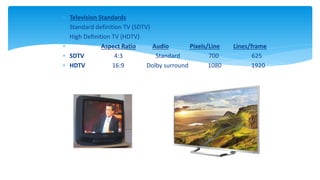
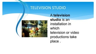
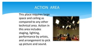
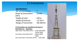
PRESENTATION ON
SUMMER
TRAINING AT
DDK, ALLAHABAD
ANKUR GUPTA
B.TECH VII (SEMESTER)
ROLL NO. 1111030008
DEPARTMENT OF ELECTRONICS ENGINEERING
I.E.R.T. ALLAHABAD
INTRODUCTION
TV STUDIO
TRANSMISSION
OVERVIEW
INTRODUCTION
 LARGEST BOARDCASTING
ORGANISATION
 1ST SERVICE STARTED ON 15TH
SEP,1959
 Doordarshan = Distant + Show.
 Doordarshan is an Indian public service
broadcaster.
 One of the largest broadcasting
organizations in India in terms of the
infrastructure of studios and transmitters.
 Terrestrial television in India
started in Delhi on 15
September 1959.
 The regular daily transmission
started in 1965 as a part of All
India Radio.
 Television services were
separated from radio in 1976.
 In 1982 color TV was
introduced in the Indian market.
 NTSC-National television standards committee(US) (525
Horizontal & 60 vertical lines)
 SECAM-System electronics for colour avec memoire
(FRANCE)(625 vertical & 50 horizantal lines)
 PAL- Phase Alternating lines(GERMANY)(625 horizontal & 50
vertical line)
Television standards used in India is PAL
TELEVISION STANDARDS
 Television Standards
 Standard definition TV (SDTV)
 High Definition TV (HDTV)
 Aspect Ratio Audio Pixels/Line Lines/frame
 SDTV 4:3 Standard 700 625
 HDTV 16:9 Dolby surround 1080 1920
A television
studio is an
installation in
which
television or video
productions take
place .
TELEVISION STUDIO
 ACTION AREA
 PRODUCTION CONTROL ROOM
 CENTRAL APPARATUS ROOM
Activities in a television studio can be
divided into three major areas such as :
ACTION AREA
This place requires large
space and ceiling as
compared to any other
technical area. Action in
this area includes
staging, lighting,
performance by artists,
and arrangement to pick
up picture and sound.
• MONITOR
PROGRAM AND
GRAPHICS
• VISION MIXER (to
select video
sources)
• Audio console
• Add video effect
PRODUCTION CONTROL ROOM
CENTRAL APPARATUS ROOM
 Includes the power supply unit
 UPS room
 Generator
COMPONENTS OF TV STUDIO
• Camera
• Lighting
• Microphones
• Vision mixer and Audio
Console
• MSR(Master Switching
Room)
• VTR
• Acoustics
• Post Production and Video
Effects
• Supporting Services like
UPS,AC
CAMERA OPTICS
A TV Camera consists of four sections.
• Camera lens and optics - To form optical image
on the face plate of a pick up device. The lens
for a video camera has following sections :-
Focus - To form a focused optical image.
Zoom Section - A lens with a variable focal length is called as Zoom lens.
For getting different composition of pictures like long shot or
close up, lens with variable focal length is required.
Aperture or Iris Control - Intensity of the light can be controlled by
changing the Iris of the camera. Iris can be operated in
manual mode or it can be automatic mode.
• Optical Block - Optical Block consists of filters and beam splitter. Beam splitter
splits the incoming light into three beams i.e. red, green and blue.
• Transducer or pick up device - To convert optical image into an electrical signal.
• Electronics - To process output of a transducer to get a Colour Composite Video
Signal. (CCVS).
Basic Three Point Lighting
Key light : This is the principle light for illumination. It gives shape and modeling by
casting shadows. It is treated like "sun" in the sky and it should cast only one shadow.
Normally it is a hard source.
Fill Light : Controls the lighting contrast by filling in shadows. It can also provide catch
lights in the eyes. Normally it is a soft source.
Back Light : Separates the person from the background, reveals background interest
and shape. Normally it is hard source.
Background Light : Separates the person from the background, reveals background
interest and shape. Normally it is hard source.
In three point lighting the ratio of 3/2/1 (Back/Key/Fill) for mono and 3/2/2 for colour
provides good portrait lighting.
Light Sources
Light source fall into two categories :-
1. Hard : A Hard Source behaves as a point source and casts a single hard edged
shadow.
2. Soft : A Soft Source behaves as a large area source taking into account the relative
size of object and light source and the distance separating them.
TV Transmission
Specifications:
No. of transmitters : 2
Power of transmitters : 10 KW
(HPT)
Height of mast : 150 m
Height of antenna : 15-20 m
Range of Transmitter : 80-100 Km
TV Transmitters are classified on the basis of
their Power of Operation:
High Power Transmitter (HPT) : 1 kW, 5kW,10kW,
20 KW, 30kW
Low Power Transmitter (LPT) : 100W, 300W,
500W
Very Low Power Transmitter (VLPT) : 10W, 50W
• An antenna (or aerial) is a transducer
designed to transmit or receive
electromagnetic waves. In other words,
antennas convert electromagnetic
waves into electrical currents and vice
versa.
ANTENNA & SATELLITE
TYPES OF ANTENNA
• Isotropic antenna (idealized)
o Radiates power equally
in all directions
• Dipole antennas
o Half-wave dipole
antenna (or Hertz
antenna)
o Quarter-wave vertical
antenna (or Marconi
antenna)
• Parabolic Dish / Reflective Antenna
 http://inventors.about.com/od/tstartinventions/a/Television.htm
 http://en.wikipedia.org/wiki/Broadcast_television_systems
 http://www.althos.com/tutorial/TV-advertising-tutorial-broadcast-
television-system.html
 http://www.scribd.com/doc/44694977/Modern-Communication-Systems-
PART-1-TELEVISION
 http://www.danalee.ca/ttt/transmission.htm
RESOURCES
DOORDARSHAN KENDRA SUMMER TRAINING REPORT

DOORDARSHAN KENDRA SUMMER TRAINING REPORT

  • 1.
    PRESENTATION ON SUMMER TRAINING AT DDK,ALLAHABAD ANKUR GUPTA B.TECH VII (SEMESTER) ROLL NO. 1111030008 DEPARTMENT OF ELECTRONICS ENGINEERING I.E.R.T. ALLAHABAD
  • 2.
  • 3.
    INTRODUCTION  LARGEST BOARDCASTING ORGANISATION 1ST SERVICE STARTED ON 15TH SEP,1959  Doordarshan = Distant + Show.  Doordarshan is an Indian public service broadcaster.  One of the largest broadcasting organizations in India in terms of the infrastructure of studios and transmitters.
  • 4.
     Terrestrial televisionin India started in Delhi on 15 September 1959.  The regular daily transmission started in 1965 as a part of All India Radio.  Television services were separated from radio in 1976.  In 1982 color TV was introduced in the Indian market.
  • 5.
     NTSC-National televisionstandards committee(US) (525 Horizontal & 60 vertical lines)  SECAM-System electronics for colour avec memoire (FRANCE)(625 vertical & 50 horizantal lines)  PAL- Phase Alternating lines(GERMANY)(625 horizontal & 50 vertical line) Television standards used in India is PAL TELEVISION STANDARDS
  • 6.
     Television Standards Standard definition TV (SDTV)  High Definition TV (HDTV)  Aspect Ratio Audio Pixels/Line Lines/frame  SDTV 4:3 Standard 700 625  HDTV 16:9 Dolby surround 1080 1920
  • 7.
    A television studio isan installation in which television or video productions take place . TELEVISION STUDIO
  • 8.
     ACTION AREA PRODUCTION CONTROL ROOM  CENTRAL APPARATUS ROOM Activities in a television studio can be divided into three major areas such as :
  • 9.
    ACTION AREA This placerequires large space and ceiling as compared to any other technical area. Action in this area includes staging, lighting, performance by artists, and arrangement to pick up picture and sound.
  • 10.
    • MONITOR PROGRAM AND GRAPHICS •VISION MIXER (to select video sources) • Audio console • Add video effect PRODUCTION CONTROL ROOM
  • 11.
    CENTRAL APPARATUS ROOM Includes the power supply unit  UPS room  Generator
  • 12.
    COMPONENTS OF TVSTUDIO • Camera • Lighting • Microphones • Vision mixer and Audio Console • MSR(Master Switching Room) • VTR • Acoustics • Post Production and Video Effects • Supporting Services like UPS,AC
  • 13.
    CAMERA OPTICS A TVCamera consists of four sections. • Camera lens and optics - To form optical image on the face plate of a pick up device. The lens for a video camera has following sections :- Focus - To form a focused optical image. Zoom Section - A lens with a variable focal length is called as Zoom lens. For getting different composition of pictures like long shot or close up, lens with variable focal length is required. Aperture or Iris Control - Intensity of the light can be controlled by changing the Iris of the camera. Iris can be operated in manual mode or it can be automatic mode. • Optical Block - Optical Block consists of filters and beam splitter. Beam splitter splits the incoming light into three beams i.e. red, green and blue. • Transducer or pick up device - To convert optical image into an electrical signal. • Electronics - To process output of a transducer to get a Colour Composite Video Signal. (CCVS).
  • 14.
    Basic Three PointLighting Key light : This is the principle light for illumination. It gives shape and modeling by casting shadows. It is treated like "sun" in the sky and it should cast only one shadow. Normally it is a hard source. Fill Light : Controls the lighting contrast by filling in shadows. It can also provide catch lights in the eyes. Normally it is a soft source. Back Light : Separates the person from the background, reveals background interest and shape. Normally it is hard source. Background Light : Separates the person from the background, reveals background interest and shape. Normally it is hard source. In three point lighting the ratio of 3/2/1 (Back/Key/Fill) for mono and 3/2/2 for colour provides good portrait lighting. Light Sources Light source fall into two categories :- 1. Hard : A Hard Source behaves as a point source and casts a single hard edged shadow. 2. Soft : A Soft Source behaves as a large area source taking into account the relative size of object and light source and the distance separating them.
  • 15.
    TV Transmission Specifications: No. oftransmitters : 2 Power of transmitters : 10 KW (HPT) Height of mast : 150 m Height of antenna : 15-20 m Range of Transmitter : 80-100 Km TV Transmitters are classified on the basis of their Power of Operation: High Power Transmitter (HPT) : 1 kW, 5kW,10kW, 20 KW, 30kW Low Power Transmitter (LPT) : 100W, 300W, 500W Very Low Power Transmitter (VLPT) : 10W, 50W
  • 16.
    • An antenna(or aerial) is a transducer designed to transmit or receive electromagnetic waves. In other words, antennas convert electromagnetic waves into electrical currents and vice versa. ANTENNA & SATELLITE
  • 17.
    TYPES OF ANTENNA •Isotropic antenna (idealized) o Radiates power equally in all directions • Dipole antennas o Half-wave dipole antenna (or Hertz antenna) o Quarter-wave vertical antenna (or Marconi antenna) • Parabolic Dish / Reflective Antenna
  • 18.
     http://inventors.about.com/od/tstartinventions/a/Television.htm  http://en.wikipedia.org/wiki/Broadcast_television_systems http://www.althos.com/tutorial/TV-advertising-tutorial-broadcast- television-system.html  http://www.scribd.com/doc/44694977/Modern-Communication-Systems- PART-1-TELEVISION  http://www.danalee.ca/ttt/transmission.htm RESOURCES