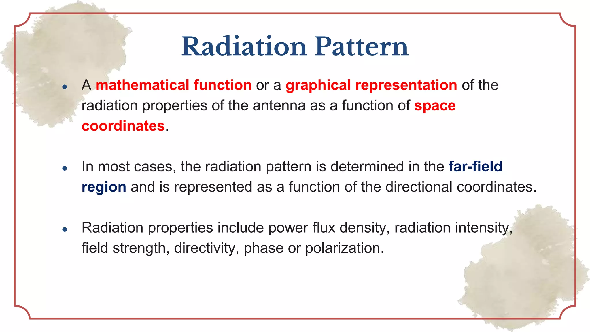
ANTENNAS AND
RADIATING SYSTEMS
Lecture 1
Dr. Jeet Ghosh
Assistant Professor
E.C.E
C.B.I.T
Unit 1
Basic Antenna Parameter
Radiation Pattern, Radiation Power
Density, Radiation Intensity,
Directivity, Gain, Antenna efficiency,
Beam efficiency, Bandwidth,
Polarization, Input
Impedance,
Antenna Effective length and area
.
Radiation Mechanism
.Why and how the antennas are
radiate?
Region of Separation
Near Field and Far Field.
FRISS TRANSMISSION
EQUATION
.
Antenna Temperature, Antenna
vector effective length,
Radiation
Mechanisim
01
Definition of Antenna
A means for radiating or receiving radio
waves
In other words the antenna is the
transitional structure between free-space
and a guiding device.
The guiding device or transmission line
may take the form of a coaxial line or a
hollow pipe (waveguide), and it is used to
transport electromagnetic energy from the
transmitting source to the antenna, or from
the antenna to the receiver.
RL= Dielectric Loss, Conduction Loss
Rr = Antenna radiation resistance
XA= Antenna reactance
Under ideal conditions, energy generated by the source should be totally transferred to
the radiation resistance Rr, which is used to represent radiation by the antenna.
However, in a practical system there are conduction-dielectric losses due to the lossy
nature of the transmission line and the antenna, as well as those due to reflections
(mismatch) losses at the interface between the line and the antenna.
Radiation Mechanism
+ -
Electrostatic Scenario
Magnetostatic Scenerio
For the above cases,
Static E field and
Static H Field
generated, No wave is
generated
For wave, we need a
time varying current
For the radiation, the current should be time varying. If the current is time
varying or charges are accelerating in any form, there is a possibility of
radiation.
Can this circuit radiate??
Radiation Condition
1. If a charge is not moving, current is not created and there is no
radiation.
2. If charge is moving with a uniform velocity:
a. There is no radiation if the wire is straight, and infinite in
extent.
b. There is radiation if the wire is curved, bent, discontinuous,
terminated, or truncated.
3. If charge is oscillating in a time-motion, it radiates even if the wire is
straight
Radiation Mechanism – Two wire
Parameter of Antenna –
Radiation Pattern
Radiation Pattern
● A mathematical function or a graphical representation of the
radiation properties of the antenna as a function of space
coordinates.
● In most cases, the radiation pattern is determined in the far-field
region and is represented as a function of the directional coordinates.
● Radiation properties include power flux density, radiation intensity,
field strength, directivity, phase or polarization.
● Often the field and power patterns are normalized with respect to their
maximum value, yielding normalized field and power patterns.
Also, the power pattern is usually plotted on a logarithmic scale or
more commonly in decibels (dB).
● Field pattern (in linear scale) typically represents a plot of the
magnitude of the electric or magnetic field as a function of the angular
space
● Power pattern (in linear scale) typically represents a plot of the
square of the magnitude of the electric or magnetic field as a function
of the angular space.
● Power pattern (in dB) represents the magnitude of the electric or
magnetic field, in decibels, as a function of the angular space.
In this and subsequent
patterns, the plus (+) and
minus (-) signs in the lobes
indicate the relative
polarization (positive or
negative) of the amplitude
between the various lobes,
which changes (alternates)
as the nulls are crossed.
Radiation Lobe
● A radiation lobe is a “portion of the radiation pattern bounded by
regions of relatively weak radiation intensity.
● Radiation lobe can be different type
○ Major lobe
○ Minor Lobe
○ Side Lobe
○ Back Lobe
● A major lobe (also called main beam) is defined as “the radiation lobe
containing the direction of maximum radiation.”
● A side lobe is “a radiation lobe in any direction other than the intended lobe.”
(Usually a side lobe is adjacent to the main lobe and occupies the hemisphere
in the direction of the main beam.)
● A back lobe is “a radiation lobe whose axis makes an angle of approximately
180◦ with respect to the beam of an antenna.”
● Minor lobes usually represent radiation in undesired directions, and they
should be minimized. Side lobes are normally the largest of the minor lobes.
The level of minor lobes is usually expressed as a ratio of the power density in
the lobe in question to that of the major lobe. This ratio is often termed the
side lobe ratio or side lobe level. Side lobe levels of -20 dB or smaller are
usually not desirable in most applications.
Understanding of E plane and H
Plane
X
Z
Y
E Plane = XZ
H Plane = YX
Different type of Radiation Pattern
Radiation
Pattern
Isotropic Omnidirectional Directional
Isotropic Radiator
● A hypothetical lossless antenna having equal radiation in all
directions.
● Although it is ideal and not physically realizable, it is often taken as a
reference for expressing the directive properties of actual antennas.
Directional Radiator
● A directional antenna is one “having
the property of radiating or receiving
electromagnetic waves more
effectively in some directions than in
others.
● This term is usually applied to an
antenna whose maximum directivity
is significantly greater than that of a
half-wave dipole
Omnidirectional Radiator
Having an essentially nondirectional pattern in a given plane (in this case
in azimuth) and a directional pattern in any orthogonal plane (in this case
in elevation)
Field Region
Radiation Field
Near Field
Reactive Near
Field
Radiative Near
Field
Far Field
Reactive Near
Field
● Portion of the near-field
region immediately
surrounding the antenna
wherein the reactive field
predominates
Reactive Near
Field
● For most antennas, the
outer
boundary of this region is
commonly taken to exist at a
distance R < 0.62√D3∕λ from
the antenna surface, where
λ is the wavelength and D is
the largest dimension of the
antenna.
Reactive Near
Field
● For a very short dipole, or
equivalent radiator, the outer
boundary is commonly taken
to exist at a distance λ∕2𝜋
from the antenna surface.
Radiative Near
Field
● region of the field of an
antenna between the
reactive near-field region
and the far-field region
wherein radiation fields
predominate and
wherein the angular field
distribution is dependent
upon the distance from the
antenna.
Radiative Near
Field
● If the antenna has a
maximum dimension that
is not large compared to
the wavelength, this
region may not exist.
Radiative Near
Field
● The inner boundary is taken
to be the distance R ≥
0.62√D3∕λ and the outer
boundary the distance R <
2D2∕λ where D is the largest
dimension of the antenna.
Far Field
● Region of the field of an
antenna where the angular
field distribution is
essentially independent of
the distance from the
antenna.
● If the antenna has a
maximum overall dimension
D, the far-field region is
commonly taken to exist at
distances greater
than 2D2∕λ from the antenna,
Far Field
● In physical media, if the antenna has
a maximum overall dimension, D,
which is large compared to 𝜋∕|𝛾|,
the far-field region can be taken to
begin approximately at a distance
equal to |𝛾|D2∕𝜋 from the antenna, 𝛾
being the propagation constant in
the medium.
● In this region, the field
components are essentially
transverse and the angular
distribution is independent of
the radial distance where the
measurements are made
Angular Field
distribution is vary
with radial
distance
Angular Field
distribution is
independent with
radial distance
Radian and Steradian
● Radian:
One radian is defined as the plane angle with its vertex at the center of a
circle of radius r that is subtended by an arc whose length is r .
r
r
1 radian
● Steradian
● The measure of a solid angle is a steradian. One steradian is defined
as the solid angle with its vertex at the center of a sphere of radius r
that is subtended by a spherical surface area equal to that of a square
with each side of length r
𝑑𝐴 = 𝑟2
sin 𝜃 𝑑𝜃 𝑑𝜙
𝑑Ω =
𝑑𝐴
𝑟2
= sin 𝜃 𝑑𝜃 𝑑𝜙
Problem
For a sphere of radius r, find the solid angle ΩA (in square radians or
steradians) of a spherical cap on the surface of the sphere over the north-pole
region defined by spherical angles of 0 ≤ 𝜃 ≤ 30◦, 0 ≤ 𝜙 ≤ 360◦.
𝑑Ω =
𝑑𝐴
𝑟2
= sin 𝜃 𝑑𝜃 𝑑𝜙
Ω = ∫ 𝑑Ω = ∫
0
2𝜋
∫
0
𝜋
6 sin 𝜃 𝑑𝜃𝑑𝜙 = 2𝜋 − cos 𝜃 0
𝜋
6
= 2𝜋[−0.867 + 1] = 2𝜋(0.133) = 0.83566
RADIATION INTENSITY
● The power radiated from an antenna per unit solid angle
●
Beam Width
● Half-Power Beamwidth (HPBW), : “In a plane containing the direction
of the maximum of a beam, the angle between the two directions in
which the radiation intensity is one-half value of the beam.”
● First-Null Beamwidth (FNBW) : The angle between the two first null of
the pattern is FNBW
Problem
● Find out the FNBW of U(𝜃) = cos2(𝜃) cos2(3𝜃)
For FNBW, we need to find out the null
𝑈 𝜃 = 0
cos2
𝜃 cos2
3 𝜃 = 0
cos 𝜃 = 0; ⇒ 𝜃 = ±
𝜋
2
cos 3𝜃 = 0; ⇒ 𝜃 = ±
𝜋
6
First null occur at ±
𝜋
6
position
So, FNBW= 2 ×
𝜋
6
= 𝜋/3
Directivity of the Antenna
● The ratio of the radiation intensity in a given direction from the
antenna to the radiation intensity averaged over all directions
So, 𝐷 =
𝑈
𝑈0
U = Radiation intensity in a given direction
U0 = Avg. Radiation intensity 𝑈𝑜 =
𝑃𝑟𝑎𝑑
4𝜋
𝐷 =
4𝜋𝑈
𝑃𝑟𝑎𝑑
f the direction is not specified, it implies the direction of maximum radiation intensity
(maximum directivity) expressed as
𝐷𝑀𝑎𝑥 =
4𝜋𝑈𝑚𝑎𝑥
𝑃𝑟𝑎𝑑
● The total directivity is the sum of the partial directivities for any two
orthogonal polarizations.
●
Discussion on Directivity
● Let discuss about the two radiation pattern
○ U1= A sin()
○ U2 = A sin2 ()
Plot in MATLAB
Which one is more directive?
Half wavelength Dipole
At this four point Dipole
radiator have the same
directivity with an isotropic
radiator.
𝐷 = 1.67 sin3
𝜃 = 1
sin 𝜃 =
1
1.67
1
3
; 𝜃 = 57.440
, 122.560
The directivity of an isotropic source is unity since its power is radiated equally
well in all directions. For all other sources, the maximum directivity will always
be greater than unity, and it is a relative “figure of merit” which gives an indication
of the directional properties of the antenna as compared with those of an
isotropic source.
The directivity can be smaller than unity; in fact it can be equal to zero. For
Examples in dipole, the directivity is equal to zero in the 𝜃 = 0 direction.
The values of directivity will be equal to or greater than zero and equal to
or less than the maximum directivity
𝐷 =
4𝜋𝑈
𝑃𝑟𝑎𝑑
We know,
For 3-D pattern,
𝐷 =
4𝜋𝑈
𝑃𝑟𝑎𝑑
We know,
For 3-D pattern,
It can be approximated
as
Antenna Efficiency
Loss due to reflection
Conduction loss
Dielectric loss
Gain
● The gain of the antenna is closely related to the directivity, it is a
measure that takes into account the efficiency of the antenna as well
as its directional capabilities.
●
● For 3 D pattern
● The approximate formula for Gain
●
Beam Efficiency
●
●
If 𝜃1 is chosen as the angle where the
first null or minimum occurs, then the
beam
efficiency will indicate the amount of
power in the major lobe compared to the
total power
Input Impedance
● Defined as “ the impedance presented by an antenna as its terminals
or
● The ratio of the voltage to current at a pair of terminals
or
● The ratio of the appropriate components of the electric to magnetic fields
at a point
Input Impedance
• Terminals are designated as a − b.
• The ratio of the voltage to current at these
terminals, with no load attached, defines the
impedance of the antenna as
• If we assume that the antenna is attached to a
generator with internal impedance
where
• Rg = resistance of generator impedance (ohms)
• Xg = reactance of generator impedance (ohms)
and the antenna is used in the transmitting mode, we can
represent the antenna and generator by an equivalent
circuit shown in fig.b
1
2
Input Impedance
Educational Purpose Only
69
• To find the amount of power delivered to Rr for
radiation and the amount dissipated in RL as heat
(I2RL/2).
• First find the current developed within the loop
which is given by
• Where Vg is the peak generator voltage. The power delivered
to the antenna for radiation is given by
3
4
5
6
Input Impedance
Educational Purpose Only
70
• The remaining power is dissipated as heat on the
internal resistance Rs of the generator & it is
given by
• The maximum power delivered to the antenna occurs when we
have conjugate matching
• From eqn 10-12 it is clear that
8
9
10
13
7
11
12
Antenna Effective Length
● The effective length of an antenna, whether it be a linear or an
aperture antenna, is a quantity that is used to determine the voltage
induced on the open-circuit terminals of the antenna when a wave
impinges upon it.
Antenna Effective Aperture
● The ratio of the available power at the terminals of a receiving
antenna to the power flux density of a plane wave incident on the
antenna from that direction, the wave being polarization-matched to
the antenna. If the direction is not specified, the direction of maximum
radiation intensity is implied.
Using the maximum power transfer
theorem
Maximum Effective Aperture
Effective scattering area
Effective Loss Area
Capture area
● Antenna maximum effective area is related with the directivity
Aperture Efficiency
Friss transmission equation
Tx Ant.
Rx Ant.
Let, this ant. is isotropic radiated
power Pt
Friss transmission equation
Tx Ant.
Rx Ant.
If the antenna is directive then
Friss transmission equation
Tx Ant.
Rx Ant.
Polarization
ARS 01.01.pptx

ARS 01.01.pptx

  • 1.
    ANTENNAS AND RADIATING SYSTEMS Lecture1 Dr. Jeet Ghosh Assistant Professor E.C.E C.B.I.T
  • 2.
    Unit 1 Basic AntennaParameter Radiation Pattern, Radiation Power Density, Radiation Intensity, Directivity, Gain, Antenna efficiency, Beam efficiency, Bandwidth, Polarization, Input Impedance, Antenna Effective length and area . Radiation Mechanism .Why and how the antennas are radiate? Region of Separation Near Field and Far Field. FRISS TRANSMISSION EQUATION . Antenna Temperature, Antenna vector effective length,
  • 3.
  • 4.
    Definition of Antenna Ameans for radiating or receiving radio waves
  • 5.
    In other wordsthe antenna is the transitional structure between free-space and a guiding device. The guiding device or transmission line may take the form of a coaxial line or a hollow pipe (waveguide), and it is used to transport electromagnetic energy from the transmitting source to the antenna, or from the antenna to the receiver.
  • 6.
    RL= Dielectric Loss,Conduction Loss Rr = Antenna radiation resistance XA= Antenna reactance
  • 7.
    Under ideal conditions,energy generated by the source should be totally transferred to the radiation resistance Rr, which is used to represent radiation by the antenna. However, in a practical system there are conduction-dielectric losses due to the lossy nature of the transmission line and the antenna, as well as those due to reflections (mismatch) losses at the interface between the line and the antenna.
  • 8.
  • 9.
  • 10.
    For the abovecases, Static E field and Static H Field generated, No wave is generated For wave, we need a time varying current
  • 12.
    For the radiation,the current should be time varying. If the current is time varying or charges are accelerating in any form, there is a possibility of radiation. Can this circuit radiate??
  • 13.
    Radiation Condition 1. Ifa charge is not moving, current is not created and there is no radiation. 2. If charge is moving with a uniform velocity: a. There is no radiation if the wire is straight, and infinite in extent. b. There is radiation if the wire is curved, bent, discontinuous, terminated, or truncated. 3. If charge is oscillating in a time-motion, it radiates even if the wire is straight
  • 14.
  • 15.
    Parameter of Antenna– Radiation Pattern
  • 16.
    Radiation Pattern ● Amathematical function or a graphical representation of the radiation properties of the antenna as a function of space coordinates. ● In most cases, the radiation pattern is determined in the far-field region and is represented as a function of the directional coordinates. ● Radiation properties include power flux density, radiation intensity, field strength, directivity, phase or polarization.
  • 17.
    ● Often thefield and power patterns are normalized with respect to their maximum value, yielding normalized field and power patterns. Also, the power pattern is usually plotted on a logarithmic scale or more commonly in decibels (dB).
  • 19.
    ● Field pattern(in linear scale) typically represents a plot of the magnitude of the electric or magnetic field as a function of the angular space ● Power pattern (in linear scale) typically represents a plot of the square of the magnitude of the electric or magnetic field as a function of the angular space. ● Power pattern (in dB) represents the magnitude of the electric or magnetic field, in decibels, as a function of the angular space.
  • 21.
    In this andsubsequent patterns, the plus (+) and minus (-) signs in the lobes indicate the relative polarization (positive or negative) of the amplitude between the various lobes, which changes (alternates) as the nulls are crossed.
  • 22.
    Radiation Lobe ● Aradiation lobe is a “portion of the radiation pattern bounded by regions of relatively weak radiation intensity. ● Radiation lobe can be different type ○ Major lobe ○ Minor Lobe ○ Side Lobe ○ Back Lobe
  • 23.
    ● A majorlobe (also called main beam) is defined as “the radiation lobe containing the direction of maximum radiation.” ● A side lobe is “a radiation lobe in any direction other than the intended lobe.” (Usually a side lobe is adjacent to the main lobe and occupies the hemisphere in the direction of the main beam.) ● A back lobe is “a radiation lobe whose axis makes an angle of approximately 180◦ with respect to the beam of an antenna.” ● Minor lobes usually represent radiation in undesired directions, and they should be minimized. Side lobes are normally the largest of the minor lobes. The level of minor lobes is usually expressed as a ratio of the power density in the lobe in question to that of the major lobe. This ratio is often termed the side lobe ratio or side lobe level. Side lobe levels of -20 dB or smaller are usually not desirable in most applications.
  • 25.
    Understanding of Eplane and H Plane X Z Y E Plane = XZ H Plane = YX
  • 26.
    Different type ofRadiation Pattern Radiation Pattern Isotropic Omnidirectional Directional
  • 27.
    Isotropic Radiator ● Ahypothetical lossless antenna having equal radiation in all directions. ● Although it is ideal and not physically realizable, it is often taken as a reference for expressing the directive properties of actual antennas.
  • 28.
    Directional Radiator ● Adirectional antenna is one “having the property of radiating or receiving electromagnetic waves more effectively in some directions than in others. ● This term is usually applied to an antenna whose maximum directivity is significantly greater than that of a half-wave dipole
  • 29.
    Omnidirectional Radiator Having anessentially nondirectional pattern in a given plane (in this case in azimuth) and a directional pattern in any orthogonal plane (in this case in elevation)
  • 30.
    Field Region Radiation Field NearField Reactive Near Field Radiative Near Field Far Field
  • 31.
    Reactive Near Field ● Portionof the near-field region immediately surrounding the antenna wherein the reactive field predominates
  • 32.
    Reactive Near Field ● Formost antennas, the outer boundary of this region is commonly taken to exist at a distance R < 0.62√D3∕λ from the antenna surface, where λ is the wavelength and D is the largest dimension of the antenna.
  • 33.
    Reactive Near Field ● Fora very short dipole, or equivalent radiator, the outer boundary is commonly taken to exist at a distance λ∕2𝜋 from the antenna surface.
  • 34.
    Radiative Near Field ● regionof the field of an antenna between the reactive near-field region and the far-field region wherein radiation fields predominate and wherein the angular field distribution is dependent upon the distance from the antenna.
  • 35.
    Radiative Near Field ● Ifthe antenna has a maximum dimension that is not large compared to the wavelength, this region may not exist.
  • 36.
    Radiative Near Field ● Theinner boundary is taken to be the distance R ≥ 0.62√D3∕λ and the outer boundary the distance R < 2D2∕λ where D is the largest dimension of the antenna.
  • 37.
    Far Field ● Regionof the field of an antenna where the angular field distribution is essentially independent of the distance from the antenna. ● If the antenna has a maximum overall dimension D, the far-field region is commonly taken to exist at distances greater than 2D2∕λ from the antenna,
  • 38.
    Far Field ● Inphysical media, if the antenna has a maximum overall dimension, D, which is large compared to 𝜋∕|𝛾|, the far-field region can be taken to begin approximately at a distance equal to |𝛾|D2∕𝜋 from the antenna, 𝛾 being the propagation constant in the medium. ● In this region, the field components are essentially transverse and the angular distribution is independent of the radial distance where the measurements are made
  • 39.
    Angular Field distribution isvary with radial distance Angular Field distribution is independent with radial distance
  • 40.
    Radian and Steradian ●Radian: One radian is defined as the plane angle with its vertex at the center of a circle of radius r that is subtended by an arc whose length is r . r r 1 radian
  • 41.
    ● Steradian ● Themeasure of a solid angle is a steradian. One steradian is defined as the solid angle with its vertex at the center of a sphere of radius r that is subtended by a spherical surface area equal to that of a square with each side of length r
  • 42.
    𝑑𝐴 = 𝑟2 sin𝜃 𝑑𝜃 𝑑𝜙 𝑑Ω = 𝑑𝐴 𝑟2 = sin 𝜃 𝑑𝜃 𝑑𝜙
  • 43.
    Problem For a sphereof radius r, find the solid angle ΩA (in square radians or steradians) of a spherical cap on the surface of the sphere over the north-pole region defined by spherical angles of 0 ≤ 𝜃 ≤ 30◦, 0 ≤ 𝜙 ≤ 360◦. 𝑑Ω = 𝑑𝐴 𝑟2 = sin 𝜃 𝑑𝜃 𝑑𝜙 Ω = ∫ 𝑑Ω = ∫ 0 2𝜋 ∫ 0 𝜋 6 sin 𝜃 𝑑𝜃𝑑𝜙 = 2𝜋 − cos 𝜃 0 𝜋 6 = 2𝜋[−0.867 + 1] = 2𝜋(0.133) = 0.83566
  • 44.
    RADIATION INTENSITY ● Thepower radiated from an antenna per unit solid angle ●
  • 45.
    Beam Width ● Half-PowerBeamwidth (HPBW), : “In a plane containing the direction of the maximum of a beam, the angle between the two directions in which the radiation intensity is one-half value of the beam.” ● First-Null Beamwidth (FNBW) : The angle between the two first null of the pattern is FNBW
  • 47.
    Problem ● Find outthe FNBW of U(𝜃) = cos2(𝜃) cos2(3𝜃) For FNBW, we need to find out the null 𝑈 𝜃 = 0 cos2 𝜃 cos2 3 𝜃 = 0 cos 𝜃 = 0; ⇒ 𝜃 = ± 𝜋 2 cos 3𝜃 = 0; ⇒ 𝜃 = ± 𝜋 6 First null occur at ± 𝜋 6 position So, FNBW= 2 × 𝜋 6 = 𝜋/3
  • 48.
    Directivity of theAntenna ● The ratio of the radiation intensity in a given direction from the antenna to the radiation intensity averaged over all directions So, 𝐷 = 𝑈 𝑈0 U = Radiation intensity in a given direction U0 = Avg. Radiation intensity 𝑈𝑜 = 𝑃𝑟𝑎𝑑 4𝜋 𝐷 = 4𝜋𝑈 𝑃𝑟𝑎𝑑 f the direction is not specified, it implies the direction of maximum radiation intensity (maximum directivity) expressed as 𝐷𝑀𝑎𝑥 = 4𝜋𝑈𝑚𝑎𝑥 𝑃𝑟𝑎𝑑
  • 49.
    ● The totaldirectivity is the sum of the partial directivities for any two orthogonal polarizations. ●
  • 50.
    Discussion on Directivity ●Let discuss about the two radiation pattern ○ U1= A sin() ○ U2 = A sin2 () Plot in MATLAB Which one is more directive?
  • 51.
  • 52.
    At this fourpoint Dipole radiator have the same directivity with an isotropic radiator. 𝐷 = 1.67 sin3 𝜃 = 1 sin 𝜃 = 1 1.67 1 3 ; 𝜃 = 57.440 , 122.560
  • 53.
    The directivity ofan isotropic source is unity since its power is radiated equally well in all directions. For all other sources, the maximum directivity will always be greater than unity, and it is a relative “figure of merit” which gives an indication of the directional properties of the antenna as compared with those of an isotropic source. The directivity can be smaller than unity; in fact it can be equal to zero. For Examples in dipole, the directivity is equal to zero in the 𝜃 = 0 direction. The values of directivity will be equal to or greater than zero and equal to or less than the maximum directivity
  • 54.
  • 55.
  • 56.
    It can beapproximated as
  • 57.
    Antenna Efficiency Loss dueto reflection Conduction loss Dielectric loss
  • 59.
    Gain ● The gainof the antenna is closely related to the directivity, it is a measure that takes into account the efficiency of the antenna as well as its directional capabilities. ●
  • 60.
    ● For 3D pattern
  • 61.
    ● The approximateformula for Gain ●
  • 62.
    Beam Efficiency ● ● If 𝜃1is chosen as the angle where the first null or minimum occurs, then the beam efficiency will indicate the amount of power in the major lobe compared to the total power
  • 63.
    Input Impedance ● Definedas “ the impedance presented by an antenna as its terminals or ● The ratio of the voltage to current at a pair of terminals or ● The ratio of the appropriate components of the electric to magnetic fields at a point
  • 64.
    Input Impedance • Terminalsare designated as a − b. • The ratio of the voltage to current at these terminals, with no load attached, defines the impedance of the antenna as • If we assume that the antenna is attached to a generator with internal impedance where • Rg = resistance of generator impedance (ohms) • Xg = reactance of generator impedance (ohms) and the antenna is used in the transmitting mode, we can represent the antenna and generator by an equivalent circuit shown in fig.b 1 2
  • 65.
    Input Impedance Educational PurposeOnly 69 • To find the amount of power delivered to Rr for radiation and the amount dissipated in RL as heat (I2RL/2). • First find the current developed within the loop which is given by • Where Vg is the peak generator voltage. The power delivered to the antenna for radiation is given by 3 4 5 6
  • 66.
    Input Impedance Educational PurposeOnly 70 • The remaining power is dissipated as heat on the internal resistance Rs of the generator & it is given by • The maximum power delivered to the antenna occurs when we have conjugate matching • From eqn 10-12 it is clear that 8 9 10 13 7 11 12
  • 67.
    Antenna Effective Length ●The effective length of an antenna, whether it be a linear or an aperture antenna, is a quantity that is used to determine the voltage induced on the open-circuit terminals of the antenna when a wave impinges upon it.
  • 68.
    Antenna Effective Aperture ●The ratio of the available power at the terminals of a receiving antenna to the power flux density of a plane wave incident on the antenna from that direction, the wave being polarization-matched to the antenna. If the direction is not specified, the direction of maximum radiation intensity is implied.
  • 69.
    Using the maximumpower transfer theorem
  • 70.
  • 71.
    Maximum Effective Aperture Effectivescattering area Effective Loss Area Capture area
  • 72.
    ● Antenna maximumeffective area is related with the directivity
  • 73.
  • 74.
    Friss transmission equation TxAnt. Rx Ant. Let, this ant. is isotropic radiated power Pt
  • 75.
    Friss transmission equation TxAnt. Rx Ant. If the antenna is directive then
  • 76.
  • 78.