Download as PDF, PPTX

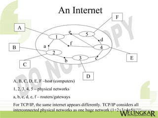
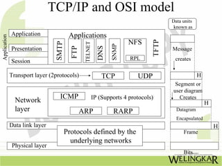
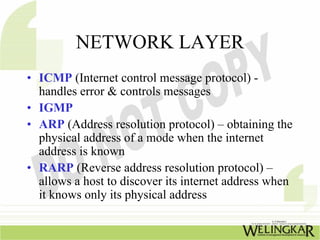
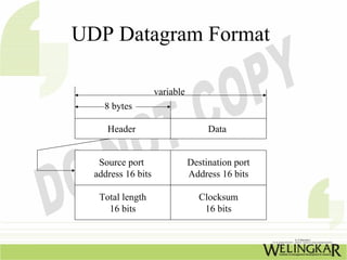
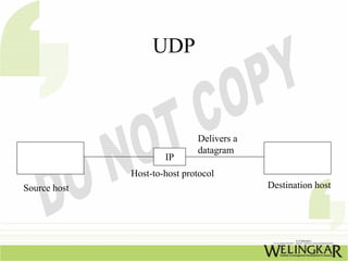
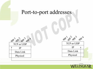
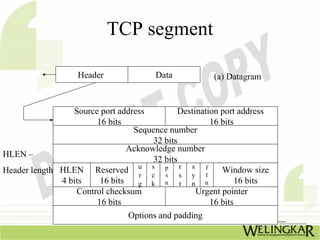
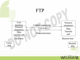
The document provides an overview of the Transmission Control Protocol (TCP) and Internet Protocol (IP), detailing their history, functionality, and how they facilitate error-free communication over networks. It explains TCP/IP as a crucial networking standard and the significance of different protocol layers, including IP datagrams and error-handling mechanisms like ICMP. Additionally, it covers various Internet addressing schemes and applications such as Telnet, FTP, and the World Wide Web.