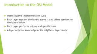
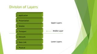
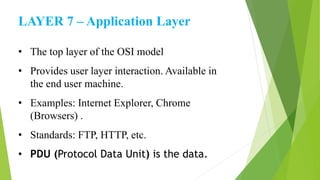
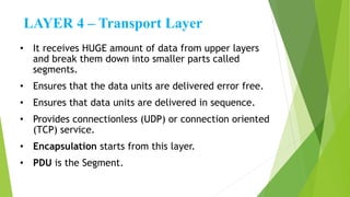
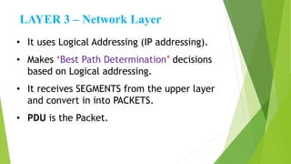
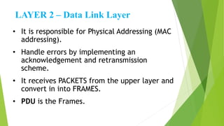
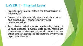
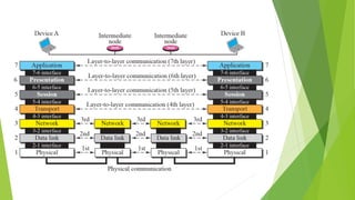
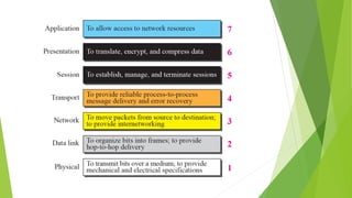
The OSI Model
Presentation by: Shubham Pendharkar
 Established in 1947, the International Standards Organization
(ISO) is a multinational body dedicated to worldwide agreement
on international standards. Almost three-fourths of countries in
the world are represented in the ISO. An ISO standard that
covers all aspects of network communications is the Open
System Interconnection (OSI) model. It was first introduced in
the late 1970s.
 Open Systems Interconnection (OSI)
 Each layer support the layers above it and offers services to
the layers below
 Each layer performs unique and specific task
 A layer only has knowledge of its neighbour layers only
Introduction to the OSI Model
Why OSI Model was created ?
 An attempt to make a framework for developing
networking technologies.
 A framework is helpful in the design of hardware and
software for communication.
 ISO-OSI Model serves this purpose.
 OSI became a tool for explaining the Networking in
general.
Division of Layers
Upper Layers
Lower Layers
Middle Layer
6. Presentation
5. Session
4. Transport
3. Network
2. Data Link
1. Physical
7. Application
Application Layer
Presentation Layer
Session Layer
Transport Layer
Network Layer
Data Link Layer
Physical Layer
Aao
Pyar
Se
Tuhme
Networking
De
Padhaye
LAYER 7 – Application Layer
• The top layer of the OSI model
• Provides user layer interaction. Available in
the end user machine.
• Examples: Internet Explorer, Chrome
(Browsers) .
• Standards: FTP, HTTP, etc.
• PDU (Protocol Data Unit) is the data.
LAYER 6– Presentation Layer
• It ensures that data transferred from
application layer of one system can be read
by application layer of other system.
• Tasks which can be performed:
* Compression
* Decompression
* Encryption
* Decryption
• PDU is the data.
LAYER 5 – Session Layer
• Session layer provides mechanism for
controlling the dialogue between the two
end systems. It defines how to start, control
and end conversations (called sessions)
between applications.
• Any necessary log-on or password validation
is also handled by this layer.
• PDU is the data.
LAYER 4 – Transport Layer
• It receives HUGE amount of data from upper layers
and break them down into smaller parts called
segments.
• Ensures that the data units are delivered error free.
• Ensures that data units are delivered in sequence.
• Provides connectionless (UDP) or connection oriented
(TCP) service.
• Encapsulation starts from this layer.
• PDU is the Segment.
LAYER 3 – Network Layer
• It uses Logical Addressing (IP addressing).
• Makes ‘Best Path Determination’ decisions
based on Logical addressing.
• It receives SEGMENTS from the upper layer
and convert in into PACKETS.
• PDU is the Packet.
LAYER 2 – Data Link Layer
• It is responsible for Physical Addressing (MAC
addressing).
• Handle errors by implementing an
acknowledgement and retransmission
scheme.
• It receives PACKETS from the upper layer and
convert in into FRAMES.
• PDU is the Frames.
LAYER 1 – Physical Layer
• Provides physical interface for transmission of
information.
• Covers all - mechanical, electrical, functional
and procedural - aspects for physical
communication.
• Such characteristics as voltage levels, timing of
voltage changes, physical data rates, maximum
transmission distances, physical connectors, and
other similar attributes are defined by physical
layer specifications.
Thank You

OSI Model

  • 1.
    The OSI Model Presentationby: Shubham Pendharkar
  • 2.
     Established in1947, the International Standards Organization (ISO) is a multinational body dedicated to worldwide agreement on international standards. Almost three-fourths of countries in the world are represented in the ISO. An ISO standard that covers all aspects of network communications is the Open System Interconnection (OSI) model. It was first introduced in the late 1970s.
  • 3.
     Open SystemsInterconnection (OSI)  Each layer support the layers above it and offers services to the layers below  Each layer performs unique and specific task  A layer only has knowledge of its neighbour layers only Introduction to the OSI Model
  • 4.
    Why OSI Modelwas created ?  An attempt to make a framework for developing networking technologies.  A framework is helpful in the design of hardware and software for communication.  ISO-OSI Model serves this purpose.  OSI became a tool for explaining the Networking in general.
  • 5.
    Division of Layers UpperLayers Lower Layers Middle Layer 6. Presentation 5. Session 4. Transport 3. Network 2. Data Link 1. Physical 7. Application
  • 6.
    Application Layer Presentation Layer SessionLayer Transport Layer Network Layer Data Link Layer Physical Layer Aao Pyar Se Tuhme Networking De Padhaye
  • 7.
    LAYER 7 –Application Layer • The top layer of the OSI model • Provides user layer interaction. Available in the end user machine. • Examples: Internet Explorer, Chrome (Browsers) . • Standards: FTP, HTTP, etc. • PDU (Protocol Data Unit) is the data.
  • 8.
    LAYER 6– PresentationLayer • It ensures that data transferred from application layer of one system can be read by application layer of other system. • Tasks which can be performed: * Compression * Decompression * Encryption * Decryption • PDU is the data.
  • 9.
    LAYER 5 –Session Layer • Session layer provides mechanism for controlling the dialogue between the two end systems. It defines how to start, control and end conversations (called sessions) between applications. • Any necessary log-on or password validation is also handled by this layer. • PDU is the data.
  • 10.
    LAYER 4 –Transport Layer • It receives HUGE amount of data from upper layers and break them down into smaller parts called segments. • Ensures that the data units are delivered error free. • Ensures that data units are delivered in sequence. • Provides connectionless (UDP) or connection oriented (TCP) service. • Encapsulation starts from this layer. • PDU is the Segment.
  • 11.
    LAYER 3 –Network Layer • It uses Logical Addressing (IP addressing). • Makes ‘Best Path Determination’ decisions based on Logical addressing. • It receives SEGMENTS from the upper layer and convert in into PACKETS. • PDU is the Packet.
  • 12.
    LAYER 2 –Data Link Layer • It is responsible for Physical Addressing (MAC addressing). • Handle errors by implementing an acknowledgement and retransmission scheme. • It receives PACKETS from the upper layer and convert in into FRAMES. • PDU is the Frames.
  • 13.
    LAYER 1 –Physical Layer • Provides physical interface for transmission of information. • Covers all - mechanical, electrical, functional and procedural - aspects for physical communication. • Such characteristics as voltage levels, timing of voltage changes, physical data rates, maximum transmission distances, physical connectors, and other similar attributes are defined by physical layer specifications.
  • 18.