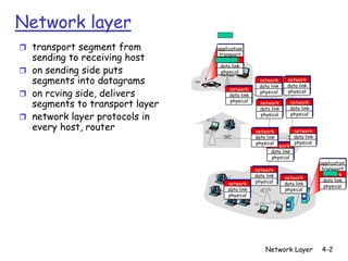
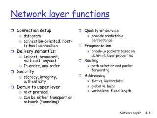
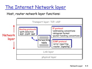
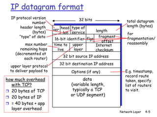
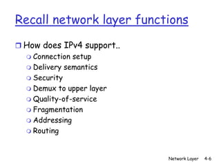
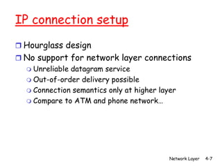
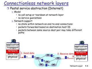
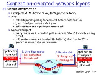
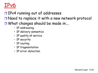
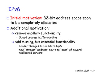
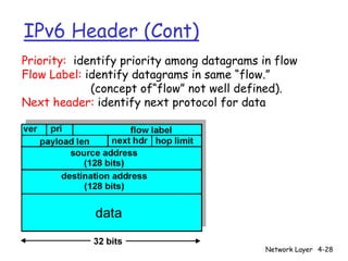
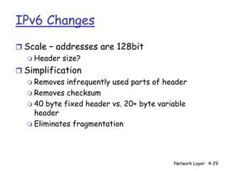
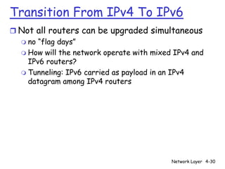
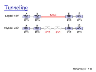
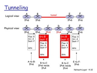
2. Network layer
r transport segment from application
sending to receiving host transport
network
data link
r on sending side puts physical
segments into datagrams network
data link
network
data link
network
r on rcving side, delivers data link
physical physical
segments to transport layer physical network
data link
network
data link
r network layer protocols in physical physical
every host, router network network
data link data link
physical physical
network
data link
physical
application
network transport
data link network
network
physical data link
network data link
physical
data link physical
physical
Network Layer 4-2
3. Network layer functions
r Connection setup r Quality-of-service
m datagram m provide predictable
m connection-oriented, host- performance
to-host connection r Fragmentation
r Delivery semantics: m break-up packets based on
m Unicast, broadcast, data-link layer properties
multicast, anycast r Routing
m In-order, any-order m path selection and packet
r Security forwarding
m secrecy, integrity, r Addressing
authenticity m flat vs. hierarchical
r Demux to upper layer m global vs. local
m next protocol m variable vs. fixed length
m Can be either transport or
network (tunneling)
Network Layer 4-3
4. The Internet Network layer
Host, router network layer functions:
Transport layer: TCP, UDP
Routing protocols IP protocol
•path selection •addressing conventions
•RIP, OSPF, BGP •datagram format
Network •packet handling conventions
layer forwarding
ICMP protocol
table
•error reporting
•router “signaling”
Link layer
physical layer
Network Layer 4-4
5. IP datagram format
IP protocol version 32 bits
number total datagram
header length length (bytes)
ver head. type of length
(bytes) len service for
“type” of data fragment
16-bit identifier flgs fragmentation/
offset
max number time to upper reassembly
Internet
remaining hops live layer checksum
(decremented at
32 bit source IP address
each router)
32 bit destination IP address
upper layer protocol
to deliver payload to Options (if any) E.g. timestamp,
record route
how much overhead data taken, specify
with TCP? (variable length, list of routers
r 20 bytes of TCP typically a TCP to visit.
or UDP segment)
r 20 bytes of IP
r = 40 bytes + app
layer overhead
Network Layer 4-5
6. Recall network layer functions
r How does IPv4 support..
m Connection setup
m Delivery semantics
m Security
m Demux to upper layer
m Quality-of-service
m Fragmentation
m Addressing
m Routing
Network Layer 4-6
7. IP connection setup
r Hourglass design
r No support for network layer connections
m Unreliable datagram service
m Out-of-order delivery possible
m Connection semantics only at higher layer
m Compare to ATM and phone network…
Network Layer 4-7
8. Connectionless network layers
r Postal service abstraction (Internet)
m Model
• no call setup or teardown at network layer
• no service guarantees
m Network support
• no state within network on end-to-end connections
• packets forwarded based on destination host ID
• packets between same source-dest pair may take different
paths
application
application
transport
transport
network
network
data link 1. Send data 2. Receive data
data link
physical
physical
Network Layer 4-8
9. Connection-oriented network layers
r Circuit abstraction
m Examples: ATM, frame relay, X.25, phone network
m Model
• call setup and signaling for each call before data can flow
• guaranteed performance during call
• call teardown and signaling to remove call
m Network support
• every router on source-dest path maintains “state” for each passing
circuit
• link, router resources (bandwidth, buffers) allocated to VC to
guarantee circuit-like performance
application 5. Data flow begins 6. Receive data application
transport 4. Call connected transport
3. Accept call
network 1. Initiate call network
data link 2. incoming call
data link
physical physical
Network Layer 4-9
10. IP delivery semantics
r No reliability guarantees
m Loss
r No ordering guarantees
m Out-of-order delivery possible
r Unicast mostly
m IP broadcast (255.255.255.255) not forwarded
m IP multicast supported, but not widely used
• 224.0.0.0 to 239.255.255.255
Network Layer 4-10
11. IP security
r Weak support for integrity
m IP checksum
• IP has a header checksum, leaves data integrity to TCP/UDP
• http://www.rfc-editor.org/rfc/rfc1141.txt
m No support for secrecy, authenticity
r IPsec
m Retrofit IP network layer with encryption and
authentication
m http://www.rfc-editor.org/rfc/rfc2411.txt
Network Layer 4-11
12. IP demux to upper layer
r http://www.rfc-editor.org/rfc/rfc1700.txt
m Protocol type field
• 1 = ICMP
• 4 = IP in IP
• 6 = TCP
• 8 = EGP
• 9 = IGP
• 17 = UDP
Network Layer 4-12
13. IP quality of service
r IP originally had “type-of-service” (TOS) field to
eventually support quality
m Not used, ignored by most routers
r Need to provide applications with performance
guarantees
m Mid 90s: Add circuits to the Internet!
• Integrated services (intserv) and RSVP signalling
• Per-flow end-to-end QoS support
• Per-flow signaling and network resource allocation
Network Layer 4-13
14. Network service model
Example services for Example services for a
individual datagrams: flow of datagrams:
r guaranteed delivery r in-order datagram
r guaranteed delivery delivery
with less than 40 msec r guaranteed minimum
delay bandwidth to flow
r restrictions on
changes in inter-
packet spacing (jitter)
Network Layer 4-14
15. IP quality of service
r Protocols developed and standardized
m RSVP signalling protocol
m Intserv service models
r Failed miserably…Why?
m Complexity
• Scheduling
• Routing (pinning routes)
• Per-flow signalling overhead
m Lack of scalability
• Per-flow state
m Economics
• Providers with no incentive to deploy
• SLA, end-to-end billing issues
m QoS a weak-link property
• Requires every device on an end-to-end basis to support flow
Network Layer 4-15
16. IP quality of service
r Now it’s diffserv…
m Use the “type-of-service” bits as a priority marking
m http://www.rfc-editor.org/rfc/rfc2474.txt
m http://www.rfc-editor.org/rfc/rfc2475.txt
m http://www.rfc-editor.org/rfc/rfc2597.txt
m http://www.rfc-editor.org/rfc/rfc2598.txt
Network Layer 4-16
17. IP Addressing
r IP address:
223.1.1.1
m 32-bit identifier for
host/router 223.1.1.2
223.1.2.1
interface 223.1.1.4 223.1.2.9
m routers typically have
223.1.2.2
multiple interfaces 223.1.1.3 223.1.3.27
m Addresses hierarchical
(like post office)
223.1.3.1 223.1.3.2
223.1.1.1 = 11011111 00000001 00000001 00000001
223 1 1 1
Network Layer 4-17
18. IP Addressing
r IP address:
m network part (high order
223.1.1.1
bits) 223.1.2.1
m host part (low order bits)
223.1.1.2
223.1.1.4 223.1.2.9
r What’s a network ?
m all interfaces that can 223.1.1.3 223.1.3.27
223.1.2.2
physically reach each
other without intervening LAN
router
m each interface shares 223.1.3.1 223.1.3.2
the same network part of
IP address
network consisting of 3 IP networks
(for IP addresses starting with 223,
first 24 bits are network address)
Network Layer 4-18
19. How did networks get IP addresses?
r Total IP address size: 4 billion
r Initially one large class (8-bit network, 24-bit host)
m ISP given an 8-bit network number to manage
m Each router keeps track of each network (28=256 routes)
m Each network has 16 million hosts
m Problem: one size does not fit all
r Classful addressing
m Accommodate smaller networks (LANs)
m Class A: 128 networks, 16M hosts
m Class B: 16K networks, 64K hosts
m Class C: 2M networks, 256 hosts
m Total routes potentially > 2,113,664 networks and network routes !
Network Layer 4-19
20. IP address classes
8 16 24 32
Class A 0 Network ID Host ID
1.0.0.0 to 127.255.255.255
Class B 10 Network ID Host ID
128.0.0.0 to 191.255.255.255
Class C 110 Network ID Host ID
192.0.0.0 to 223.255.255.255
Class D 1110 Multicast Addresses
224.0.0.0 to 239.255.255.255
Class E 1111 Reserved for experiments
Network Layer 4-20
21. Special IP Addresses
r Private addresses
– http://www.rfc-editor.org/rfc/rfc1918.txt
– Class A: 10.0.0.0 - 10.255.255.255 (10.0.0.0/8 prefix)
– Class B: 172.16.0.0 - 172.31.255.255 (172.16.0.0/12
prefix)
– Class C: 192.168.0.0 - 192.168.255.255 (192.168.0.0/16
prefix)
r 127.0.0.1: local host (a.k.a. the loopback
address)
Network Layer 4-21
22. IP Addressing problems
r Inefficient use of address space
m Class A (rarely given out, sparse usage)
m Class B = 64k hosts (sparse usage)
• Very few LANs have close to 64K hosts
r Address space depletion
m Classes A and B take huge chunks of space but
not used much
m Not many class C addresses left to give out
r Explosion of routes
m Increasing use of class C explodes # of routes
Network Layer 4-22
23. IP addressing: CIDR
r Original classful addressing
m Use class structure (A, B, C) to determine
network ID for route lookup
r CIDR: Classless InterDomain Routing
m Arbitrarily
aggregate and split up adjacent
network addresses
variable
network host
part part
11001000 00010111 00010000 00000000
200.23.16.0/23
Network Layer 4-23
24. CIDR
r Assign any range of addresses to network
m Allows one to split large network blocks into multiple
smaller ones (increase usage of Class A & B)
m Allows one to combine small network blocks into a
single large one (reduce routes from Class C usage)
Network Layer 4-24
25. Getting IP addresses
Q: How does network get IP addresses?
A: organization gets allocated portion of its provider
ISP’s address space
m ISPs get it from ICANN: Internet Corporation for
Assigned Names and Numbers
• Allocates addresses, manages DNS, resolves disputes
m Customers get sub-blocks from ISPs
ISP's block 11001000 00010111 00010000 00000000 200.23.16.0/20
Organization 0 11001000 00010111 00010000 00000000 200.23.16.0/23
Organization 1 11001000 00010111 00010010 00000000 200.23.18.0/23
Organization 2 11001000 00010111 00010100 00000000 200.23.20.0/23
... ….. …. ….
Organization 7 11001000 00010111 00011110 00000000 200.23.30.0/23
Network Layer 4-25
26. IPv6
r IPv4 running out of addresses
r Need to replace it with a new network protocol
r What changes should be made in….
• IP addressing
• IP delivery semantics
• IP quality of service
• IP security
• IP routing
• IP fragmentation
• IP error detection
Network Layer 4-26
27. IPv6
r Initial motivation: 32-bit address space soon
to be completely allocated
r Additional motivation:
m Remove ancillary functionality
• Speed processing/forwarding
m Add missing, but essential functionality
• header changes to facilitate QoS
• new “anycast” address: route to “best” of several
replicated servers
Network Layer 4-27
28. IPv6 Header (Cont)
Priority: identify priority among datagrams in flow
Flow Label: identify datagrams in same “flow.”
(concept of“flow” not well defined).
Next header: identify next protocol for data
Network Layer 4-28
29. IPv6 Changes
r Scale – addresses are 128bit
m Header size?
r Simplification
m Removes infrequently used parts of header
m Removes checksum
m 40 byte fixed header vs. 20+ byte variable
header
m Eliminates fragmentation
Network Layer 4-29
30. Transition From IPv4 To IPv6
r Not all routers can be upgraded simultaneous
m no “flag days”
m How will the network operate with mixed IPv4 and
IPv6 routers?
m Tunneling: IPv6 carried as payload in an IPv4
datagram among IPv4 routers
Network Layer 4-30
31. Tunneling
A B E F
Logical view: tunnel
IPv6 IPv6 IPv6 IPv6
A B E F
Physical view:
IPv6 IPv6 IPv4 IPv4 IPv6 IPv6
Network Layer 4-31
32. Tunneling
A B E F
Logical view: tunnel
IPv6 IPv6 IPv6 IPv6
A B C D E F
Physical view:
IPv6 IPv6 IPv4 IPv4 IPv6 IPv6
Flow: X Src:B Src:B Flow: X
Src: A Dest: E Dest: E Src: A
Dest: F Dest: F
Flow: X Flow: X
Src: A Src: A
data Dest: F Dest: F data
data data
A-to-B: E-to-F:
B-to-C: B-to-C:
IPv6 IPv6
IPv6 inside IPv6 inside
IPv4 IPv4
Network Layer 4-32
34. Two Key Network-Layer Functions
r forwarding: move packets from router’s
input to appropriate router output
r routing: determine route taken by
packets from source to dest.
m routing algorithms
Network Layer 4-34
35. Internet routing with IP addresses
r Hop-by-hop forwarding based on destination IP
carried by packet
m Each packet has destination IP address
m Each router has forwarding table of..
• destination IP à next hop IP address
m IP route table calculated in network routers
r Most prevalent way to route on the Internet
m Distributed routing algorithm for calculating
forwarding tables
Network Layer 4-35
36. Routing protocols
Goal: determine “good” path (sequence of routers) thru
network from source to dest.
Graph abstraction for 5
routing algorithms:
3
B C
r Routing algorithms find 2 5
minimum cost paths A 2 1 F
3
through graph 1 2
D E
1
Network Layer 4-36
37. Routing Algorithm classification
Global or decentralized information?
Global:
m all routers have complete topology, link cost info
m “link state” algorithms
Decentralized:
m router knows physically-connected neighbors, link costs
to neighbors
m iterative process of computation, exchange of info with
neighbors
m “distance vector” algorithms
Network Layer 4-37
38. Hierarchical Routing
scale: with 200 million administrative autonomy
destinations: r internet = network of
r can’t store all dest’s in networks
routing tables! r each network admin may
r routing table exchange want to control routing in its
would swamp links! own network
r Flat routing does not scale
Network Layer 4-38
39. Routing Hierarchies
r Key observation
m Need less information with increasing distance to
destination
m Hierarchical routing
• saves table size
• reduces update traffic
• allows routing to scale
Network Layer 4-39
40. Areas
r Divide network into areas
m Within area, each node has routes to every other node
m Outside area
• Each node has routes for other top-level areas only (not
nodes within those areas)
• Inter-area packets are routed to nearest appropriate border
router
Network Layer 4-40
41. Internet Routing Hierarchy
r Internet areas called Border routers
“autonomous systems” m Special routers in AS
(AS) that directly link to
m administrative another AS
autonomy • also run inter-AS
routing protocol or
r routers in same AS run border gateway
same routing protocol protocol (BGP) with
other gateway routers
m “intra-AS” routing in other AS’s
protocol (IGP)
Network Layer 4-41
43. Inter-AS routing
r Done using BGP (Border Gateway Protocol)
m Uses distance-vector style algorithms
r BGP messages exchanged using TCP.
m Advantages:
• Simplifies BGP
• No need for periodic refresh - routes are valid until
withdrawn, or the connection is lost
• Incremental updates
m Disadvantages
• BGP TCP spoofing attack
• Congestion control on a routing protocol?
• Poor interaction during high load (Code Red)
• No authentication of route advertisements
– Pakistan Youtube incident
Network Layer 4-43
44. ICMP: Internet Control Message Protocol
r Essentially a network-layer
protocol for passing control Type Code description
messages 0 0 echo reply (ping)
r used by hosts & routers to 3 0 dest. network unreachable
communicate network-level 3 1 dest host unreachable
information
3 2 dest protocol unreachable
m error reporting: unreachable
host, network, port, protocol 3 3 dest port unreachable
m echo request/reply (used by 3 6 dest network unknown
ping) 3 7 dest host unknown
r network-layer “above” IP: 4 0 source quench (congestion
m ICMP msgs carried in IP control - not used)
datagrams 8 0 echo request (ping)
r ICMP message: type, code plus 9 0 route advertisement
first 8 bytes of IP datagram
causing error
10 0 router discovery
r http://www.rfc- 11 0 TTL expired
editor.org/rfc/rfc792.txt 12 0 bad IP header
Network Layer 4-44
45. ICMP and traceroute
r What do “real” Internet delay & loss look like?
r Traceroute program: provides delay
measurement from source to router along end-end
Internet path towards destination. For all i:
m sends three packets that will reach router i on path
towards destination
m router i will return packets to sender
m sender times interval between transmission and reply.
3 probes 3 probes
3 probes
Network Layer 4-45
46. ICMP and traceroute
r Source sends series of r When ICMP message
UDP segments to dest arrives, source calculates
m First has TTL =1 RTT
m Second has TTL=2, etc. r Traceroute does this 3
m Unlikely port number times
r When nth datagram arrives Stopping criterion
to nth router: r UDP segment eventually
m Router discards datagram arrives at destination host
m And sends to source an r Destination returns ICMP
ICMP message (type 11, “host unreachable” packet
code 0) (type 3, code 3)
m Message includes name of
r When source gets this
router& IP address
ICMP, stops.
Network Layer 4-46
47. Examples
traceroute: gaia.cs.umass.edu to www.eurecom.fr
Three delay measurements from
gaia.cs.umass.edu to cs-gw.cs.umass.edu
1 cs-gw (128.119.240.254) 1 ms 1 ms 2 ms
2 border1-rt-fa5-1-0.gw.umass.edu (128.119.3.145) 1 ms 1 ms 2 ms
3 cht-vbns.gw.umass.edu (128.119.3.130) 6 ms 5 ms 5 ms
4 jn1-at1-0-0-19.wor.vbns.net (204.147.132.129) 16 ms 11 ms 13 ms
5 jn1-so7-0-0-0.wae.vbns.net (204.147.136.136) 21 ms 18 ms 18 ms
6 abilene-vbns.abilene.ucaid.edu (198.32.11.9) 22 ms 18 ms 22 ms
7 nycm-wash.abilene.ucaid.edu (198.32.8.46) 22 ms 22 ms 22 ms trans-oceanic
8 62.40.103.253 (62.40.103.253) 104 ms 109 ms 106 ms
9 de2-1.de1.de.geant.net (62.40.96.129) 109 ms 102 ms 104 ms link
10 de.fr1.fr.geant.net (62.40.96.50) 113 ms 121 ms 114 ms
11 renater-gw.fr1.fr.geant.net (62.40.103.54) 112 ms 114 ms 112 ms
12 nio-n2.cssi.renater.fr (193.51.206.13) 111 ms 114 ms 116 ms
13 nice.cssi.renater.fr (195.220.98.102) 123 ms 125 ms 124 ms
14 r3t2-nice.cssi.renater.fr (195.220.98.110) 126 ms 126 ms 124 ms
15 eurecom-valbonne.r3t2.ft.net (193.48.50.54) 135 ms 128 ms 133 ms
16 194.214.211.25 (194.214.211.25) 126 ms 128 ms 126 ms
17 * * *
18 * * * * means no response (probe lost, router not replying)
19 fantasia.eurecom.fr (193.55.113.142) 132 ms 128 ms 136 ms
Network Layer 4-47
48. Try it
r Some routers labeled with airport code of
city they are located in
m traceroute www.yahoo.com
• Packets go to SEA, back to PDX, SJC
m traceroute www.oregonlive.com
• Packets go to SMF, SFO, SJC, NYC, EWR.
m traceroute www.uoregon.edu
• Packets go to Pittock block to Eugene
m traceroute www.lclark.edu
• Packets go to SEA and back to PDX
Network Layer 4-48