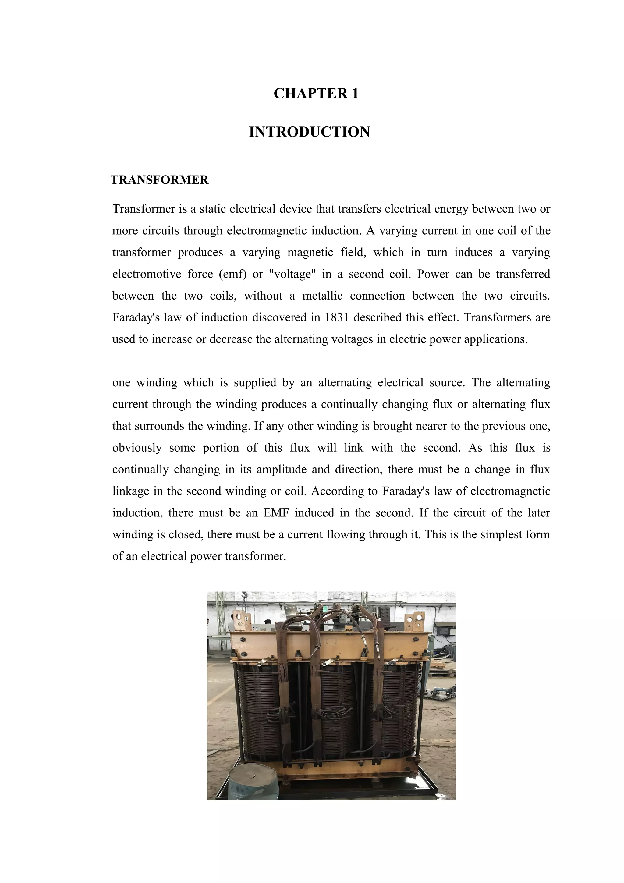
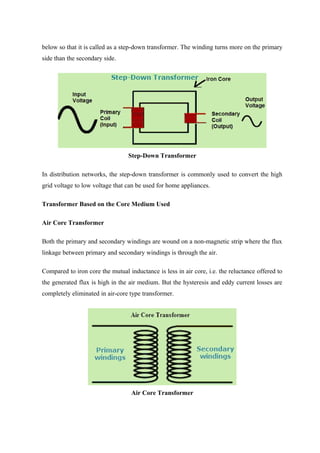
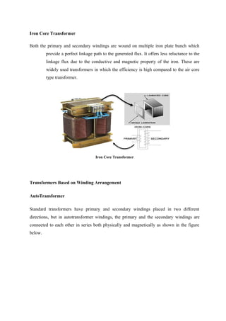
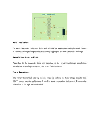
Transformers are static electrical devices that transfer energy between circuits through electromagnetic induction, functioning to step up or step down alternating voltages without changing frequency. They consist of three main parts: primary winding, magnetic core, and secondary winding, utilizing the principles of electromagnetism and Faraday's law of electromagnetic induction. Various configurations and designs exist, including core type and shell type transformers, each with distinct winding arrangements and purposes based on voltage requirements and applications.

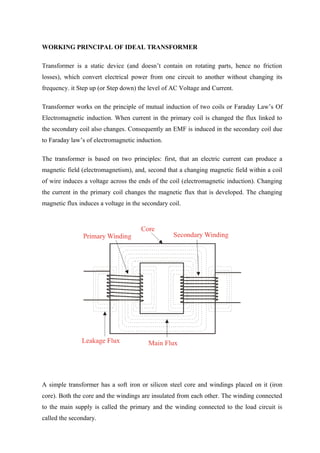
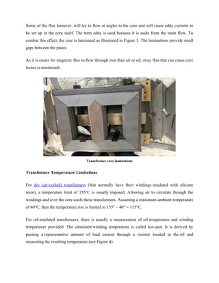
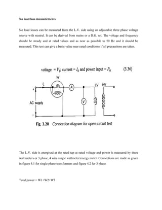
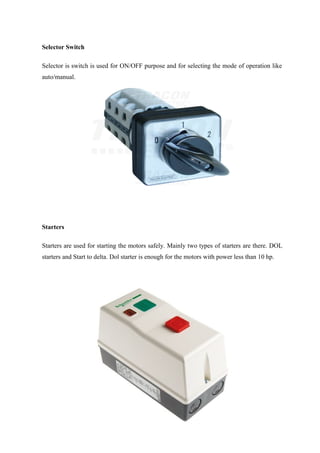
![This results in the decrease of the performance of the transformer and the tearing of the
turn-to-turn ratio. The main reasons that cause this fault are the improper repair, bad
maintenance, corrosion, manufacturing deficiencies, vibration and mechanical movement
within the transformer.
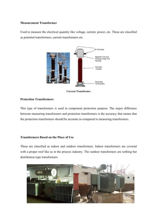
Bushing Failure
Bushes are insulating devices that insulate a high voltage electrical conductor to pass
through an earth conductor. In transformers it provides a current path through the tank
wall. Inside the transformer paper insulators are used which are surrounded by oil that
provides further insulation. Bushing failure usually occurs over time [5]. Bushes failure
PN number is between 24 to 48. Some of the main reasons for bushing failure are
discussed below.
A. Loosening of conductors is caused by transformer vibrations which results in
overheating. This heat damage the insulating paper and the oil used.
B. sudden high fault voltages causes’ partial discharge (breakdown of solid/liquid
electrical insulators) which damage the bushes and causes its degeneration and
complete breakdown within hours.
C. Seal breaking of bushes happen due to ingress of water, aging or excessive
dielectric losses. Due to this fault core failure of the transformer occurs.
D. Not replacing of old oil over long time or its deficiency due to leakage causes
internal over-flashing.
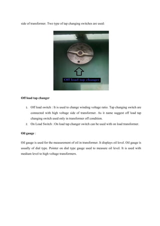
Tap Changer Failure
The tap changer function in the transformer is to regulate the voltage level. This is
done by either adding or removing turns from the secondary transformer winding. It is
the most complex part of the transformer and also an important one. Even the
smallest fault results in the wrong power output. The PN number is usually between
28 to 52.
Some fault and causes are](https://image.slidesharecdn.com/transformersee-180619105245/85/Transformers-ee-24-320.jpg)
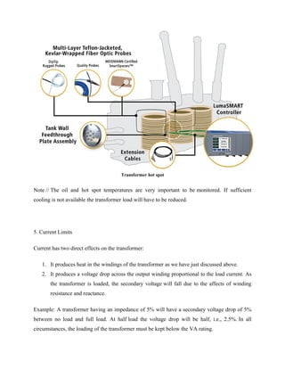
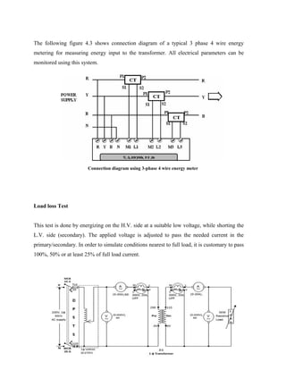
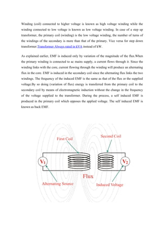
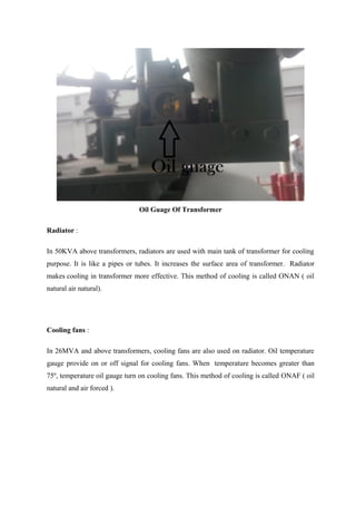
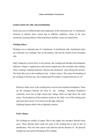
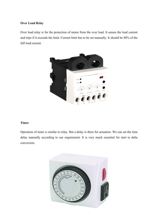
![Control Panel
Panels are used for the protection of transformer. The different protection schemes of
transformer are employed by using panels. Panels mainly serve the purpose of control and
giving indication of the faults that occur.
Types of Panel
Electric Panel
● Marshalling Box - [Fan, pump, CT, 4-20V Analog ]
● RTCC - Remote Tap Changer Control Cubical - [Raise, Lower, AVR, RWTI,
ROTI, RTPI etc]
● TJB- Thermo Junction Box [Only for WTI & OTI]
● CM. Box - Common Marshalling Box
● DM Box - Drive Mechanism Box - [Raise Lower]](https://image.slidesharecdn.com/transformersee-180619105245/85/Transformers-ee-41-320.jpg)


![REFRENCES
[1] www.wikipedia.org
[2] www.electrical4u.com
[3] www.google images.com
[4] www.electricaleasy.com
[5] www.google.co.in
[6] www.quora.com
[7] www.ieee.com
[8] www.electricalengineeringschools.com
[9] www.learn.adafruit.com
[10] www.what-when- how.com
*********](https://image.slidesharecdn.com/transformersee-180619105245/85/Transformers-ee-53-320.jpg)


![Chapter_3-Transformers[1]-1.pdf](https://cdn.slidesharecdn.com/ss_thumbnails/chapter3-transformers1-1-230622173423-be6efc48-thumbnail.jpg?width=640&height=640&fit=bounds)


