03/29/2025 Instrumentation andSensors 1
Sensors
• A measuring device passes through two stages while measuring a
signal.
• First, the measurand is sensed and then, the measured signal is
transuded (or converted) into a form that is particularly suitable for
transmitting, signal conditioning, processing, or driving a controller
or actuator.
• For this reason, output of the transducer stage is often an electrical
signal.
2.
2
What Is ALoad Cell And How Does It Work?
• A load cell is an electro-mechanical sensor used to measure force
or weight. It has a simple yet effective design which relies upon the
well-known transference between an applied force, material
deformation and the flow of electricity.
4
• When weuse load cells, one end is usually secured to a frame or base, while the
other end is free to attach the weight or weight-bearing element.
• When force is applied to the body of the load cell, it flexes slightly under the
strain. This is similar to what happens to a fishing rod when a fisherman hooks a
fish.
• The fisherman will secure the rod in their hands while the fish applies a pulling
force on the other end of the fishing line. The result of this force is that the fishing
rod bends, with a bigger, stronger fish, causing the bend to be more extreme.
• When this action happens to a load sensor, the deformation is very subtle and not
visible to the naked eye. To measure the deformation, strain gages are tightly
bonded to the body of the load cell at pre-determined points, causing them to
deform in unison with the body. The resulting movement alters the electrical
resistance of the strain gages in proportion to the amount of deformation caused
by the applied load.
• Using signal conditioning electronics, the electrical resistance of the strain gages
can be measured with the resulting signal being output as a weight or force
reading.
03/29/2025 Instrumentation andSensors 6
Transducer
• The word “Transducer” is the collective term used for
both Sensors which can be used to sense a wide range of different
energy forms such as movement, electrical signals, radiant energy,
thermal or magnetic energy etc, and Actuators which can be used to
switch voltages or currents
7.
03/29/2025 Instrumentation andSensors 7
Sensor vs Transducer
The terms sensor and transducer are often used interchangeably, but they
have distinct meanings in the context of measurement and instrumentation.
Here's the key difference:
Sensor:
• A sensor is a device that detects or measures a physical quantity (e.g.,
temperature, pressure, light, motion) and converts it into a signal that can
be observed or recorded.
• The output of a sensor is typically an electrical signal (e.g., voltage,
current, or resistance) or a digital signal.
• Key Function: Detection and measurement of a physical quantity.
• Example: A thermistor measures temperature and changes its resistance
accordingly.
8.
8
Sensor vs Transducer
Transducer:
•A transducer is a broader term that refers to any device that
converts one form of energy into another.
• It can act as a sensor, but it can also perform the reverse function
(e.g., converting electrical energy into mechanical energy).
• Key Function: Energy conversion (input energy → output
energy).
• Example: A piezoelectric transducer converts mechanical stress
into an electrical signal (sensor function) or converts an
electrical signal into mechanical vibration (actuator function).
9.
9
Remember:
• A sensoris specifically designed to detect and measure physical
quantities, while a transducer is a more general device that
converts energy from one form to another.
• All sensors are transducers (because they convert physical
quantities into electrical signals), but not all transducers are
sensors (e.g., actuators like motors or speakers are transducers but
not sensors).
This distinction is important in fields like instrumentation, control
systems, and robotics, where both sensors and transducers play
critical roles.
10.
03/29/2025 Instrumentation andSensors 10
So, one way to define is that the output from a sensor may or may not be meaningful i.e
most of the times it needs to be conditioned and converted into various other forms. The
transducer output is always meaningful.
11.
03/29/2025 Instrumentation andSensors 11
The output of a motor is meaningful. The output of a loudspeaker is meaningful.
They are transducers.
A sensor is nothing but just a primary element which senses any physical
phenomenon or it gives an indication in any change of the physical
phenomenon.
Every transducer is also(or has) a sensor but every sensor need not be a
transducer!!!.
12.
03/29/2025 Instrumentation andSensors 12
Criteria for selection of
Sensor
• Type of Sensing: The parameter that is being sensed like temperature or pressure.
Considerations:
• Application Requirements: Match the sensor type to the application's specific needs.
• Sensor Availability: Availability of sensors for the required measurement.
• Operating Principle: The principle of operation of the sensor.
Considerations:
Compatibility with Application: Ensure the sensor's operating principle suits the application environment
(e.g., optical sensors for light measurement, piezoelectric sensors for pressure).
Reliability and Stability: Choose a principle that offers long-term reliability and stability in the given
conditions.
• Power Consumption: The power consumed by the sensor will play an important role in defining the total
power of the system.
• Considerations:
• Energy Efficiency: Low power consumption is critical for battery-operated or energy-harvesting systems.
• System Power Budget: Ensure the sensor's power requirements align with the overall system power
budget.
• Accuracy: The accuracy of the sensor is a key factor in selecting a sensor.
Considerations:
• Measurement Precision: High accuracy is crucial for applications requiring precise data.
• Application Tolerance: The level of accuracy needed based on the application's tolerance for error.
13.
13
• Environmental Conditions:The conditions in which the sensor is being used will be a factor in
choosing the quality of a sensor.
Considerations:
• Environmental Robustness: Choose sensors designed to withstand the specific environmental
conditions (e.g., waterproof sensors for outdoor use).
• Operating Range: Ensure the sensor can operate within the expected environmental conditions.
• Cost: The financial cost of the sensor, including initial purchase price and potential long-term
costs.
Considerations:
• Budget Constraints: Balance the cost against the performance and quality required.
• Cost vs. Benefit: Evaluate the cost in relation to the sensor's benefits and importance to the
application.
• Resolution and Range: The smallest value that can be sensed and the limit of measurement are
important.
• Calibration and Repeatability: Change of values with time and ability to repeat measurements
under similar conditions.
14.
14
Example Application
• Let’sconsider selecting a temperature sensor for an industrial process control system:
1.Type of Sensing: Temperature
2.Operating Principle: Options could include thermocouples (thermoelectric effect), RTDs
(resistance changes with temperature), or thermistors (resistive temperature sensing).
3.Power Consumption: If the system is part of a larger wired setup, power consumption might
be less critical. However, for a remote or battery-operated system, an RTD might be preferred
over a thermocouple due to typically lower power requirements.
4.Accuracy: An RTD provides high accuracy and stability, suitable for precise industrial control.
5.Environmental Conditions: The sensor should withstand high temperatures, potential
exposure to chemicals, and mechanical vibrations. A robust housing and protective measures
might be necessary.
6.Cost: RTDs are generally more expensive than thermocouples but provide better accuracy and
stability, justifying the cost for critical applications.
7.Resolution and Range: The chosen RTD should have a sufficient range to cover the expected
temperature variations in the process, and a resolution that aligns with the required precision.
8.Calibration and Repeatability: RTDs typically have excellent repeatability and are relatively
easy to calibrate, making them suitable for continuous, long-term use in process control.
15.
15
• Mechanical Transducer
•Mechanical transducers convert
physical quantities (such as
displacement, force, pressure, or
velocity) into another form of
mechanical energy or a readable
output.
Types and Examples
Bourdon Tube:
Application: Pressure
measurement
• Strain Gauge:
• Application: Measuring
strain (deformation) in
structures.
• Accelerometers:
• Application: Measuring
acceleration.
• Electrical Transducer
• Electrical transducers convert
physical quantities into electrical
signals, facilitating the
measurement, processing, and
control of these quantities.
• Resistive inductive and capacitive
Types and Examples:
Thermocouples:
Application: Temperature
measurement.
• Piezoelectric Sensors:
• Application: Measuring
pressure, acceleration, or force.
16.
03/29/2025 Instrumentation andSensors 16
From above list, whereas many of the mechanical sensors transduce the
input to displacement, many of the electrical sensors change displacement
to an electrical output.
This is quite fortunate, for it yields practical combinations in which the
mechanical sensor serves as the primary transducers and the electrical
transducers as the secondary.
Advantages of an mechano-electric transducer:
1. Amplification or attenuation can be easily obtained.
2. Mass-inertia effects are minimized
3. The effects of friction are minimized
4. An output power of almost any magnitude can be provided
5. Remote indication or recording is feasible
6. The transducer can often be miniaturized
17.
17
Sensors Examples
1.Piezoelectric Sensors:
•Amplification: Signals from piezoelectric sensors can be easily amplified for use in
microphones and accelerometers.
• Mass-Inertia Effects: These sensors are highly sensitive and can detect minute
vibrations without the delay caused by mass and inertia.
2.Strain Gauges:
• Friction Effects: Strain gauges have no moving parts, thus eliminating friction-related
issues.
• Output Power: The electrical resistance change in strain gauges can be used to provide
signals of varying magnitudes through proper circuit design.
3.Capacitive Sensors:
• Remote Indication: Capacitive sensors can be used in touch screens and proximity
sensors where the signals can be transmitted and processed remotely.
• Miniaturization: Capacitive sensors are commonly miniaturized for use in
smartphones and other compact electronic devices.
4.Hall Effect Sensors:
• Versatile Power Output: Hall effect sensors can provide outputs for both low-power
applications like position sensing in smartphones and high-power applications like
current sensing in industrial machinery.
• Remote Monitoring: They are used in applications where the sensor data is transmitted
to a central processing unit for monitoring and control.
18.
18
Advantages of an
ElectricalTransducer
-> Electrical signal obtained from electrical transducer can be easily processed (mainly
amplified) and brought to a level suitable for output device which may be an indicator or
recorder.
-> The electrical systems can be controlled with a very small level of power.
-> The electrical output can be easily used, transmitted and processed for the purpose of
measurement.
-> With the advent of IC technology, the electronic systems have become extremely small in
size, requiring small space for their operation.
-> No moving mechanical parts are involved in the electrical systems. Therefore, there is no
question of mechanical wear and tear and no possibility of mechanical failure.
-> Friction effect is minimized.
-> The output can be indicated and recorded remotely from the sensing element.
-> Power requirement is very low for controlling the electrical or electronic system.
-> An amplifier may be used for amplifying the electrical signal according to the
requirement./attenuate
-> Mass-inertia effect are also minimized, because in case of electrical or electronics signals the
inertia effect is due to the mass of the electrons, which can be negligible.
19.
19
Disadvantages
• The electricaltransducer is sometimes less reliable than
mechanical type because of the age.
• Also, the sensing elements and the associated signal
processing circuitry comparatively expensive .
• the accuracy of measurement and the stability of the system
are improved, but all at the expense of increased circuit
complexity, more space, and obviously, more cost.
21
Primary and SecondaryTransducers
Transducers are devices that convert one form of energy into another. In many
measurement systems, this conversion often happen in stages. This is where the
concepts of primary and secondary transducers come into play.
Primary Transducer: The Initial Conversion
• A device that directly interacts with the physical quantity that is being measured.
It converts the physical quantity into a mechanical displacement or deformation.
(Think of it as the first step in the transduction process).
Key Characteristic: It transforms a physical phenomenon (like pressure, force, or
temperature) in to a mechanical movement.
Nature: Primarily a mechanical device.
Example: Imagine a pressure sensor using a Bourdon tube. The pressure deforms
the tube, creating a mechanical movement. This Bourdon tube is the primary
transducer. Other examples include: Diaphragms, Bellows, etc.
22.
22
Primary and SecondaryTransducers
Secondary Transducer: Converting to Electrical Signals
• A secondary transducer takes the output of the primary transducer (typically a
mechanical displacement) and converts it into an electrical signal. This electrical
signal is often easier to process, transmit, and display. It’s the bridge from
mechanical movement to a measurable electronic output.
Key Characteristic: It transforms a mechanical displacement into an electrical
signal.
Nature: Primarily an electrical device.
Example: Following the pressure sensor example, after the Bourdon tube deforms,
its movement could be connected to a Linear Variable Differential Transformer
(LVDT). The LVTD then converts that mechanical movement into a change in
voltage, which can be measured. The LVTD is the secondary transducer.
24
Primary and SecondaryTransducers
Think of a traditional weighing scale:
1.The platform you stand on is the primary transducer. It converts your
weight (a force) into a mechanical displacement (the movement of the
scale mechanism).
2.The gears and linkages inside the scale convert that displacement into
the movement of the needle on the dial (if it were analog) or a signal
going to an electronic display (if digital)
3.In a digital scale the LVDT or other type of sensor converts that
mechanical motion into an electrical signal. This is the secondary
transducer.
25.
25
Active and PassiveTransducers
Based on excitation system, transducers are broadly classified into the
following two types namely,
• Active Transducer
• Passive Transducer
The most fundamental difference between active and passive
transducer is that an active transducer does not need any external
power supply to generate output, whereas a passive transducer needs
an additional source of power to operate.
26.
26
Active and PassiveTransducers
Active Transducer
• The type of transducer which can generate an output signal in the
form of voltage or current without the need of external power supply
is known as active transducer. In other words, the active transducer
is one that requires no additional power supply to work.
• Since the active transducer can generate its output itself, hence it is
also known as self-generating transducer. The active transducer
obtains the energy required to produce the output signal from the
physical quantity that is to be measured.
• A common example of active transducer is the piezo-electric
crystal. This is because when an external force is applied to the piezo
electric crystal, it produces an output voltage, and for this it does not
require any additional source of power. Another common examples of
active transducers are tacho-generators, thermos-couples, etc.
27.
27
Active and PassiveTransducers
Passive Transducer
• The type of transducer that requires some additional source of power
to produce the output is known as passive transducer. Therefore,
a passive transducer requires an external power source to work.
Passive transducers generate output signals when electrical
parameters such as resistance, inductance, and capacitance change.
• A common examples of a passive transducer is a linear potentiometer
that is used to measure the displacement. It is a passive transducer
because it requires an external power source to work, i.e. to measure
linear displacement. Another example of passive transducer is a
thermistor.
• After discussing about the basics of active transducer and passive
transducer, let us now discuss the key differences between them.
28.
28
Active and Passive
Transducers
•The important differences between active transducer and passive transducer are
listed in the following table:
31
Brief Overview:
1. Whatare the key differences between sensors and transducers.
2. You are provided a task for which a sensor is to be selected.
What are the criteria you would follow for selecting the sensor?
3. Differentiate between active and passive transducers.
4. Mention the differences between Primary and Secondary
transducers.
5. Mention the differences between Mechanical and Electrical
Transducers.
6. What advantages do Electrical transducers have over
Mechanical transducers?
7. What are the advantages of Mechano-electrical transducers?
03/29/2025 Instrumentation andSensors 33
Elastic Pressure Transducers/ Force Deflection
Transducers
• Elastic pressure transducers/ Force deflection transducer are devices
that measure pressure by converting the physical deformation of an
elastic element into a readable output, typically a mechanical
displacement or an electrical signal.
• Elastic elements may be subjected to one or combination of three
actions compression, tension and torsion.
• Elastic elements are frequently used for the measurement of force
because of their large range, continuous monitoring, ease of
operation and ruggedness.
• They are used for both dynamic and static force measurements.
The commonly used elastic transducers are Bourdon tube, Bellows,
Diaphragm, spring, proving ring and torsion bar.
• Various industries, including automotive, aerospace, and industrial
processes, use them due to their accuracy and reliability.
34.
03/29/2025 Instrumentation andSensors 34
Bellow
Bourdon tube
1.Bourdon Tube:
1. Description: A curved, hollow tube that straightens
when internal pressure increases.
2. Mechanism: Converts pressure changes into
displacement, typically used in pressure gauges.
3. Applications: Pressure measurement in industrial
processes, HVAC systems, and hydraulics.
•Description: Accordion-like structures that
expand or contract with pressure changes.
•Mechanism: The displacement of the
bellows due to pressure variations is
measured.
•Applications: Vacuum and pressure
measurements, HVAC systems, and altitude
sensing.
35.
35
Diaphragms
Thin circular platesbroadly used for
the measurement of both low and
high values of pressure, force or load.
The principle is based on deflection.
In order to improve the sensitivity,
corrugated diaphragms, are
designed. These are called capsules.
The materials used for diaphragms
are nickel, phosphor and stainless
steel.
36.
36
Working Principles ofElastic
Pressure Transducers
• The working principle of elastic pressure transducers relies on the deformation of an elastic
element (Bourdon tube, diaphragm, bellows) under the influence of pressure. The
degree of deformation is directly proportional to the applied pressure, and this
deformation can be measured in several ways:
1.Mechanical Measurement:
1. Mechanical linkages can directly translate the displacement into a readable
value on a dial or gauge.
2.Electrical Measurement:
1. Strain Gauges: Attached to the elastic element to measure deformation.
The strain changes the electrical resistance of the gauge, which can be
measured and correlated with pressure.
2. Capacitive Sensors: Measure changes in capacitance caused by the
deformation of the elastic element.
3. Inductive Sensors: Measure changes in inductance or mutual inductance
due to the movement of the elastic element.
4. Piezoelectric Sensors: Generate an electrical charge in response to
mechanical stress on the elastic element.
37.
37
Working Principles ofElastic Pressure
Transducers: Mechanical Measurement System
• There are many types of mechanical pressure gauges. Three of the most
common types are:
1) Diaphragm
2) Bellows
3) Bourdon Tube
Diaphragm: A diaphragm pressure gauge uses the deflection of a flexible
thin membrane called the diaphragm to measure the pressure of the fluid in
a system.
Bellows: A bellows is a corrugated expandable device made up of
corrugations or ribs called convolutions. The bellows are usually brass or
stainless steel and are very sensitive. Pressure is supplied to the bellows
causing it to expand which in turn, moves a pointer.
38.
38
Working Principles ofElastic Pressure Transducers:
Mechanical Measurement System
• Bourdon Tube : The most common type of Bourdon tube gauge is the C
type in which the tube is shaped to resemble the letter C. Notice the
cross-sectional shape of the tube. The tube is opened at one end and
sealed at the other.
39.
39
Working Principles ofElastic Pressure
Transducers: Mechanical Measurement Syst
Diaphragm type Pressure gauge Bellow type Pressure gauge
Bourdon tube C type Pressure gauge
40.
40
Advantages and Applications
•Advantages:
• High accuracy and repeatability.
• Wide range of measurable pressures.
• Robust and reliable for industrial applications.
• Capable of direct mechanical readouts or integration with electronic systems.
• Applications:
• Industrial Process Control: Monitoring and controlling pressures in
pipelines, reactors, and storage tanks.
• Automotive Industry: Measuring oil, fuel, and air pressures in engines and
transmission systems.
• Aerospace: Altitude and cabin pressure measurements.
• Medical Devices: Blood pressure monitors and respiratory equipment.
• HVAC Systems: Monitoring and controlling air and refrigerant pressures.
41.
41
Brief Overview:
1. Explainthe working principle of force deflection transducers with
the help of Bourdon tube.
2. List different types of elastic transducer used for force
measurement.
3. Mention the types of Bourdon tube. Explain the working principle
of each.
42.
42
End of ElasticPressure/ Force Deflection
Transducers
Beginning of Variable Resistance Transducers
43.
03/29/2025 Instrumentation andSensors 43
Variable Resistance TRANSDUCER
• Work on principal that the resistance of element is
directly proportional to the length of the conductor
and inversely proportional to the area of conductor.
• The resistance of an electrical conductor is
expressed by a simple equation: = /
𝑅 𝜌
𝐿 𝐴
• Any method of varying one of the quantities
involved in the above relationship can be the design
basis of an electrical resistive transducer. There are a
number of ways in which resistance can be changed
by a physical phenomenon.
1. Mechanically Varied Resistance (Length of
Resistor)
2. Resistivity Change By Thermal Conditions Change
3. Resistance Change Due to Strain
44.
03/29/2025 Instrumentation andSensors 44
Resistive Potentiometer
• Mechanical displacement input into an electrical output, either voltage or
current.
• Basically, a resistive potentiometer consists of a resistance element
provided with a movable contact.
• The resistance element is excited with either DC or AC voltage, and the
output voltage is (ideally) a linear function of the input displacement.
Resistance elements in common use may be classified as wire-wound,
conductive plastic, hybrid or cermet.
wiper
46
Structure and
Working Principle
•Structure:
• Resistive Element: Made of materials like carbon composition, conductive
plastic, or wire-wound elements, providing a continuous or discrete resistive
path.
• Wiper: A movable contact that slides along the resistive element, altering the
effective resistance.
• Terminals: Three electrical connections: two at the ends of the resistive element
and one connected to the wiper.
• Working Principle: When a voltage is applied across the end terminals
of the resistive element, the position of the wiper determines the output
voltage. By moving the wiper, the resistance between the wiper and
each end terminal changes, which in turn adjusts the voltage and current
through the circuit connected to the wiper.
48
Applications of ResistivePotentiometers
Potentiometer
used to measure:
• Pressure
• force
• Acceleration
• liquid levels
1.Audio Equipment:
1. Volume and tone controls in radios, amplifiers, and
musical instruments.
2. Adjusting sound levels and equalization settings.
2.Measurement and Calibration:
1. Fine-tuning instruments and calibration devices.
2. Setting reference voltages in electronic circuits.
3.Position Sensing:
1. Measuring displacement or position in mechanical
systems.
2. Used in joysticks, throttle controls, and industrial
machinery.
4.Lighting Control:
1. Dimming lights in residential and commercial
settings.
2. Adjusting brightness levels of displays and
indicators.
Aircraft?
49.
49
Advantages
• High output
•Less expensive
• Available in different sizes and ranges
• Simple to operate
• Electrical efficiency is very high
• Rugged construction
• Insensitivity towards vibration and temperature
50.
50
Disadvantages
• Limited lifedue to early wear of the sliding main.
• They require a large force to move their sliding contacts (wiper) .
• The output tends to be noisy in high-speed operation
51.
03/29/2025 Instrumentation andSensors 51
Resistance Strain Gauge
Passive transducer
𝑅= /
𝜌𝐿 𝐴
• When the conductor is stretched or compressed, its resistance
changes. This change in resistance is taken as output signal.
• In practice, the resistance element is cemented to the surface of
the member to be strained.
• When the stretching or compressing force is applied, the length
and area of the resistance element will change i.e. its resistance
will change. This type of sensor is used for measuring force
and/or pressure.
53
• Converts amechanical elongation or displacement produced due to a
force into its corresponding change in resistance R.
• If a metal piece is subjected to a tensile stress, the metal length will
increase and thus will increase the electrical resistance of the material.
Similarly, if the metal is subjected to compressive stress, the length
will decrease, but the breadth will increase. This will also change the
electrical resistance of the conductor. If both these stresses are limited
within its elastic limit (the maximum limit beyond which the body
fails to regain its elasticity), the metal conductor can be used to
measure the amount of force given to produce the stress, through its
change in resistance.
54.
54
• Initially, whenthere is no application of strain, the output
measurement will be zero. Thus, the bridge is said to be balanced.
With the application of a stress to the device, the bridge will become
unbalanced and produces an output voltage that is proportional to the
input stress.
• the circuit will be balanced without the application of any force.
When a downward force is applied, the length of the strain gauge
increases and thus a change in resistance occurs. Thus, an output is
produced in the bridge corresponding to the strain.
55.
55
Structure and WorkingPrinciple
• Structure:
• Resistive Element: Typically made of a thin metallic foil or wire.
• Backing Material: A flexible and insulating material (such as polyimide or polyester) that
supports the resistive element and helps attach it to the measured surface.
• Lead Wires: Conductive wires that connect the resistive element to an external circuit for
measuring resistance changes.
• Working Principle: When the strain gauge is subjected to mechanical deformation
(tension or compression), the length and cross-sectional area of the resistive element
change. This alteration in shape affects its electrical resistance, which is governed by the
equation: = /
𝑅 𝜌𝐿 𝐴
As the object deforms:
• Tensile Strain (Stretching): Increases the length 𝐿L and decreases the cross-sectional
area 𝐴A, increasing resistance.
• Compressive Strain (Compression): Decreases the length 𝐿L and increases the cross-
sectional area 𝐴A, decreasing resistance.
• The change in resistance is proportional to the amount of strain experienced by the
gauge.
56.
56
Applications
1. Pressure Measurement
2.Acceleration Measurement
3. Temperature Measurement
• Advantages:
• High Accuracy: Capable of measuring very small strains with high precision.
• Versatility: Can be used on a variety of materials and in different environments.
• Compact Size: Small and lightweight, suitable for applications with limited space.
• Disadvantages:
• Sensitivity to Temperature: Resistance changes due to temperature variations can
affect accuracy, requiring compensation.
• Installation Complexity: Proper attachment and alignment are crucial for accurate
measurements.
• Fragility: Thin resistive elements can be delicate and prone to damage during
handling and installation.
57.
57
1.Structural Monitoring:
• Measuringstrain in bridges, buildings, and other structures to assess stress and
detect potential failures.
2.Mechanical Testing:
• Evaluating material properties by measuring strain during tensile, compressive,
and fatigue testing.
3.Load Cells:
• Used in load cells to measure force, weight, and pressure by converting
mechanical loads into electrical signals.
4.Aerospace and Automotive:
• Monitoring stress and strain in components to ensure safety and performance.
5.Medical Devices:
• Used in prosthetics and biomechanics to measure forces and deformations in
the human body.
58.
58
Brief Overview
Questions:
1. Whatare variable resistance transducers? How do they work?
2. Enlist the examples of variable resistance transducers. Briefly
describe the working principle and physical applications.
3. Write short notes on:
i. Resistive Potentiometer
ii. Resistance Strain Gauge
59.
03/29/2025 Instrumentation andSensors 59
Thermistors and Thermocouples
• Thermistors and thermocouples are both temperature sensors used
in a wide range of applications, from household appliances to
industrial systems. They operate on different principles and are
suited to different types of temperature measurement tasks.
• Thermistors are made of semiconductor materials which include
oxides of cobalt, manganese, nickel etc.
• Thermocouples are made of different combinations of metals,
including iron, copper, nickel, platinum, and rhodium.
• These sensors exhibit very large changes in resistance with
temperature.
60.
60
Thermistors
• A thermistoris an electrical resistance, made of semiconducting
material, that can be wired into a circuit.
• The semiconducting material is usually made of manganese oxides
(MnO), nickel oxides (NiO) and cobalt oxides (CoO).
• The thermistor works based on the principle that the electrical
resistance of this material changes with temperature.
• The resistance-temperature relation for thermistors is given by
where,
𝑅 = Resistance at temperature ,
𝑇 Ω
𝑅𝑟𝑒𝑓 = Resistance at reference temperature, Ω
𝑇 and 𝑇𝑟𝑒𝑓 = Absolute temperature, K
𝛽 = Constant, characteristic of material, K
61.
61
Thermistors
• The temperaturecoefficient of resistance of thermistor is found to be as large as
several percent/ºC.{The temperature coefficient of thermistors typically falls
within a range of -0.03% to -0.05% per degree Celsius}.
• The large value of temperature coefficient of resistance allows thermistors to
detect very small changes in temperature.
• Thermistors are of two types:
i. Positive Temperature Coefficient (PTC)
ii. Negative Temperature Coefficient (NTC)
With an NTC thermistor, when the temperature increases, resistance decreases.
Conversely when the temperature decreases, resistance increases
A PTC thermistor works a little differently. When temperature increases, the resistance
increases, and when temperature decreases, resistance decreases.
Essentially, NTC thermistors are commonly used for temperature sensing, while PTC
thermistors are often used for circuit protection due to their self-resetting properties when
excessive current flows.
62.
62
Thermistors
• The thermistortemperature characteristic curve:
From the research paper “A Simple Thermistor Design for Industrial Temperature Measurement”
Authors: Kufre Esenowo Jack , Emmanuel O. Nwangwu, Israel Agwu Etu, Ernest Ugwunna Osuagwu
63.
63
Thermistors
• The thermistortemperature characteristic curve illustrates the
temperature response to the change in resistance which is the thermal
sensitivity offered by the change in resistance as the temperature
changes. In general terms they are NTC and PTC.
• Thermistors have a merit of relatively high resistance. At 25ºC its
resistance ranges from hundreds to millions of ohms. Therefore, the
effect of inherent resistances in the lead wires which normally cause
errors with low resistance devices like RTDs are minimized.
• An important temperature measurement characteristic of thermistors
is their extremely high sensitivity.
• The small size of the bead of thermistor also yields an accurate and a
very fast response to temperature measurement.
Negative-temperature-coefficient (NTC)
thermistor, bead type, insulated wires
65
Using Thermistors to
measuretemperature
How can we use a thermistor to measure
temperature?
Let’s think for a while!!
Hopefully by now we realize that a thermistor
is a resistive device and therefore according to
Ohms law, if we pass a current through it, a
voltage drop will be produced across it.
As a thermistor is a passive type of a sensor,
that is, it requires an excitation signal for its
operation, any changes in its resistance as a
result of changes in temperature can be
converted into a voltage change.
The simplest way of doing this is to use the
thermistor as part of a potential divider circuit.
66.
66
Using Thermistors to
measuretemperature
A constant supply voltage is applied across the resistor and thermistor
series circuit with the output voltage measured from across the thermistor.
If for example we use a 10kΩ thermistor with a series resistor of 10kΩ,
then the output voltage at the base temperature of 25o
C will be half the
supply voltage as 10Ω/(10Ω+10Ω) = 0.5.
When the resistance of the thermistor changes due to changes in
temperature, the fraction of the supply voltage across the thermistor will
also change producing an output voltage which is proportional to the
fraction of the total series resistance between the output terminals.
Thus, the potential divider circuit is an example of a simple resistance to
voltage converter where the resistance of the thermistor is controlled by
temperature with the output voltage produced being proportional to the
temperature. So, the hotter the thermistor gets, the lower the output voltage.
If we reversed the positions of the series resistor, RS and the thermistor,
RTH, then the output voltage would change in the opposite direction, that is
the hotter the thermistor gets, the higher the output voltage.
67.
67
Types of thermistors
•There are two main types of thermistors: Negative Temperature
Coefficient (NTC) and Positive Temperature Coefficient (PTC).
NTC (Negative Temperature Coefficient)
Behavior: Resistance decreases as
temperature increases.
Material: Typically made from metal
oxides.
Applications:
• Temperature measurement and control
in household appliances, automotive
sensors, and HVAC systems.
• Resistance decreases nonlinearly with
temperature due to increased electron
activity at higher temperatures.
PTC (Positive Temperature Coefficient)
Behavior: Resistance increases as
temperature increases.
Material: Typically made from polymers
or ceramics.
Applications:
• Overcurrent protection, degaussing coils
in CRT monitors, and self-regulating
heating elements.
• Resistance increases as the material
undergoes a phase transition at a certain
temperature, restricting electron flow.
68.
68
Advantages of aThermistor
Advantages:
1. High Sensitivity: Thermistors exhibit high sensitivity to temperature
changes, allowing for precise temperature measurements, especially
within a narrow temperature range (usually in the range of -50ºC to
300ºC).
2. Small Size: Thermistors are compact and lightweight, making them
suitable for integration into small electronic devices and systems.
4. Fast Response Time: They have a rapid response time to
temperature changes, enabling real-time monitoring and control of
temperature-sensitive processes.
5. Low Cost: Thermistors are relatively inexpensive compared to other
temperature sensing technologies, making them cost-effective for many
applications.
69.
69
Disadvantages of aThermistor
Disadvantages:
1. Nonlinear Response: The resistance-temperature relationship of thermistors is
nonlinear, requiring complex calibration and compensation algorithms for accurate
temperature measurements over a wide range.
2. Limited Accuracy: Despite their high sensitivity, thermistors may have limited
accuracy, especially at temperature extremes and in applications requiring high
precision. {A thermistor typically has an accuracy range of ±0.1°C to ±0.2°C within its
specified temperature range}.
3. Self-Heating: When current flows through a thermistor, it generates heat due to its
resistance, potentially affecting the accuracy of temperature measurements, particularly
in low-power circuits.
4. Limited Long-Term Stability: The electrical and mechanical properties of
thermistors may drift over time, leading to a decrease in accuracy and reliability unless
proper calibration and maintenance are performed.
5. Limited Operating Conditions: Some thermistors may have restricted operating
conditions in terms of temperature, voltage, and current, which can limit their suitability
for certain applications.
6. Susceptibility to Environmental Factors: Environmental factors such as humidity,
pressure, and vibration can influence the performance of thermistors, requiring
additional measures for compensation and protection.
70.
70
• When thethermistor is cool or cold the
LED should not light because of the high
resistance.
• However, warm up the thermistor by
blowing warm air from a hair drier across
it. This should warm it sufficiently that in
a few seconds the resistance will drop and
the LED will light.
A Simple Application of
NTC Thermistor
71.
03/29/2025 Instrumentation andSensors 71
• Thermocouples consist of two dissimilar metal wires joined at one end, creating a
junction. When the junction experiences a temperature difference between the hot
junction (measurement point) and the cold junction (reference point), it generates a
voltage that can be measured to determine the temperature.
• Because of small size, reliability and wide range of usefulness, thermocouples are
widely used for temperature measurement.
• The output voltage from the thermocouple is given by: 𝑬𝑶= (
𝑲 𝑻𝟏−𝑻𝟐)
where,
𝐾 = sensitivity of material combination μV/0
C
𝑻𝟏 and 𝑻𝟐 = Temperature at junctions 1 and 2 respectively, 0
C
Thermocouples
73
How does aThermocouple Work
• In a thermocouple, the two wires are joined to form a junction where
one wire, connected to the body of the thermocouple, acts as the hot
or measuring junction that measures the temperature.
• The other wire connects to a reference junction, also known as the
cold junction, which is kept at a known temperature.
• The thermocouple determines the unknown temperature by
comparing the voltage generated at the hot junction with the reference
temperature at the cold junction.
• The idea of a thermocouple is based on three principles of effect
discovered by Seebeck, Peltier, and Thomson.
74.
74
How does aThermocouple Work
Seebeck effect
• The Seebeck effect occurs when two different metals are joined together at two
junctions, creating an electromotive force (emf). This emf varies depending on the
types of metals used and the temperature difference between the junctions. The
Seebeck effect is the principle behind the operation of thermocouples, where the
generated voltage is used to measure temperature differences.
Peltier effect
• An electromotive force (emf) is generated in a circuit when two dissimilar metals
are joined to form two junctions, due to the temperature difference between these
junctions. The varying temperatures cause a voltage to develop across the
junctions, which can be measured and used to determine temperature changes.
Thomson effect
• The Thomson effect occurs when heat is absorbed or released along the length of a
conductor that has different temperatures at its ends. This effect is related to the
flow of electrical current through the conductor and the temperature gradient along
it. Essentially, the Thomson effect describes how the temperature of the conductor
changes in response to the electric current and its distribution along the rod.
75.
75
How does aThermocouple Work
• The circuit of a thermocouple is illustrated in the image below, where
wires A and B, made of different metals, are joined to form a junction.
The two junctions are maintained at different temperatures,
generating a Peltier emf in the circuit. This emf is a function of the
temperature difference between the two junctions.
76.
76
How does aThermocouple Work
• Electrons are responsible for carrying both heat and electricity. When
one end of a copper wire is heated, electrons move towards the cooler
end, creating a temperature gradient along the wire. This movement
of electrons converts heat into electrical energy. The same principle,
as discovered by Volta and Seebeck, is utilized in thermocouples to
measure temperature differences.
• When the junctions of a thermocouple are at different temperatures, a
millivolt signal is generated, which is unique to the specific pair of
conductor materials used. This signal is defined by the International
Electrotechnical Commission’s standards IEC 1977. Thermocouples
made according to these standards are standardized, ensuring they are
interchangeable regardless of the manufacturer or country of origin.
77.
77
How does aThermocouple Work
• For a thermocouple to provide accurate measurements, it requires
cold junction compensation, typically achieved using an ice or water
bath to set the reference temperature. This ensures that the two ends
of the thermocouple are maintained at a consistent temperature,
allowing accurate comparison between the hot junction and the cold
junction, as shown in the diagram above. Additionally, a thicker
thermocouple wire can measure higher temperatures but tends to have
a slower response time.
78.
78
How does aThermocouple Work
• If the temperatures of the junctions in a thermocouple are identical, an equal
and opposite electromotive force (EMF) will be generated at each junction,
resulting in zero current flow through the circuit.
• However, when the junctions have different temperatures, the EMF will not
cancel out, and current will flow through the circuit, similar to how heat
flows through a copper wire. The magnitude of the EMF and the resulting
current depend on the types of metals used and the temperature difference
between the two junctions. This voltage is measured by a meter to determine
the temperature difference.
• The EMF generated in a thermocouple circuit is very small, typically
measured in millivolts, and requires a highly sensitive instrument for
accurate measurement.
• A measuring or reading instrument is essential to amplify the millivolt
signal, interpret it as a temperature reading, and display the result.
Commonly used instruments include galvanometers and voltage-balancing
potentiometers, with potentiometers being the most frequently used for this
purpose.
79.
79
Using Thermocouple forAbsolute
Temperature Measurement
• For a thermocouple to provide an absolute temperature measurement,
it must be referenced to a known temperature, such as the freezing
point, at the other end of the sensor cable.
• The hot junction acts as the measuring point, while the cold junction,
shown in the diagram below, serves as the reference point where a
cold junction compensation chip is located.
• Although the cold junction temperature may fluctuate, it provides a
necessary reference. To ensure a constant temperature, the cold
junction can be stabilized by immersing it in water or ice.
80.
80
Using Thermocouple forAbsolute
Temperature Measurement
• Ambient air can affect the reference temperature of a thermocouple. To
counteract this, the system can be calibrated and adjusted using a reference
junction compensation device. This device helps to maintain accurate
measurements by compensating for variations in ambient conditions.
• A thermowell is designed to protect a thermocouple from process media by
encasing it in a closed tube or solid bar-stock that is mounted within the media.
Thermowells are commonly used with fluids and pressure lines in refineries
and chemical plants to extend the life of thermocouples.
81.
81
Types of Thermocouple
•Types: Thermocouples are categorized by the metals used and their
temperature ranges, with common types including:
• Type K (Chromel-Alumel): Wide range, general-purpose.
• Type J (Iron-Constantan): Limited range, suitable for older equipment.
• Type T (Copper-Constantan): Suitable for low temperatures.
• Type E (Chromel-Constantan): High sensitivity.
• Type R and S (Platinum-Rhodium): High temperatures, very stable.
82.
82
Advantages and Disadvantagesof
a Thermocouple
• Advantages:
• Wide Temperature Range: Capable of measuring temperatures from
below -200°C to above 1750°C, depending on the type.
• Durability: Suitable for harsh environments, including high-pressure,
high-vibration, and corrosive conditions.
• Fast Response Time: Quick to react to temperature changes.
• Disadvantages:
• Accuracy: Generally less accurate than thermistors, with a typical
error margin of ±1°C to ±2°C.
• Reference Junction Compensation: Requires compensation for the
temperature at the cold junction (reference point), which can
complicate measurements.
• Non-linear Response: The voltage-temperature relationship is non-
linear and varies by thermocouple type.
83.
83
Comparison and Applications
•Comparison:
• Sensitivity: Thermistors are more sensitive to small temperature changes than
thermocouples.
• Temperature Range: Thermocouples can measure a much wider range of temperatures.
• Response Time: Thermocouples typically have faster response times.
• Accuracy: Thermistors generally provide more accurate measurements in a limited
temperature range.
• Durability: Thermocouples are more robust and better suited for extreme environments.
Applications:
• Thermistors:
• Consumer Electronics: Temperature control in appliances, battery management
systems.
• Automotive: Engine temperature sensors, climate control systems.
• Medical Devices: Patient temperature monitoring.
• Thermocouples:
• Industrial Processes: Monitoring and controlling temperatures in furnaces, kilns, and
reactors.
• Aerospace: Engine and exhaust temperature measurement.
• Scientific Research: Experiments requiring precise and wide-ranging temperature
measurements.
84.
84
End of VariableResistance Transducer
Beginning of Piezoelectric Transducers
85.
85
Piezoelectric Effect
• BrothersPierre and Jacques Curie published the first paper on the
direct piezoelectric effect in 1880; they applied stresses to crystals
without a center of symmetry, and observed a surface charge on these
crystals.
• Piezoelectricity comes from a Greek word; "piezo" means "to press"
or "push"; therefore, piezoelectricity is creating electricity by
applying pressure.
03/29/2025 Instrumentation andSensors 87
Piezoelectric Transducers
• Piezoelectric transducers are devices that utilize the
piezoelectric effect to convert mechanical energy into
electrical energy, and vice versa. The piezoelectric effect is
the ability of certain materials to generate an electric charge
in response to applied mechanical stress.
• Materials are • Rochelle salts • Ammonium dehydrogen
phosphate • Ceramics • Quartz (Natural or synthetic) • Lead
Zirconate Titanate (PZT) • Barium Titanate • Lead Titanate
• Piezoelectric materials such as single crystal quartz or
polycrystalline Barium titanate, contain molecules with
asymmetrical charge distributions. When pressure is applied,
the crystal deforms and there is a relative displacement of
positive and negative charges within the crystal.
93
Working Principle
• Whenmechanical stress (such as pressure, vibration, or force) is applied
to the piezoelectric material, it deforms and generates an electrical charge.
• This phenomenon is due to the displacement of ions within the crystal
lattice, which creates an electric dipole moment.
• Conversely, when an electric field is applied to the material, it causes
mechanical deformation, which is the inverse piezoelectric effect.
• Note: Piezoelectric effect is reversible in nature.
{The Curie brothers verified, the year after their discovery of piezoelectric effect,
the existence of the reverse process, predicted by Lippmann (1881). That is, if one
arbitrarily names direct piezoelectric effect, to the generation of an electric charge,
and hence of an electric field, in certain materials and under certain laws due to a
stress, there would also exist a reverse piezoelectric effect by which the application
of an electric field, under similar circumstances, would cause deformation in those
materials.}
03/29/2025 Instrumentation andSensors 96
Piezoelectric Transducers
• This displacement of internal charges produces external charges of
opposite sign on two surfaces of the crystal which is determined as,
𝑞=𝐸𝑜𝐶
where,
𝐶 = capacitance of piezoelectric crystal
𝐸𝑜 = output voltage.
97.
97
Applications
1.Industrial and Automotive:
1.Vibration monitoring in machinery.
2. Knock sensors in internal combustion engines.
3. Precision machining and positioning.
2.Medical Devices:
1. Ultrasound imaging and therapy.
2. Hearing aids.
3. Surgical tools.
3.Consumer Electronics:
1. Touch-sensitive screens.
2. Microphones and speakers in mobile devices.
3. Piezoelectric igniters in lighters and stoves.
4.Environmental Monitoring:
1. Seismic sensors for earthquake detection.
2. Weather stations for measuring wind speed and pressure changes.
5.Energy Harvesting:
1. Capturing energy from mechanical vibrations to power low-energy devices.
98.
98
Piezoelectric Accelerometer
1.Structure:
1. Consistsof a piezoelectric
crystal bonded to a mass.
2. Electrodes attached to the crystal
to collect generated charge.
2.Operation:
1. When the accelerometer
experiences acceleration, the
mass exerts force on the
piezoelectric crystal.
2. The crystal deforms and
generates an electrical charge
proportional to the applied force
(and hence the acceleration).
3. The charge is collected by the
electrodes and converted to a
voltage signal, which can be
measured and analyzed.
100
Working Principle
• Whenthe base is subjected to acceleration, in any direction,
the whole device is accelerated. The mass attached with the
crystal is also accelerated.
• As a result, the mass, m exerts a force, F on the crystal given
by Newton’s second law of motion:
• When this force acts on the crystal, it undergoes deformation
and produces an output voltage as per Piezoelectric effect
given by:
or
101.
101
Working Principle
Parameter specifications:
where,
=voltage sensitivity () (unique to each Piezoelectric crystal)
K = piezoelectric constant (unique to each Piezoelectric crystal)
t = thickness of crystal
F = force applied (N)
A = area of the crystal surface ()
P = pressure =
• Here, A, , t, m are constants. So, from relation, we get
an intuitive understanding that E and are directly proportional to each
other.
102.
102
Advantages of aPiezoelectric
Accelerometer
High sensitivity: Piezoelectric materials generate a relatively large electrical
charge for even small mechanical vibrations, allowing for accurate detection
of subtle accelerations.
Wide frequency response: They can accurately measure vibrations across a
broad range of frequencies, from low to high, making them versatile for
various applications.
Excellent linearity: Piezoelectric accelerometers provide a linear output
proportional to the applied acceleration, ensuring precise data interpretation.
Ruggedness: Due to their construction, piezoelectric accelerometers can
withstand high shock loads and harsh environments, making them suitable
for demanding applications.
Compact size: Their small size allows for easy integration into various
systems and tight spaces.
High-impact measurements: Piezoelectric accelerometers are well-suited
for measuring sudden high-impact events due to their fast response time.
High-temperature operation: Certain piezoelectric materials can function
in high-temperature environments, making them useful in extreme
conditions.
103.
103
Disadvantages of a
PiezoelectricAccelerometer
Not for static measurements:
Piezoelectric sensors only generate a signal when there is a dynamic force
applied, meaning they cannot measure constant acceleration due to
gravity.
Temperature sensitivity:
The output of a piezoelectric accelerometer can be significantly affected
by temperature fluctuations, requiring additional compensation measures.
High impedance output:
The electrical signal produced by a piezoelectric accelerometer is very
weak and has high impedance, necessitating a charge amplifier for proper
measurement.
Low frequency roll-off:
Piezoelectric accelerometers have a low-frequency roll-off, meaning they
may not accurately measure very low-frequency vibrations.
Potential for fragility:
The piezoelectric crystal itself can be fragile, requiring careful handling
105
Photo-Electric Transducers
• Thephotoelectric transducer converts the light energy into electrical
energy.
• It is made of semiconductor material. The photoelectric transducer
uses a photosensitive element, which ejects the electrons when the
beam of light absorbs through it.
• The discharges of electrons vary the property of the photosensitive
element. Hence the current induces in the devices. The magnitude of
the current is equal to the total light absorbed by the photosensitive
element.
• The photoelectric transducer absorbs the radiation of light which falls
on their semiconductor material. The absorption of light energizes the
electrons of the material, and hence the electrons start moving. The
mobility of electrons produces one of the three effects.
1. The resistance of the material changes.
2. The output current of the semiconductor changes.
3. The output voltage of the semiconductor changes.
106.
106
Photo-Electric Transducers
These typesof transducers are used in certain applications when
contact cannot be made with the test specimen.
Photoelectric sensors are used to monitor changes in light intensity
which can be related to the quantity being measured.
Three different types of photoelectric detectors are used to convert a
radiation input to a voltage output. These include
• Photo emissive cells,
• Photo conductive cells
• Photovoltaic cells
107.
107
Materials used forPhoto-Electric
Transducers
• Common materials used for photoelectric transduc
include semiconductor materials like:
cadmium sulfide (CdS),
cadmium selenide (CdSe),
silicon,
gallium arsenide (GaAs), and
indium gallium arsenide (InGaAs),
The selection of materials are based on the desired wavelength range for
light detection, with metals like cesium often used in the photo-emissive
layer of photoelectric cells due to its low ionization energy.
108.
108
Applications of
Photoelectric Transducers
1.IndustrialAutomation:
• Object Detection: Used in assembly lines to detect the presence or absence of objects.
• Safety Systems: Employed in safety light curtains to protect workers by shutting down
machinery when an object interrupts the light beam.
2.Consumer Electronics:
• Remote Controls: Photodiodes or phototransistors receive infrared signals from remote
controls.
• Ambient Light Sensors: Adjust screen brightness in smartphones and laptops based on
ambient light conditions.
3.Communication Systems:
• Optical Fiber Communication: Photodiodes detect light signals transmitted through optical
fibers, converting them back into electrical signals.
4.Security Systems:
• Intrusion Detection: Photoelectric beams detect intruders by triggering an alarm when the
light beam is broken.
• Smoke Detectors: Photoelectric sensors detect smoke particles by scattering light.
5.Medical Devices:
• Pulse Oximeters: Use photodiodes to measure blood oxygen levels by detecting light
absorption in the blood.
• Phototherapy: Light sensors monitor the intensity of therapeutic light used in treating skin
conditions.
109.
109
Classification of Photo-Electric
Transducers
Thephotoelectric transducers are classified into following ways.
Photo-emissive Cell: The Photo-emissive cell converts the photons
into electric energy. It consists the anode rode and the cathode plate.
The anode and cathode are coated with a Photo-emissive material
called cesium antimony.
110.
110
Photo-emissive cell
• Aphoto-emissive cell, also called a
photoelectric cell, works by converting light
energy into electrical energy through the
photoelectric effect: when light strikes a
photosensitive cathode (a metal plate coated
with a special material), it releases electrons,
which are then attracted to a positively charged
anode, creating an electrical current that can be
measured; the intensity of the light directly
relates to the strength of the current produced.
• The radiation impinging on the cathode
material frees electrons that flow to anode to
produce an electric current I which is
proportional to illumination imposed on the
𝜓
cathode.
𝐼= ,
𝑆𝜓
where = Sensitivity of photoelectric cell
𝑆
Note: It consists of a
vacuum tube or a gas-
filled tube with a
photosensitive material
that emits electrons when
illuminated by light. These
emitted electrons are then
collected to produce an
electric current.
111.
111
Working Principle
1.Illumination: Lightphotons enter the tube and strike the photosensitive
cathode.
2.Photoelectric Emission: The energy from the photons excites electrons in the
photosensitive material, causing them to be emitted from the cathode's surface.
3.Electron Collection: The emitted electrons are attracted to the anode due to its
positive charge.
4.Current Generation: The movement of electrons from the cathode to the
anode generates a current in the external circuit, which is proportional to the
intensity of the incident light.
112.
112
Applications
1.Optical Instruments:
• Photometers:Used to measure light intensity in scientific and industrial applications.
• Spectrophotometers: Measure the intensity of different wavelengths of light for
chemical analysis.
2.Television and Imaging:
• Camera Tubes: Early television cameras used phototubes to convert optical images
into electrical signals.
• Night Vision Devices: Amplify low levels of light for enhanced night-time visibility.
3.Radiation Detection:
• Scintillation Counters: Detect ionizing radiation by converting light flashes
produced by scintillators into electrical signals.
• Geiger-Muller Tubes: Used in some configurations to detect low levels of light
emitted by certain radiations.
4.Industrial Automation:
• Light Barriers: Used for object detection and counting in production lines.
• Safety Sensors: Detect the interruption of light beams to trigger safety mechanisms.
113.
113
Advantages and Disadvantages
•Advantages:
(i) the emission is instantaneous
(ii) the maximum current is proportional to the intensity of radiation.
(iii) increased sensitivity. (Can quickly respond to changes in light
intensity)
• Disadvantages:
(i) Generates extremely small current.
(ii) Direct power supply required for photomultiplier.
(iii) More expensive.
114.
03/29/2025 Instrumentation andSensors 114
Photo-conductive cells or {Light
Dependent Resistor(LDR)}
• The photo conductive cells are fabricated from semiconductor materials such
as Cadmium Sulfide or Cadmium Selenide or Lead Sulfide which exhibit a
strong photoconductive response
• A photoconductive cell is a light-sensitive semiconductor device that decreases
resistance when exposed to light. This allows more electrical current to flow
through the cell.
• These devices are widely used in applications where the detection and
measurement of light are required.
• Passive Transducer
115.
115
Working Principle
1.Absorption ofLight: When light photons strike the photosensitive
material, they are absorbed, causing electrons in the material to gain
energy and move from the valence band to the conduction band.
2.Generation of Charge Carriers: This movement creates electron-
hole pairs (charge carriers) in the semiconductor material.
3.Decrease in Resistance: The increase in free charge carriers reduces
the material's resistance, allowing more current to flow through the
device when a voltage is applied across the contacts.
The change in resistance is proportional to the intensity of the incident
light, allowing the photoconductive cell to function as a light sensor.
116.
116
Applications
1.Consumer Electronics:
• AutomaticLighting: Light sensors for street lights, garden lights, and indoor
lighting systems that turn on or off based on ambient light levels.
• Display Brightness Control: Adjusting screen brightness in televisions, monitors,
and mobile devices based on surrounding light conditions.
2.Security and Safety:
• Burglar Alarms: Detecting changes in light levels to trigger alarms.
• Smoke Detectors: Sensing light scattered by smoke particles to activate alarms.
3.Photography:
• Exposure Meters: Measuring light intensity to determine the correct exposure
settings in cameras.
4.Industrial Automation:
• Object Detection: Sensing the presence or absence of objects on conveyor belts or
production lines.
• Counting Systems: Counting items as they pass by a light beam.
5.Environmental Monitoring:
• Weather Stations: Measuring sunlight intensity as part of broader environmental
monitoring systems.
117.
117
Advantages and Disadvantages
•Advantages:
• Simplicity: Simple design and easy to use in circuits.
• Low Cost: Inexpensive and widely available.
• Versatility: Can be used in a wide range of applications.
• Disadvantages:
• Temperature Sensitivity: Performance can vary with changes in
temperature, potentially affecting accuracy.
• Non-linear Response: The relationship between light intensity and resistance
is non-linear, complicating precise measurements.
• Slow Response Time: Slower than other types of light sensors, such as
photodiodes, making them less suitable for high-speed applications.
• Material Restrictions: Use of materials like cadmium is restricted in some
regions due to environmental and health concerns.
118.
118
Photovoltaic Cell (SolarCells)
• A photovoltaic cell, also known as a solar cell, is a device that
converts sunlight into electricity. They are made of semiconductor
materials and are used in solar panels to generate electricity.
• The photovoltaic cell is the type of active transducer.
• The current starts flowing into the photovoltaic cell when the load
is connected to it.
• The silicon and selenium are used as a semiconductor material and
phosphorus is used as doping material.
• When the semiconductor material absorbs heat, the free electrons
of the material starts moving. This phenomenon is known as the
photovoltaic effect.
Also called mobile
electrons. These
electrons increase
conductivity
120
Photovoltaic cells (SolarCell)
•The photovoltaic cells commonly used are P-N type
diffused-silicon guard-ring photodiodes.
•When the active area of a photodiode is illuminated
and a connection is made between P and N regions,
current flows during the period of illumination. This
phenomenon is known as photovoltaic effect.
122
Working Principle
1.Generation ofElectron-Hole Pairs: When sunlight (photons) strikes
the semiconductor material, it excites electrons in the valence band to
higher energy levels, creating electron-hole pairs (negative electrons
and positive holes).
2.Separation of Charge Carriers: The built-in electric field at the p-n
junction separates the electron-hole pairs, causing electrons to move
toward the n-type layer and holes to move toward the p-type layer.
3.Generation of Voltage: This movement of charge carriers creates a
voltage potential across the cell, which can be used to produce
electrical power.
4.Collection of Current: Metal contacts on the top and bottom surfaces
of the cell collect the electrons and holes, allowing them to flow as
electrical current through an external circuit, where they can power
electrical devices or be stored in batteries.
123.
123
Applications
1.Residential Solar PowerSystems: Rooftop solar panels to generate
electricity for homes, reducing dependence on the grid and lowering
electricity bills.
2.Commercial and Industrial Installations: Solar arrays on commercial
and industrial buildings to offset energy costs and reduce carbon
footprint.
3.Off-Grid Power Systems: Solar panels combined with battery storage
for remote locations and off-grid applications like cabins, boats, and
RVs.
4.Utility-Scale Solar Farms: Large-scale solar power plants that generate
electricity for the grid, providing clean and renewable energy to
communities.
5.Portable Solar Chargers: Compact solar panels for charging mobile
devices, camping gear, and outdoor electronics.
124.
124
Advantages and Disadvantages
Advantages:
•Renewable: Solar energy is abundant and inexhaustible, providing a sustainable source of
electricity.
• Clean: Solar energy production does not produce greenhouse gas emissions or air pollutants,
contributing to a cleaner environment.
• Low Operating Costs: Once installed, solar panels have minimal operating costs and require little
maintenance.
• Modularity: Solar panels can be easily added or expanded to accommodate changing energy needs.
• Energy Independence: Solar power reduces reliance on fossil fuels and imported energy sources,
enhancing energy security.
Disadvantages:
• Intermittency: Solar energy production depends on sunlight availability, making it variable and
intermittent, requiring backup power or energy storage systems.
• Initial Cost: The upfront cost of solar panel installation can be high, although costs have decreased
significantly in recent years.
• Space Requirement: Large areas of land are needed for utility-scale solar farms, limiting their
feasibility in densely populated areas.
• Resource Limitations: Silicon and other materials used in solar cells are finite resources, and their
availability may become constrained as demand increases.
• Energy Storage Challenges: Storing excess solar energy for use during periods of low sunlight
requires additional infrastructure and costs.
03/29/2025 Instrumentation andSensors 126
Variable Inductance Transducers
• Such transducers which converts a physical quantity into an electrical
signal by varying inductance.
• These transducers are widely used in applications such as
displacement, pressure, and vibration measurement.
• They operate on the principle that the inductance of a coil can be
altered by changing the magnetic coupling or the relative position of
the coil and a magnetic core.
• Inductance is a measure that relates electrical flux to current.
Inductance reactance is a measure of the inductive effect and can be
expressed as:
𝑋=2𝜋
𝑓𝐿
where,
• 𝑋 is the inductive reactance in ohm,
• 𝑓 is the frequency of the applied voltage in Hz and
• 𝐿 is the inductance in Henry
127.
127
What is anInductor?
• An inductor is a passive electronic component that is used in most electronic circuits
to store energy in the form of magnetic energy when electricity is applied to it.
• One of the key properties of an inductor is that it impedes or opposes any change in
the amount of current flowing through it.
• Whenever the current across the inductor changes, it either acquires charge or losses
the charge in order to equalize the current passing through it.
• The inductor is also called a choke, a reactor, or just a coil.
Remember:
1. Inductors don’t like change; they want to remain the same.
2. When current increases, they try to stop it with an opposing force.
3. When current decreases they try to stop it by pushing electrons out, to try
and keep it the same as it was.
128.
128
Shape of Inductors
•Inductors are designed to take advantage of inductance by taking the shape of a coil.
• This shape results in a stronger magnetic field than what would be produced by a
straight wire.
• Some inductors are made of a single wire and are would into a self-supporting coil.
Other inductors consists of a wire wound around a long solid core, circular core, or
rectangular core made of soft iron.
• A soft iron core chokes the current rise more effectively than air, increasing the
inductance.
129.
129
What is Inductance?
•Inductance is the tendency of an electrical conductor to oppose a
change in the electric current flowing through it.
• According to Faraday’s law of electromagnetic induction, changing
current induces an emf (electromotive force) in the coil. The
magnitude of the emf is proportional to the rate of change of current.
The proportionality constant is the inductance.
• L is used to represent the inductance, and Henry is the SI unit of
inductance.
130.
130
Classification of Variable
InductanceTransducers
Variable Inductance Transducers
Self-Generating (Active) Type Passive Type
Electromagnetic
Type
Electrodynamic
Type
Eddy
current Type
Variable
reluctance
transducers
Mutual
Inductance
transducers
Linear Variable
Differential
Transformer
(LVDT)
• In Self-generating type, voltage is generated because of the relative motion between a
conductor and a magnetic field.
• In Passive type, motion of an object results in the inductance of the coils of the
transducer.
131.
131
Applications
• Variable inductancetransducers find various applications across different
industries, including:
1.Position Sensing: Used in linear and rotary position sensors to measure the
position of moving parts in machinery and equipment.
2.Displacement Measurement: Employed to measure small displacements in
mechanisms and systems.
3.Proximity Sensing: Used as proximity sensors to detect the presence or absence
of objects without physical contact.
4.Automotive Industry: Used in vehicle speed sensors, throttle position sensors,
and anti-lock braking systems (ABS) for position and speed sensing.
5.Industrial Automation: Applied in industrial automation systems for position
control, material handling, and machine monitoring.
6.Robotics: Utilized in robotics for position feedback and control of robotic arms
and actuators.
132.
132
Self-Generating Type
Electromagnetic typeTransducer
• When a plate of iron or other ferromagnetic material is moved w.r.t. the magnet, the flux
field expands or collapses and a voltage is induced in the coil.
• Used in sensors for measuring displacement, velocity, or acceleration by detecting the
change in magnetic field due to movement of a ferromagnetic material.
• Speed can be measured when the pick-up is placed near the teeth of a rotating gear.
• This transducer is linear only for small motion as the flux intensity changes due to change in
the air gap.
133.
133
Self-Generating Type
Electrodynamic typeTransducer
• Coil moves within the field of magnet. The turns of the coil are
perpendicular to the intersecting lines of force.
• When the coil moves it induces a voltage which at any moment is
proportional to the velocity of the coil.
• Used in magnetic flow meters.
134.
134
Self-Generating Type
Eddy-current typeTransducer
Eddy-current
• Eddy-current , also known as Foucault Currents, are currents induced in a conductor due to the
magnetic field produced by the active coil.
• The conductor is placed in a changing magnetic field and the current is produced according to
the change of magnetic field with time.
• The amount of eddy current produced will be more if the field strength is greater. When there is
high field strength, the conductivity of the metal conductor increases, causing faster reversals of
the field and hence more flow of eddy currents.
• Eddy currents will be produced in both conditions where either the conductor moves through a
magnetic field or a magnetic field changes around a stationary conductor.
135.
135
Self-Generating Type
Eddy-current typeTransducer
• One coil is called the active coil and the other provides temperature
compensation (Compensating coil) by being the adjacent arm of a bridge circuit.
• A conducting material is kept close to the active coil so as to make it influenced
by its absence or presence, or, by being any closer or away. Magnetic flux is
induced in the active coil and is passed through the conductor producing eddy
currents.
• The density of this current will be maximum at the surface and will lessen as the
depth increases
137
Passive Type
Variable ReluctanceTransducers
• The operation of variable reluctance transducers is based on the principle
of magnetic reluctance, which is the opposition offered by a magnetic
circuit to the passage of magnetic flux.
• A variable reluctance transducer, or VR sensor, uses mechanical
movement to change the air gap in a magnetic circuit. This change in air
gap alters the reluctance of the magnetic circuit, which in turn produces a
voltage signal.
• Used for measurement of dynamic quantities such as pressure, force,
displacement, acceleration, angular position, etc.
138.
138
Passive Type
Variable PermeanceTransducers
• In Variable Permeance type Transducer the inductance of coil is
changed by varying the core material.
• When the coil on insulating tube is energized and the core enters the
solenoid cell, the inductance of the coil increases in proportion to the
amount of metal within the coil.
• Used for measurement of displacement, strain, force, etc.
139.
139
Passive Type
Mutual InductanceTransducers
• A change in the position of armature by a mechanical input changes
the air gap. This causes a change in output from coil Y, which may be
used as measure of the displacement of mechanical input.
140.
140
Passive Type
Linear VariableDifferential Transformer (LVDT)
• LVDT converts the Linear motion into an electrical signal using an
inductive transducer. Due to its superior sensitivity and accuracy over
other inductive transducers, the LVDT is extensively used in many
different fields.
• It operates on the principle of mutual inductance.
• LVDTs are considered the most accurate inductive sensors that
measure displacement according to the polarity and magnitude of the
net induced electromotive force (EMF) and are therefore also known
as linear variable displacement sensors.
141.
03/29/2025 Instrumentation andSensors 141
Linear Variable Differential Transformer
• Structure: Comprises a primary
winding, two secondary windings,
and a movable ferromagnetic core.
• Operation: As the core moves, it
alters the mutual inductance
between the primary and secondary
windings, resulting in a differential
voltage that is proportional to the
displacement.
• Applications: Precision
measurement of displacement and
position, such as in hydraulic
systems and aerospace.
Aerospace: Employed in
measuring control surface
positions, landing gear
movement, and other
critical components.
143
Linear Variable DifferentialTransformer
Construction of LVDT
• The physical construction of a typical LVDT consists of a movable
core of magnetic material and three coils comprising the static
transformer. One of the three coils is the primary coil and the other
two are secondary coils.
144.
144
Linear Variable DifferentialTransformer
Construction of LVDT
• The transformer and LVDT share a similar construction. It consists of
one primary winding(P) and two secondary windings (S1 & S2). The
primary and secondary windings are bounded by a hollow cylinder,
known as the former.
• The primary winding is at the center and the secondary windings are
present on both sides of the primary winding at an equal distance
from the center. Both the secondary windings have an equal no. of
terms and they are linked with each other in series opposition, i.e.
they are wounded in opposite directions, but are connected in series
with each other.
• The entire coil assembly remains stationary during distance
measurement. The moving part of the LVDT is an arm made of
magnetic material.
145.
145
Linear Variable DifferentialTransformer
Types of LVDT
Linear Variable Differential Transformers (LVDTs) can be of many
types based on their construction, size, and specific applications. Here
are some common types:-
• AC LVDT: The AC LVDT is the most common and most used type of
LVDT which operates on the principle of electromagnetic induction
(EMI) with AC as an input. AC LVDTs are widely used for
displacement measurement in various industrial applications.
• DC LVDT: This type of LVDT operates with a DC (direct current)
input. These types of LVDTs are used in limited applications where a
DC power source is more convenient.
• Miniature LVDT: This type of LVDT is small in size as the name
suggests miniature and its stroke length is small but highly precise.
There is Subminiature LVDTs also even smaller in size and best for
limited-space applications.
146.
146
Linear Variable DifferentialTransformer
Working Principle of LVDT
• The working of LVDT is based on Faraday's law of electromagnetic
induction, which states that "the electrical power in the network
induction circuit is proportional to the rate of change of magnetic flux
in the circuit.”
• As the primary winding of LVDT is connected to the AC power
supply, the alternating magnetic field is produced in the primary
winding, which results in the induced EMF of secondary windings.
• Let's assume that the induced voltages in the secondary windings S1
& S2 are E1 & E2 respectively. Now according to using the rate of
change of magnetic flux i.e. dΦ/dt is directly proportional to the
magnitude of induced EMF i.e E1 and E2.
• The total output voltage Eo in the circuit is given by Eo = E1-E2
147.
147
Linear Variable DifferentialTransformer
Working Principle of LVDT
Depending on the position of the core some cases arise:
Case 1: When The Core is Moving Towards S1
• When the core of LVDT moves towards the second winding S1 then
the flux linkage S will be more as compared to S2. The EMF induced
in S1 will be more than the EMF of S2. Hence E1 is greater than E &
net differential voltage Eo(E1-E2) will be +ve. The means output
voltage Vo will be in phase with input AC voltage.
Case 2 : When the core is positioned at its null position
• When the core is at a null position then the flux generated in both the
secondary windings will be the same. The induced EMF E1 & E2,
and both the windings will be the same. Hence the net differential
output voltage Eo will be 0. It shows 0 displacement of the core.
148.
148
Linear Variable DifferentialTransformer
Working Principle of LVDT
Case 3 : When The Core Moving Towards S2
• When the core of LVDT moves towards secondary winding S2 then the flux
linkage with S2 will be more than S1. It means the EMF induced in S2 will be
more than the induced EMF of S1.
• Hence E2 is greater than E1 & net differential voltage Eo (E1-E2) will be
negative. It means the output voltage will be out of phase input AC voltage.
149.
149
Linear Variable DifferentialTransformer
Working Principle of LVDT
• The basic transformer formula, which states that the voltage is proportional to the
number of coil windings, is the backbone of the LVDT. The formula is,
where, N is the number of coil windings and V is the voltage read out.
• When the iron core slides through the transformer, a certain number of coil
windings are affected by the proximity of the sliding core and thus generate a
unique voltage output.
150.
150
Linear Variable DifferentialTransformer
Output of LVDT
• The output of a Linear Variable Differential Transformer (LVDT) is an AC
Voltage that is proportional to the displacement or position of its core.
• A zero-differential output voltage is produced when the core is in the
center, or null position, where the induced voltages in the two secondary
coils are equal. The induced voltages in the secondary coils become
unequal as the core moves away from the null position, and the
differential output voltage increases proportionately.
• So, in a nutshell we can conclude that the output of an LVDT is an AC
voltage and the magnitude and other measurements of this output voltage
provide insightful information about the direction and amount of
displacement which is later inspected and fixed if any problem is detected.
151.
151
Linear Variable DifferentialTransformer
Advantages of LVDT
• High output: For minute variations in the magnetic core position,
LVDTs provide a high output.
• Low hysteresis: LVDTs are highly repeatable due to their extremely
low hysteresis.
• Low electrical noise: Because LVDTs have sensing coils with low
impedance, they can produce extremely low electrical noise levels.
• Less power Consumption: LVDT's consume less power as compared
to other Transducers.
152.
152
Linear Variable DifferentialTransformer
Disadvantages of LVDT
• Since LVDT is an inductive transducer, it is sensitive to the stray
magnetic field, hence an extra setup is required to protect from stray
magnetic field.
• As LVDT is an electromagnetic device, it is also affected by
vibrations and temperature.
153.
153
Applications of LVDT
•It is mostly used in industries in the field of Automation, Aircraft,
Turbines, Satellite, Hydraulics etc.
• LVDT is used to measure physical quantity such as force, tension,
pressure weight, etc. here LVDT is used as a secondary transducer.
• LVDT plays important role in geotechnical Instrumentations, as it is
used for Monitoring Ground Movements, Landslides and Structural
Stability
• LVDT plays an important role in the marine and offshore industry by
Monitoring the Movements and Positions of ships and Underwater
Structures.
• LVDT Plays an important role in Power Generation as it monitors the
Critical Components in turbines and generators.
154.
03/29/2025 Instrumentation andSensors 154
Capacitive Transducers
• The principle of operation of capacitive transducers is based upon the
familiar equation for capacitance of a parallel plate capacitor.
• 𝐶𝑎𝑝𝑎𝑐𝑖𝑡𝑎𝑛𝑐𝑒 ( ) =
𝐶
• Where, = Overlapping area of two plates, m2
𝐴
• d = Distance between two plates, m
• 𝜀 =𝜀𝑜𝜀𝑟= Permittivity of medium, F/m absolute =8.85 Dielectric Constant
• The capacitance transducer works on the principle of change of
capacitance which may be caused by:
1. Change in overlapping area, 𝐴
2. Change in distance, 𝑥
3. Change in dielectric constant, 𝜀
155.
03/29/2025 Instrumentation andSensors 155
• The most commonly employed method of changing capacitance is changing
gap thickness and the less frequently used method is changing overlapping
area.
• As the distance between the conductive surfaces changes due to the
measured quantity (e.g., displacement, pressure), the capacitance of the
transducer also changes accordingly.
156.
156
Advantages
• Very littleforce is required to operate them and hence they are very
useful in small systems.
• They are extremely sensitive.
• They have a good frequency response and can measure both the static
as well as dynamic changes.
• A resolution of mm may be obtained with these transducers
157.
157
Disadvantages
• The metallicpart of the capacitor must be insulated from each other.
• Their performance is severely affected by dirt and other contaminants
because they change the dielectric constant.
• They are sensitive to temperature variations and there are possibilities
of erratic or distorted signals due to long lead length.
162
End of VariableInductance and Capacitance
Transducers
Beginning of Dynamometers
163.
03/29/2025 Instrumentation andMeasurement BME
II/II saakaregmi@gmail.com
163
Dynamometers
• A dynamometer is a setup or a machine used for the torque
measurement.
• The power produced by an engine, motor or other rotating
prime mover can be calculated by simultaneously measuring
torque and rotational speed (rpm).
• Since, Power is defined as the product of the torque and the
angular velocity. Thus, Power measurement simply means
measurement of torque produced when a shaft is rotated, i.e.
P=τ×ω. Hence, by extension, dynamometer measure the
mechanical power required or developed by the machine.
164.
03/29/2025 Instrumentation andMeasurement BME
II/II saakaregmi@gmail.com
164
Why do we need to measure torque?
• While securing a wheel to the vehicle with lug nuts (wheel nuts), if
we apply torque more than is necessary, we might end of breaking
stud off of the wheel or won’t be able to get nuts off later. On the
other hand, if torque is insufficient, we might run the risk of losing
the wheel.
• To apply correct amount of torque while fastening we use a specially
designed wrench called torque wrench which allows an operator
measure the torque applied to the fastener.
165.
03/29/2025 Instrumentation andMeasurement BME
II/II saakaregmi@gmail.com
165
Torque, speed, and power are the defining mechanical variables associated
with the functional performance of a rotating machinery.
The ability to accurately measure these quantities is essential for
determining a machine’s efficiency and for establishing operating regimes
that are both safe and conducive to long and reliable services.
Torque and power measurements are used in testing advanced designs of
new machines and in the development of new machine components.
Arrangements for Torque and Power Measurement
166.
03/29/2025 Instrumentation andMeasurement BME
II/II saakaregmi@gmail.com
166
Types of Dynamometers
Dynamometers are basically divided into three types.
1. Power Absorption Dynamometers:
• Power absorption dynamometers measure and absorb the entire power output of
the engine to which they are coupled during the process of power measurement.
The power absorbed is usually dissipated as heat by some means.
• In absorption type dynamometers, shaft whose power is to be measured is
stopped by some means of frictions.
• Examples of power absorption dynamometers are Prony brake dynamometer,
Rope brake dynamometer, Eddy current dynamometer, Hydraulic dynamometer,
etc.
167.
03/29/2025 167
Power AbsorptionDynamometers
Generally, Prony brake and Rope brake dynamometers are widely used among
the power absorption dynamometers.
1. Prony Brake Dynamometer:
• Prony Brake Dynamometer is the simplest form of absorption type
dynamometers.
• These are those dynamometers which measure the power by using
frictional resistance between a static block and a rotating shaft or a brake
drum.
where,
W:weight at the outer end of lever
L:length of lever
N:Speed of shaft in rpm
𝐵𝑟𝑎𝑘𝑖𝑛𝑔𝑃𝑜𝑤𝑒𝑟 (𝐵𝑃)=
2𝜋 𝑁𝑇
60
168.
168
2. RopeBrake Dynamometer:
•Rope Brake Dynamometer is one of the
form of absorption type dynamometers
which is most commonly used to
determine the brake power of an engine.
• These are those dynamometers which
measure the power of an engine by the
frictional torque between the rope and
the rotating shaft or the rotating flywheel.
where,
W:Dead weight in Newton
S : Spring balance reading in Newton
R: Radius of pulley
r: Radius of the rope
N: shaft speed in r.p.m
• Rope brake dynamometers are cheap
and can be constructed easily but
brake power can’t be
measured accurately because of
change in the friction coefficient of
the rope with a change in
temperature.
𝑃𝑜𝑤𝑒𝑟=
(𝑊−𝑆)×(𝑅−𝑟)×2𝜋×𝑁
60
169.
169
Aspect
Prony Brake
Dynamometer
Rope Brake
Dynamometer
Mechanism
Frictionblocks or pads
pressed against a rotating
drum or disk
Rope wrapped around a
pulley or drum
Construction
Involves stationary supports
to hold the brake blocks or
pads
Involves installation of a
pulley or drum to which
the rope is attached
Means of Applying
Resistance
Friction between
blocks/pads and drum
generates resistance
Tension in the rope
creates resistance to
rotation
Adjustment
Pressure applied to
blocks/pads can be adjusted
Tension in the rope can
be manually adjusted
Setup Complexity
Typically, straightforward
setup
Requires installation of
pulley/drum and proper
tension adjustment
Common Applications
Engine testing, power
measurement
Engine testing, power
measurement, load
simulation
170.
03/29/2025 170
• Specializedtype of dynamometer used primarily for testing transmissions,
gearboxes, and other powertrain components. Unlike other dynamometers that
measure the power output of engines or motors, a power transmission dynamometer
measures the power transfer efficiency and characteristics of mechanical systems
involved in transmitting power.
Power Transmission Dynamometer
171.
171
1.Setup: The dynamometeris designed to accommodate the transmission or gearbox
being tested. It consists of input and output shafts connected through the
transmission under test. The input shaft is typically connected to a motor or another
power source, while the output shaft is connected to a load.
2.Torque Measurement: Torque sensors or load cells are installed on both the input
and output shafts to measure the torque applied to each shaft. These sensors provide
data on the torque input and output of the transmission system.
3.Speed Measurement: Tachometers or encoders are used to measure the rotational
speed of the input and output shafts. This data is essential for calculating power
transfer efficiency and analyzing the performance of the transmission system.
4.Control System: A control system is used to regulate the speed and torque applied
to the transmission system during testing. It may involve controlling the input
speed, torque, or both to simulate various operating conditions.
5.Data Acquisition: Data acquisition systems collect torque, speed, and other
relevant data from the sensors during testing. This data is then analyzed to evaluate
the efficiency, durability, and performance characteristics of the transmission
system.
6.Load Simulation: In some cases, additional loads or simulated operating
conditions may be applied to the output shaft to replicate real-world scenarios
encountered by the transmission system.
172.
03/29/2025 172
• Drivingtype dynamometers measure torque and supply energy to tested device. These are
useful in determining performance characteristics of compressors and pumps.
• A dynamometer can also be used to determine the torque and power required to operate a
driven machine such as a pump. In that case, a driving type dynamometer is used.
• A dynamometer that is designed to be driven is called passive dynamometer. A passive
type dynamometer acts as a load that is driven by the prime mover that is under test. The
dynamometer must be able to operate at any speed and load the prime mover to any level
of torque that the test requires.
• A dynamometer is usually fitted with some means of measuring the operating torque and
speed.
• Here, the shaft whose power is to be measured acts as a driving member.
Driving Type Dynamometers
173.
173
Chassis Dynamometer
• Chassisdynamometers are used to test whole vehicles, such as cars,
trucks, and motorcycles.
• The vehicle is driven onto a set of rollers that simulate road
conditions. As the vehicle's wheels turn the rollers, the dynamometer
measures parameters such as power output, torque, speed, and
emissions.
• Chassis dynamometers are widely used for emissions testing,
performance tuning, and regulatory compliance testing.
174.
03/29/2025 174
Dynamometers Brakes
1.It is a mechanical device used to
measure the power output of an engine
or motor.
2. Torque Measurement is a basic
function of the dynamometers.
1. It is a mechanical device used to
decelerate or stop the motion.
2. Decelerating a vehicle and bringing it
to a complete stop is its basic function.
Brakes and Dynamometers
Dynamometers also works on the principle of the brakes.
Brakes are basically used to stop the motion or to control the motion of a moving
body whereas dynamometers are used as a power measuring machine which can stop
the rotating shaft as in absorption type or it can measure the power without stopping
the rotating shaft.
General Comparison
175.
175
Applications of Dynamometers
It is generally used in automobile industry for power measurement.
Can be used as speed controller and load controller.
Dynamometers are used in engine testing and in performance
evaluation of pump and motors.
Medical Dynamometers are used to determine patient’s hand
strength and grip strength.
03/29/2025 179
MANOMETER
• Aliquid is placed in the tube, usually a responsive
liquid like mercury that is stable under pressure. One
end of the U-tube is then filled with the gas to be
measured, usually pumped in so the tube can be sealed
behind it. The other end is left open for a natural
pressure level. The liquid is then balanced in the lower
section of the U, depending on the strength of the gas.
The atmospheric pressure pushes down on the liquid,
forcing it down and into the closed end of the tube. The
gas trapped in the sealed end also pushes down, forcing
the liquid back to the other side.
• Then a measurement is taken to see how far the liquid in
the sealed end has been pushed either below the point of
the liquid in the open end or above it. If the liquid is
level, straight across in both tubes, then the gas is equal
to outside air pressure. If the liquid rises above this level
in the sealed end, then the air's pressure is heavier than
the gas. If the gas is heavier than the air, it will push the
liquid in the sealed end below the equal point.
180.
03/29/2025 180
DEAD WEIGHTTESTER
• A dead weight tester apparatus uses known traceable weights to apply pressure to a fluid
for checking the accuracy of readings from a pressure gauge.
• A dead weight tester (DWT) is a calibration standard method that uses a piston cylinder
on which a load is placed to make an equilibrium with an applied pressure underneath the
piston.
• Deadweight testers are so called primary standards which means that the pressure
measured by a deadweight tester is defined through other quantities: length, mass and
time.
• Typically, deadweight testers are used in calibration laboratories to calibrate pressure
transfer standards like electronic pressure measuring devices
181.
03/29/2025 Instrumentation andMeasurement BME
II/II saakaregmi@gmail.com
181
Dead Weight Tester
1.Base and Frame: The foundation that
supports the entire apparatus, ensuring
stability and alignment.
2.Piston-Cylinder Assembly: Central to the
device, consisting of a precisely machined
piston that fits into a cylinder.
3.Weights: Calibrated masses placed on the
piston to generate a known force.
4.Plunger: Used to generate and control
pressure within the system.
5.Fluid: Typically, oil used to transmit
pressure in hydraulic dead weight testers.
6.Gauge or Instrument Under Test: The
device being calibrated, connected to the
tester.
182.
03/29/2025 Instrumentation andMeasurement BME
II/II saakaregmi@gmail.com
182
Dead Weight Tester
The dead weight tester apparatus consists of a chamber which is
filled with oil free of impurities and a piston cylinder is fitted above
the chamber.
The top portion of the piston is attached with a platform to carry
weights.
A plunger with a handle is provided to vary pressure of oil.
The pressure gauge to be tested is fitted at an appropriate plate.
It is basically used to calibrate pressure gauges.
183.
03/29/2025 Instrumentation andMeasurement BME
II/II saakaregmi@gmail.com
183
Dead Weight Tester
The dead-weight gauge is a null reading type of measuring
instrument in which weights are added to the piston platform until
the piston is adjacent to a fixed reference mark, at which time the
downward force of the weights on top of the piston is balanced by
the pressure exerted by the fluid beneath the piston.
The fluid pressure is therefore calculated in terms of the weight
added to the platform and the known area of the piston.
The instrument offers the ability to measure pressures to a high
degree of accuracy but is inconvenient to use.
Its major application is as a reference instrument against which
other pressure-measuring devices are calibrated.
184.
184
Mc Leod Gaugeor Mc
Leod Vacuum Gauge
• A known volume gas is compressed to a smaller volume whose final value
provides an indication of the applied pressure. The gas used must obey Boyles
law given by:
P1V1=P2V2
where,
P1 = Pressure of gas at initial condition (applied pressure).
P2 = Pressure of gas at final condition.
V1 = Volume of gas at initial Condition.
V2 = Volume of gas at final Condition.
Initial Condition = Before Compression.
Final Condition = After Compression
• A known volume gas (with low pressure) is compressed to a smaller volume (with
high pressure), and using the resulting volume and pressure, the initial pressure
can be calculated. This is the principle behind the McLeod gauge operation.
185.
185
Description of McLeod
Gauge
• A reference column with reference
capillary tube. The reference capillary
tube has a point called zero reference
point.
• This reference column is connected to a
bulb and measuring capillary and the
place of connection of the bulb with
reference column is called as cut off
point. (It is called the cut off point, since
if the mercury level is raised above this
point, it will cut off the entry of the
applied pressure to the bulb and
measuring capillary.
• Below the reference column and the
bulb, there is a mercury reservoir
operated by a piston.
186.
186
Working Principle
• Thepressure to be measured (P1) is applied to the top of the reference
column of the McLeod Gauge as shown in diagram. The mercury level in
the gauge is raised by operating the piston to fill the volume as shown by
the dark shade in the diagram. When this is the case (condition – 1), the
applied pressure fills the bulb and the capillary. Now again the piston is
operated so that the mercury level in the gauge increases.
• When the mercury level reaches the cutoff point, a known volume of gas
(V1) is trapped in the bulb and measuring capillary tube. The mercury level
is further raised by operating the piston so the trapped gas in the bulb and
measuring capillary tube are compressed. This is done until the mercury
level reaches the “Zero reference Point” marked on the reference capillary
(condition – 2). In this condition, the volume of the gas in the measuring
capillary tube is read directly by a scale besides it. That is, the difference in
height „H of the measuring capillary and the reference capillary becomes
‟
a measure of the volume (V2) and pressure (P2) of the trapped gas.
187.
187
Working Principle
• Nowas V1,V2 and P2 are known, the applied pressure P1 can be
calculated using Boyles Law given by: P1V1 = P2V2.
• Let the volume of the bulb from the cutoff point up-to the beginning of
the measuring capillary tube = V
• Let area of cross – section of the measuring capillary tube = a
• Let height of measuring capillary tube = hc.
• Therefore, Initial Volume of gas entrapped in the bulb plus measuring
capillary tube = V1 = V+ahc.
• When the mercury has been forced upwards to reach the zero reference
point in the reference capillary, the final volume of the gas = V2 +ah.
where, h = height of the compressed gas in the measuring capillary tube
P1 = Applied pressure of the gas unknown
P2 = Pressure of gas at final condition, that is, after compression = P1+h
188.
188
we have,
P1V1 =P2V2 (Boyle’s Law)
• Therefore,
P1V1= (P1+h)ah
P1V1 = P1ah + a
P1V1-P1ah = a
P1 = a /(V1-ah)
Since ah is very small when compared to V1, it can be neglected.
Therefore,
P1 = a/V1
Thus, the applied pressure is calculated using the McLeod Gauge.
• Useful range: from around torr (roughly Pa) to vacuums as
high as Torr (0.1 mPa),
189.
189
• 0.1 mPais the lowest direct measurement of pressure that is
possible with current technology. Other vacuum gauges can
measure lower pressures, but only indirectly by measurement
of other pressure-controlled properties. These indirect
measurements must be calibrated to SI units via a direct
measurement, most commonly a McLeod gauge.
190.
03/29/2025 Instrumentation andMeasurement BME
II/II saakaregmi@gmail.com
190
McLeod Vacuum gauge
• Works based on Boyles’ Law.
• At constant temperature for a fixed mass, the absolute pressure and the
volume of a gas are inversely proportional. i.e.
PV= constant.
• Invented by Herbert McLeod in 1874.
• Range of measurement varies upto 10-6
torr
• Useful in the range 10-4
torr to 10-6
torr
• Used for calibration of many other barometric devices
191.
03/29/2025 Instrumentation andMeasurement BME
II/II saakaregmi@gmail.com
191
Advantages
• It is independent of the gas composition.
• It serves as a reference standard to calibrate other low-pressure
gauges.
• A linear relationship exists between the applied pressure and h.
• There is no need to apply corrections to the McLeod Gauge
readings.
Limitations
• The gas whose pressure is to be measured should obey the Boyle’s
law.
• Moisture traps must be provided to avoid any considerable vapor
into the gauge.
• It measure only on a sampling basis and cannot give a continuous
output.
192.
192
Bulk modulus cells
•The bulk modulus cell consists of a hollow cylindrical steel probe closed at the inner end
with a projecting stem on the outer end.
• When exposed to a process pressure, the probe is compressed, the probe tip is moved to the
right by the isotropic contraction, and the stem moves further outward. This stem motion is
then converted into a pressure reading.
• The hysteresis and temperature sensitivity of this unit is similar to that of other elastic
element pressure sensors.
• The main advantages of this sensor are its fast response and safety: in effect, the unit is not
subject to failure. The bulk modulus cell can detect pressures up to 200,000 psig with 1% to
2% full span error.
1 psig =0.068046 atm
03/29/2025 194
Pirani Guage
APirani gauge is a type of thermal conductivity gauge used to measure
low to medium vacuum pressures. It operates based on the principle that
the thermal conductivity of a gas changes with pressure.
Working Principle
The Pirani gauge measures pressure by determining the
rate at which heat is lost from a heated wire to the
surrounding gas. The thermal conductivity of the gas
changes with pressure, affecting the temperature of the
wire.
195.
195
Components of a
PiraniGauge
1.Filament: Typically made of a fine tungsten or platinum wire, the
filament is heated electrically.
2.Vacuum Chamber: The space where the pressure is measured,
containing the gas whose pressure is to be determined.
3.Wheatstone Bridge Circuit: Used to measure the resistance change
in the filament, which correlates to the pressure of the gas.
4.Power Supply: Provides the electrical current to heat the filament.
5.Electronics and Display: Converts the electrical signal into a
readable pressure value.
03/29/2025 197
PIRANI GAUGE
•A thermal conductivity gauge
• Invented by German physicist Marcello Stefano
Pirani
• The gauge may be used for pressures between 0.5
Torr to 10−4
Torr.
• Indirect method of measuring pressure
198.
03/29/2025 198
Working:
•
The constantcurrent is supplied through filament ,filament gets
heated and the resistance is measured using wheatstone bridge.
•
Then pressure to be measured is applied to pirani chamber
which changes the molecular density of surrounding which in
turn changes thermal conductivity.
•
So, there will be change in the temperature of filament which
will change its resistance.
•
This change in resistance is measured in terms of unbalanced
current or voltage using bridge and this change is calibrated into
the pressure.
199.
03/29/2025 199
Merits
• Inexpensive
•Accurate results
• Good response to pressure change
• Relation between pressure and resistance is linear for range of use.
Limitations:
• Electric power is a must for its operation.
• Must be calibrated for different gases
• The filament can be affected by contaminants, which can alter
readings and require cleaning or replacement.
200.
200
Ionization Guage
• Ionizationis process of removing an electron from an atom producing a
free electron and positively charged ion.
• Due to collision of high-speed electron from atom, ionization takes
place in triode tube.
• An ionization gauge is used for measurement of very low pressure of
the order of 1 micron and below (of the order of 10−8
Pa - 10−1
Pa. )
201.
201
Ionization Guage
• Theionization gauge consists of a Triode Vacuum Tube. It has three
terminals.
i. A heated filament (cathode) to furnish electrons,
ii. A grid, and
iii. An anode plate
These elements are housed in an envelope, which is connected to the vacuum
system under test (where pressure is to be measured). The grid is maintained at
a positive potential of 100-350 V, while, the anode plate is maintained at a
negative potential about 2-50 V with respect to the cathode. Grid acts as
Electron collector and Anode acts as Positive Ion Collector.
The most common ion gauge is the hot-cathode Bayard–Alpert gauge, with a
small collector inside the grid.
202.
202
Working Principle
• Letus consider that, pressure of gas below the value of atmospheric
pressure (vacuum pressure) is to be measured. The Negatively charged
electrons emitted by the heated cathode are attracted towards the
positively charged grid.
• The electrons are accelerated due to the high positive charge present on
the grid and therefore, electrons rapidly move towards grid (i.e. away
from cathode). Some of the electrons are captured by the grid, producing
grid current, .
• Electrons having high kinetic energy are not captured by the grid and they
are passed through the grid and collide with gas molecules, thereby
causing ionization of gas atoms. The rate of ion production is proportional
to the number of electrons available to ionize the gas and amount of gas
present.
• {The process of knocking off electrons from an atom and thus producing
a free electron and a positively charge ion is called Ionization.}
203.
203
Working Principle
• Thepositive ions so produced are attracted towards anode plate (which is at
negative potential) and anode current , is produced in the plate circuit. The
negative ions (electrons) so produced are collected by the high positive charge
present on the grid.
• Thus, grid current produced is due to,
a) The collected negative ions on the grid.
b) The captured electrons by the grid.
• The ratio of the anode current to the grid current is a measure of the gas
pressure ‘P’. The pressure of gas can be given as,
where, K= sensitivity of gauge.
• The value of K depends on triode tube geometry (shape), nature of gas and
operating voltage.
204.
204
Advantages of Ionization
Gauge
•It is used for measurement of wide range of pressure ( to mm of Hg).
• Constant sensitivity for a given gas over wide range of measurement.
• Fast response to pressure changes.
• Possibility of process control and remote indication.
205.
205
Disadvantages of
Ionization Gauge
•High cost and complex electrical circuit.
• Its calibration varies with the gas.
• Decomposition of gas may take place by hot filament (cathode).
• The filament, if hot, can burn out quickly, if exposed to air.
• It is required to protect gauge by cut out in case of system leak or
break.
• Contamination of gas, whose pressure is to be measured.
206.
206
Types of IonizationGauges
1.Hot Cathode Ionization Gauge (HIG)
1. Uses a heated filament to emit electrons that ionize gas molecules.
2. Common types include the Bayard-Alpert gauge and the extractor gauge.
2.Cold Cathode Ionization Gauge (CIG)
1. Uses a high voltage to ionize gas molecules without a heated filament.
2. Common types include the Penning gauge and the inverted magnetron
gauge
207.
03/29/2025 Instrumentation andMeasurement BME
II/II saakaregmi@gmail.com
207
Capacitive Pressure Sensor
A capacitive pressure sensor is simply
a diaphragm type device in which the
diaphragm displacement is determined
by measuring the capacitance change
between the diaphragm and a metal plate
that is close to it.
It is also possible to fabricate
capacitive elements in a silicon chip and
thus form very small micro-sensors.
These have a typical measurement
uncertainty of ± 0.2%.
208.
03/29/2025 208
Type ofpressure to be measured Pressure measuring instrument to be
used
Low pressure Manometer
High and medium pressure Bourdon tube pressure gauge
Diaphragm gauge
Bellows gauges
Low vacuum and ultra high vacuum McLeod vacuum gauge
Thermal conductivity gauges
Ionization gauges
Very high pressure Bourdon tube pressure gauge
Diaphragm gauge
Bulk modulus pressure gauge
209.
03/29/2025 209
Need forPressure Measurement
1. Working with fluids
2. Mining
3. Underwater explorations
4. Space Explorations
5. Testing of Equipment and many more engineering and real-life
applications.
210.
03/29/2025 Instrumentation andMeasurement BME
II/II saakaregmi@gmail.com
210
Low Pressure
1. What is Low Pressure? Where do we draw the line?
• Comparison with atmospheric conditions.
• 0.1mPa is the lowest pressure directly measureable. (source: ASME
database).
2. Applications of low pressures
• Respiration
• Differential Low-pressure formation over the wings of airplanes
generate lift
• In Pneumo-peritoneum, in laparoscopic surgeries
• In refrigeration systems
211.
03/29/2025 Instrumentation andMeasurement BME
II/II saakaregmi@gmail.com
211
Instruments for measurement of Low Pressure
McLeod Vacuum Gauge
• Works based on Boyle’s law
• Changes the volume of the test fluid for measurement
Pirani Gauge
• Based on the change in conductivity of a resistive element
Thermocouple Gauge
• Unlike in a pirani gauge a thermocouple is directly introduced
into the test environment
Ionization Gauges
• Change in current flowing through circuit due to ionized test
gas.
212.
212
End of PressureMeasurement Instruments
Beginning of Acoustical Measurement
Instruments
213.
03/29/2025 Instrumentation andMeasurement BME
II/II saakaregmi@gmail.com
213
Acoustical Measurement
In engineering, acoustical measurements is required for two reasons.
• To determine psycho acoustical effect caused by a noise emitting devices
which is sensed by human process of hearing, and
• To determine limits of structural fatigue failures induced by sound
excitation (as in rocket motors or jet engines).
Mechanical engineers are almost concerned with noise and its alternation
and control as noise affects human in many ways. Noise makes
communication by direct speech difficult, it may be a factor in marketing
appliances, it may cause permanent damage to hearing or it may reduce
efficiency of workers.
214.
214
Sound measuring devices
andtechniques
Microphones
Usually, four types of microphones are
used to measure sound.
1. Capacitor microphone: It is the most
common microphone. It is arranged with a
diaphragm forming one plate of an air-
dielectric capacitor. Movement of diaphragm
caused by impingement of sound pressure
results in an output voltage.
A capacitor microphone uses a capacitor to
convert sound waves into an electrical
signal. The process involves a vibrating
diaphragm that changes the distance between
two charged plates, which alters the
capacitance. This change in capacitance is then
converted into an electrical signal.
215.
215
2. Crystal Microphone
Acrystal microphone uses the piezoelectric effect to
convert sound waves into electrical signals.
The crystal microphone uses a thin strip of
piezoelectric material attached to a diaphragm.
The two sides of the crystal acquire opposite charges
when the crystal is deflected by the diaphragm.
The charges are proportional to the amount of
deformation and disappear when the stress on the
crystal disappears. Early crystal microphones used
Rochelle salt because of its high output, but it was
sensitive to moisture and somewhat fragile.
Later microphones used ceramic materials such as
barium titanate and lead zirconate.
The electric output of crystal microphones is
comparatively large, but the frequency response is
not comparable to a good dynamic microphone, so
they are not serious contenders for the music market.
216.
216
3. Electrodynamics Microphone
Anelectrodynamic microphone, also commonly called a "dynamic
microphone," operates based on the principle of electromagnetic
induction, where a coil of wire attached to a diaphragm moves within a
magnetic field, generating an electrical signal proportional to the sound
waves hitting the diaphragm; essentially, the movement of the coil
within the magnetic field induces a voltage across its ends, creating the
audio signal.
217.
217
4. Carbon Microphone
Carbonmicrophone consists of a thin diaphragm, used as primary (first) transducer,
which senses the sound pressure waves and convert them into displacement of
diaphragm.
Moving diaphragm is connected to a capsule having flexible bellows to allow
compression or extension.
A capsule containing granules of carbon acts as a secondary transducer in this
microphone.
The device is externally powered by a constant voltage source (battery). Therefore,
carbon microphone is not a self-generating type instrument. These are used in
telephone handsets due to their limited frequency characteristics and ruggedness.
218.
218
Sound Level Meter
•A sound level meter is a device that measures
how loud a sound is, in decibels (dB). It’s also
known as a sound meter, noise meter, or
decibel meter.
• Sound level meter uses a microphone to
measure sound pressure levels (SPL).
• They are designed to respond to sound the
similar way to the human ear (i.e. the
diaphragm present in the microphone responds
to the change in air pressure caused by sound
waves).
• This movement of the diaphragm, i.e. the
sound pressure (unit Pascal, Pa) is converted
into an electrical signal (unit Volt, V).
• While describing sound in terms of sound
pressure, a logarithmic conversion is usually
applied and the sound pressure level is stated
instead, in decibels (dB), with 0 dB SPL equal
to 20 micropascals.
219.
03/29/2025 Instrumentation andMeasurement BME
II/II saakaregmi@gmail.com
219
Sound level meter
• It is the commonly utilized instrument for routine sound
measurement. It is made up of number of interconnected components
as shown in figure below.
Spectrum analyzer
• This device produces CRO amplitude vs. frequency display. It
provides very convenient means for determining the contributions of
the various harmonic components making up a complex unit.
• The spectrum analyzer helps in determining frequencies present in
audio recordings.
220.
220
End of AcousticalMeasurement Instruments
Beginning of Fluid Flow Measurement
Instruments
221.
03/29/2025 Instrumentation andMeasurement BME
II/II saakaregmi@gmail.com
221
MEASUREMENT OF FLUID FLOW
Obstruction Meters for Incompressible and
Compressible Fluids,
Variable Area Flow Meter,
Measurement of Fluid velocities,
Pressure Probes
222.
03/29/2025 222
Obstruction Meters
Venturimeter
Flow Nozzle
Orifice Plate
Variable Area Meters
Velocity Probes
Venturimeter
Flow Nozzle
Orifice Plate
Variable Area Meters
Special Methods
• Turbine Meter
• Hot wire/Film meter
• Magnetic flow meter
• Pulse providing devices
• Drag flow meter
223.
03/29/2025 Instrumentation andMeasurement BME
II/II saakaregmi@gmail.com
223
Obstruction Meters for Incompressible
and Compressible Fluids
Orifice Meter
• When an orifice plate is placed in a pipe carrying the fluid whose rate of
flow is to be measured, the orifice plate causes a pressure drop which
varies with the flow rate. This pressure drop is measured using a
differential pressure sensor and when calibrated this pressure drop
becomes a measure flow rate.
• The flow rate is given by.
03/29/2025 Instrumentation andMeasurement BME
II/II saakaregmi@gmail.com
225
Description
The main parts of an orifice flow meter are as follows:
1. A stainless steel orifice plate which is held between flanges of a pipe
carrying the fluid whose flow rate is being measured. It should be noted
that for a certain distance before and after the orifice plate fitted between
the flanges, the pipe carrying the fluid should be straight in order to
maintain laminar flow conditions.
2. Openings are provided at two places 1 and 2 for attaching a differential
pressure sensor (U-tube manometer, differential pressure gauge etc.) as
shown in the diagram.
226.
03/29/2025 Instrumentation andMeasurement BME
II/II saakaregmi@gmail.com
226
Operation
• The fluid having uniform cross section of flow converges into the orifice plate’s
opening in its upstream. When the fluid comes out of the orifice plate’s opening, its
cross section is minimum and uniform for a particular distance and then the cross
section of the fluid starts diverging in the downstream.
• At the upstream of the orifice, before the converging of the fluid takes place, the
pressure of the fluid ( 1) is maximum. As the fluid starts converging, to enter the
𝑃
orifice opening its pressure drops. When the fluid comes out of the orifice opening,
its pressure is minimum ( 2) and this minimum pressure remains constant in the
𝑃
minimum cross section area of fluid flow at the downstream.
• This minimum cross-sectional area of the fluid obtained at downstream from the
orifice edge is called vena-contracta. The differential pressure sensor attached
between points 1 and 2 records the pressure difference ( 1 – 2) between these
𝑃 𝑃
two points which becomes an indication of the flow rate of the fluid through the
pipe when calibrated.
227.
227
Applications
• The concentricorifice plate is used to measure flow rates of pure fluids
and has a wide applicability as it has been standardized.
• The eccentric and segmental orifice plates are used to measure flow rates
of fluids containing suspended materials such as solids, oil mixed with
water and wet steam.
228.
228
Advantages
• It isvery cheap and easy method to measure flow rate.
• It has predictable characteristics and occupies less space.
• It can be used to measure flow rates in large pipes.
229.
03/29/2025 229
Venturimeter
• Whena venturimeter is placed in a pipe carrying the fluid whose flow
rate is to be measured, a pressure drop occurs between the entrance and
throat of the venturimeter. This pressure drop is measured using a
differential pressure sensor and when calibrated this pressure drop
becomes a measure of flow rate.
230.
230
Components of aVenturimeter
1.Converging Section: The section where the diameter of the pipe
gradually decreases, causing the fluid velocity to increase and the
pressure to decrease.
2.Throat: The narrowest section of the Venturimeter, where the fluid
velocity is at its maximum and the pressure is at its minimum.
3.Diverging Section: The section where the diameter of the pipe
gradually increases, allowing the fluid velocity to decrease and the
pressure to recover partially.
4.Pressure Taps: Two pressure taps are located at the upstream section
(before the converging section) and at the throat to measure the
pressure difference.
5.Differential Pressure Gauge: A device that measures the pressure
difference between the two pressure taps.
231.
03/29/2025 231
Operation
1.Flow ThroughConverging Section: As the fluid enters the converging
section, its velocity increases and pressure decreases.
2.Flow Through Throat: At the throat, the velocity of the fluid is at its
maximum, and the pressure is at its minimum.
3.Flow Through Diverging Section: As the fluid passes through the
diverging section, the velocity decreases and pressure recovers but does
not return to the initial value due to friction losses.
232.
232
Application
• It isused where high-pressure recovery is required.
• It can be used for measuring flow rates of water, gases, suspended solids,
slurries and dirty liquids.
• It can be used to measure high flow rates in pipes having diameters in a few
meters.
Advantages
• Less changes of getting clogged with sediments.
• Coefficient of discharge is high.
• Can be installed vertically, horizontally or inclined.
Limitations
• They are large in size and hence where space is limited, they cannot be used.
• It has expensive initial cost, installation and maintenance.
• It requires long laying length and cannot be used in pipes below 7.5cm diameter
233.
233
Feature Orifice MeterVenturimeter
Principle Differential pressure measurement Differential pressure measurement
Design Thin plate with a central hole
Converging section, throat, and
diverging section
Pressure Loss High permanent pressure loss Low permanent pressure loss
Accuracy Moderate High
Installation Cost Lower Higher
Energy Efficiency Less efficient due to higher pressure loss More efficient due to lower pressure loss
Size and Space Compact Larger, requires more installation space
Maintenance Simple but may require frequent maintenance Low maintenance, robust design
Flow Range Suitable for a wide range of flows Suitable for a wide range of flows
Sensitivity to Flow Profile High, requires long straight pipe runs
Less sensitive, requires shorter straight
pipe runs
Fluid Types Suitable for liquids, gases, and steam Suitable for liquids, gases, and steam
Wear and Tear Orifice plate can wear out over time
Less wear due to smoother flow
transition
Pressure Measurement
Two pressure taps (upstream and
downstream)
Two pressure taps (one upstream, one at
the throat)
Calibration Requires regular calibration Requires calibration, but less frequently
Cost Generally lower initial cost Higher initial cost
Typical Applications Industrial process control, water treatment
Water supply systems, oil and gas,
HVAC
234.
234
Variable Area FlowMeter
Rotameter
• A Variable Area Flow Meter, commonly known as a
rotameter, is a type of flow meter that measures the
flow rate of liquids and gases by allowing them to
pass through a vertically oriented, tapered tube. The
flow rate is determined by the position of a float
within the tube.
Components of a Variable Area Flow Meter
1.Tapered Tube: A vertically positioned tube that
is wider at the top and narrower at the bottom. It
is usually made of glass, plastic, or metal.
2.Float: A float inside the tube that moves up and
down based on the flow rate of the fluid. The
float can be made of materials like metal, plastic,
or glass.
3.Scale: A calibrated scale on the tube or a
separate indicator that shows the flow rate
corresponding to the float position.
4.End Fittings: Connections at the ends of the
tube for fluid inlet and outlet.
235.
03/29/2025 235
The operationof a variable area flow meter is based on the principle of a variable
flow area created by the float and the tapered tube:
1.Fluid Flow: As fluid flows upward through the tapered tube, it causes the float to
rise.
2.Float Position: The float reaches an equilibrium position where the upward force
from the fluid flow equals the downward force of gravity on the float.
3.Flow Area: The area between the float and the tube wall increases as the float rises,
which allows more fluid to pass and stabilizes the float at a position proportional to
the flow rate.
4.Reading the Flow Rate: The flow rate is read directly from the scale at the point
where the float stabilizes.
Working Principle
236.
03/29/2025 Instrumentation andMeasurement BME
II/II saakaregmi@gmail.com
236
Measurement of Fluid velocities
pressure probes
A probe is a device used for point pressure measurement in a flowing fluid.
This point measurement of pressure is done to determine fluid flow rate.
1. Pitot tube
2. Hot wire Anemometer
237.
03/29/2025 237
Pitot tube
•The most popular probe is the pitot tube which is one of the total pressure probes.
The Pitot tube measures the combined pressure (static pressure + impact
pressure). The pitot tube has one impact opening and eight static openings as
shown in the diagram. The impact opening is provided to sense impact pressure
(also called total pressure or stagnation pressure) and the static opening are
provide to sense static pressure.
238.
03/29/2025 238
Working Principle
Theoperation of a Pitot tube is based on Bernoulli's equation, which states that the
total pressure of a fluid is the sum of its static pressure and dynamic pressure (due
to its velocity). The Pitot tube uses this principle to determine the velocity of a
fluid flow.
1.Impact Port Pressure: The fluid entering the impact port of the Pitot tube comes
to a stop momentarily, converting its kinetic energy into pressure energy. This
results in an increase in pressure at the impact port, known as the total pressure.
2.Static Port Pressure: The static port is located perpendicular to the flow
direction, so it only measures the static pressure of the fluid, unaffected by its
velocity.
3.Pressure Difference: The pressure difference between the total pressure
measured at the impact port and the static pressure measured at the static port is
proportional to the square of the fluid velocity according to Bernoulli's equation.
4.Calculating Velocity: By measuring this pressure difference and knowing the
fluid density, the velocity of the fluid flow can be calculated using Bernoulli’s
equation.
239.
239
Applications
Pitot tubes havevarious applications in both industrial and scientific
fields, including:
• Aviation: Determining airspeed in aircraft by measuring the velocity
of air flowing around the aircraft.
• Meteorology: Measuring wind speed and direction in weather
monitoring stations.
• Fluid Dynamics Research: Studying fluid flow characteristics in
experimental setups and simulations.
• HVAC Systems: Monitoring airflow rates in heating, ventilation, and
air conditioning systems.
In an aircraft, a Pitot-static system uses a Pitot tube with multiple static pressure
openings to measure the airspeed accurately. Turbulence and varying angles of attack can
cause pressure variations around the aircraft. Multiple static openings help average these
variations, providing a more accurate measure of the static pressure and, consequently,
the airspeed.
240.
240
Advantages
• Simple Design:Pitot tubes are relatively simple and inexpensive to
manufacture.
• Versatility: They can be used to measure fluid velocity in a wide range of
applications.
• Direct Measurement: Provide a direct measurement of fluid velocity
without requiring complex calculations.
Disadvantages
• Accuracy: While accurate under ideal conditions, Pitot tubes can be
affected by factors such as flow turbulence, misalignment, and blockages.
• Calibration: Requires calibration to ensure accurate measurements,
especially in critical applications like aviation.
• Sensitivity: Sensitive to changes in fluid density, temperature, and
viscosity, which may affect measurement accuracy.
241.
03/29/2025 241
Hot wireAnemometer
• When an electrically heated wire is placed in a flowing gas stream,
heat is transferred from the wire to the gas and hence the temperature
of the wire reduces, and due to this, the resistance of the wire also
changes. This change in resistance of the wire becomes a measure of
flow rate. In research applications, hot wire anemometers are
extensively used to study varying flow conditions.
242.
03/29/2025 Instrumentation andMeasurement BME
II/II saakaregmi@gmail.com
242
Description
• The main parts of the arrangement are as follows: Conducting wires
placed in a ceramic body. Leads are taken from the conducting wires
and they are connected to one of the limbs of the wheat stone bridge
to enable the measurement of change in resistance of the wire.
Operation
There are two methods of measuring flow rate using an anemometer
bridge combination namely:
• Constant Current Method
• Constant Temperature Method
243.
03/29/2025 243
Constant CurrentMethod
The bridge arrangement along with the
anemometer has been shown in diagram.
The anemometer is kept in the flowing
gas stream to measure flow rate. A
constant current is passed through the
sensing wire. That is, the voltage across
the bridge circuit is kept constant, that is,
not varied. Due to the gas flow, heat
transfer takes place from the sensing wire
to the flowing gas and hence the
temperature of the sensing wire reduces
causing a change in the resistance of the
sensing wire (this change in resistance
becomes a measure of flow rate).
Due to this, the galvanometer which was initially at zero position deflects and this
deflection of the galvanometer becomes a measure of flow rate of the gas when
calibrated.
244.
03/29/2025 244
Constant TemperatureMethod
The bridge arrangement along with
the anemometer has been shown in
diagram. The anemometer is kept in
the flowing gas stream to measure
flow rate. A current is initially passed
through the wire. Due to the gas flow,
heat transfer takes place from the
sensing wire to the flowing gas and
this tends to change the temperature
and hence the resistance of the wire.
The principle in this method is to maintain the temperature and resistance of the
sensing wire at a constant level. Therefore, the current through the sensing wire is
increased to bring the sensing wire to have its initial resistance and temperature. The
electrical current required in bringing back the resistance and hence the temperature
of the wire to its initial condition becomes a measure of flow rate of the gas when
calibrated.
245.
245
Applications
Hot wire anemometersfind applications in various fields, including:
• HVAC Systems: Measuring airflow in heating, ventilation, and air
conditioning systems.
• Aerodynamics: Testing airflows in wind tunnels and studying
aerodynamic properties of vehicles and structures.
• Meteorology: Measuring wind speed and direction in weather
monitoring stations.
• Fluid Dynamics Research: Studying fluid flows in research
laboratories and academic settings.
• Industrial Process Control: Monitoring and controlling airflow in
industrial processes and manufacturing.
246.
246
Advantages of HotWire Anemometers
• High Sensitivity: Can measure very low air velocities accurately.
• Wide Range: Suitable for a wide range of velocities, from low to high speeds.
• Fast Response Time: Respond quickly to changes in fluid velocity.
• Non-Intrusive: Can be used in ducts, pipes, and wind tunnels without
significantly affecting fluid flow.
Disadvantages of Hot Wire Anemometers
• Fragility: The fine wire is delicate and can be easily damaged if mishandled.
• Temperature Sensitivity: Performance can be affected by variations in
ambient temperature.
• Calibration: Requires regular calibration to maintain accuracy.
• Limited to Clean Air: Susceptible to contamination from dust, dirt, and
particulates, which can affect accuracy.
247.
03/29/2025 Instrumentation andMeasurement BME
II/II saakaregmi@gmail.com
247
Linear Quartz Thermometer
Quartz is a the second most abundant mineral on the Earth’s surface.
One of the polymorph of silica (chemically, silicon dioxide or SiO2).
Occurrence: All over the world-in igneous, metamorphic and sedimentary rocks,
mountain tops, beach, river, desert sand.
Crystal structure: Trigonal or Hexagonal
Properties of Quartz
Mostly colourless; some are found in several colours though.
Brittle, hard and durable
Transparent or translucent
Resistant to heat, mechanical and chemical weathering,
Piezoelectric material
Uses: Glass making, used as abrasives(due to hardness), as gemstone(because of durability
and beauty), used in electronics(peculiar electrical properties), used in foundry(heat and
chemical resistant)
248.
03/29/2025 Instrumentation andMeasurement BME
II/II saakaregmi@gmail.com
248
Linear Quartz Thermometer
This invention relates to a quartz thermometer utilizing a quartz resonator
as a temperature measuring element and adapted for measuring the
temperature by detecting the oscillation frequency of the quartz resonator.
Inventors: Michiaki Takagi, Mitsuru Nagai
It has a linear output characteristics(hence the name) over the range
between -40◦
C and +230◦
C. It senses temperature very quickly(within 10
seconds) and can resolve temperatures up to 0.0001◦
C. The reference
temperature for the calibration of this instrument is the triple point of water.
• FEATURES
i. Frequency-based sensing
ii. High shock resistance
iii. Low aging
iv. Range of linear quartz thermometer is -40°C to 230°C
249.
03/29/2025 Instrumentation andMeasurement BME
II/II saakaregmi@gmail.com
249
Working of quartz temperature sensors is
based on following properties of quartz crystal:
Electrostriction(inverse piezoelectricity): Induction of mechanical
strain in a piezoelectric material by the application of external voltage
to an electrode placed closer to it.
When a quartz crystal is cut into a fixed shape and size, at a reference
temperature, it has a definite frequency called natural/resonant
frequency. This FREQUENCY is a function of TEMPERATURE.
Hence, quartz can be made to act as piezoelectric resonator by
varying temperature.
250.
03/29/2025 Instrumentation andMeasurement BME
II/II saakaregmi@gmail.com
250
Crystal
Oscillator
This component of quartz temperature sensor senses the
temperature and converts the change in temperature into
frequency change. It comprises of a piece of quartz cut from
a wafer with a thickness of 0 to 150 μm in the shape of a
tuning fork as shown in the picture. The crystal is enclosed
within a cylindrical probe or sheath, made up of stainless
steel. The sheath is coated with heat resistant material
containing Sn and 90%Pb.
The fork is sandwiched between two conductive
plates(electrodes) with proper orientation with respect to the
electrodes. When voltage is applied between electrodes,
quartz gets instantly strained due to electrostriction. When
the electric field is removed, owing to the elasticity, it
returns to its original configuration, generating a
voltage(piezoelectricity). This charges the electrodes, again
maintaining electric field between them. So, the result is a
strain oscillation and this resembles an RLC circuit
composed with a definite resonance frequency. Quartz can
be cut to obtain a frequency of tens of KHz to hundreds of
MHz.
Fig. electronic symbol
of crystal oscillator
03/29/2025 252
The frequencyof a quartz crystal resonator at a particular temperature is
given by the equation:
Where T0=initial temperature
α and β are the coefficients dependent on initial frequency or
temperature. Taking T0=25◦
C, typical values are
253.
03/29/2025 Instrumentation andMeasurement BME
II/II saakaregmi@gmail.com
253
Frequency to output conversion
Electronic counter techniques are used with the
quartz resonator/oscillator to obtain a digital
display of temperature. The sensor oscillator
output is compared to the reference frequency,
which is by design, the sensor frequency at the
triple point of water. The difference in
frequency is detected in the mixer circuit,
converted into a pulse series and passed to the
electronic display decades. Here, it is counted
for a fixed length of time and the resulting count
is displayed on "Nixie" tubes to provide a
numerical readout.
It can resolve to 0.0001◦
C!
254.
03/29/2025 254
Features, applicationsand advantages
• Fast and wide range measurement
• High resolution
• It is possible to make measurements through connecting wires up to 10,000 feet without adverse effect
in accuracy.
• Repetitive readings can be made from 4 per second to 1 per 15 secs.
• Two channel sensors has two temperature probes; hence, absolute temperatures sensed by either probe
can be indicated, and temperature differentials can be measured by switching the instrument to measure
the beat frequency of the two oscillators.
• Remote sensing: Since, the oscillator output is a radio-frequency, it opens the possibility for telemetric
transmission by direct radiation from the oscillator. This is used for measuring temperature at depths
and many points of ocean.
• It is durable because quartz is hard, strong, elastic and inert to chemical attack.
• Very stable signal
• Low levels of phase noise and when used with filters, there is high level of selectivity.
• Low cost: Crystals are available at reasonable cost.
• This frequency-based technique has the advantage of being immune to amplitude noise in the
measurement system—a feature not shared by thermocouple, thermistor, or RTD based temperature
sensing techniques
255.
03/29/2025 255
Disadvantages
• Size:It relies on crystal oscillation. As such, size cannot be reduced
easily.
• Manufacturing should be done with proper care observing
maximum temperature.
• Fixed frequency: Once manufactured with a fixed frequency, it
cannot be altered.
256.
03/29/2025 256
Pyrometer
• Whenthe temperature of the body becomes very high, it becomes
very difficult to measure the temperature with RTD, thermistors or
thermocouples because of instability, breakdown of insulation etc. In
such cases, radiation method is used which is also called pyrometry.
257.
03/29/2025 257
Total RadiationPyrometer
• The total radiation pyrometer receives all the radiation from a particular area of hot
body. The term total radiation includes both the visible and invisible radiations. It
consists of radiation receiving element and a measuring device.
• The mirror type radiation pyrometer is shown in figure below. Here, the diaphragm
unit along with a mirror is used to focus the radiation on a thermocouple. The distance
between the mirror and the thermocouple is adjusted for proper focus.
258.
03/29/2025 Instrumentation andMeasurement BME
II/II saakaregmi@gmail.com
258
• Here, the image of the front diaphragm is focused on the
thermocouple by the mirror. Therefore, the temperature measurements
are independent of the distance of the target.
• If there is any smoke, dust in the space between the target and
transducer, it reduces the radiation. Hence, negative errors.
• If there are any heat sources like hot gases and flames, then the meter
reading will be high.
• The characteristic of this pyrometer is non-linear. It has poor
sensitivity. This device is not used for temperature lower than 600 to
1200 degree Celsius. Output from pyrometer is taken to PMMC
(Permanent Magnet Moving Coil) instrument.
259.
03/29/2025 Instrumentation andMeasurement BME
II/II saakaregmi@gmail.com
259
Advantages
• Used to measure very high temperature. High output signal and moderate
cost.
• No contact needed with measuring system. Fast response.
Disadvantage
• Non-linear scale.
• Emissivity of target material affects the measurements
Application
• Used to measure temperature of moving target.
• Used to measure temperature of a target where physical contact is
impossible.
• Used to measure temperature in corrosive environment.
• Used to measure invisible rays from radiations.
03/29/2025 261
• Theprinciple of temperature measurement by brightness comparison is used in
optical pyrometer. A color variation with the growth in temperature is taken as an
index of temperature. This optical pyrometer compares the brightness of image
produced by temperature source with that of reference temperature lamp.
• The current in the lamp is adjusted until the brightness of the lamp is equal to the
brightness of the image produced by the temperature source. Since the intensity of
light of any wave length depends on the temperature of the radiating object, the
current passing through the lamp becomes a measure of the temperature of the
temperature source when calibrated.
262.
03/29/2025 Instrumentation andMeasurement BME
II/II saakaregmi@gmail.com
262
The main parts of an optical pyrometer are as follows:
1. An eye piece at one end and an objective lens at the other end.
2. A power source (battery), rheostat and multi-meter (to measure current)
connected to a reference temperature bulb.
3. An absorption screen is placed in between the objective lens and reference
temperature lamp. The absorption screen is used to increase the range of the
temperature which can be measured by the instrument.
4. The red filter between the eye piece and the lamp allows only a narrow band of
wavelength of around 0.65mui.
263.
03/29/2025 263
• Whena temperature source is to be measured, the radiation from the source is
focused onto the filament of the reference temperature lamp using the objective
lens. Now the eye piece is adjusted so that the filament of the reference
temperature lamp is in sharp focus and the filament is seen super imposed on
the image of the temperature source. Now the observer starts controlling the
lamp current and the filament will appear dark as in figure (A) if the filament is
cooler than the temperature source, the filament will appear bright as in figure
(B) if the filament is hotter than the temperature source, the filament will not be
seen as in figure (C) if the filament and temperature source are in the same
temperature.
• Hence the observer should control the lamp current until the filament and the
temperature source have the same brightness which will be noticed when the
filament disappears as in figure (c) in the superimposed image of the
temperature source [ that is the brightness of the lamp and the temperature
source are same]. At the instance, the current flowing through the lamp which is
indicated by the mill voltmeter connected to the lamp becomes a measure of the
temperature of the temperature source when calibrated.
Operation
264.
03/29/2025 264
Applications
• Opticalpyrometers are used to measure temperature of molten metals or heated
materials. Optical pyrometers are used to measure temperature of furnace and
hot bodies.
Advantages
• Physical contact of the instrument is not required to measure temperature of the
temperature source. Accuracy is high + or – 5o
C. Provided a proper sized image
of the temperature source is obtained in the instrument, the distance between
the instrument and the temperature source doesn’t matter. The instrument is
easy to operate.
Limitations
• Temperature of more than 700o
C can only be measured since illumination of the
temperature source is a must for measurement. Since it is manually operated, it
cannot be used for the continuous monitoring and controlling purpose.
#15 Mechanical Transducers: Primarily used in scenarios where direct physical interaction is needed, such as in pressure gauges or mechanical actuators.
Electrical Transducers: Widely used in electronic systems for precise measurements, control, and data acquisition, such as in sensors and instrumentation system
Mechanical transducers are ideal for direct mechanical measurements, while electrical transducers are preferable for integration into electronic systems due to their ability to provide precise and easily processed electrical signals. Both types play pivotal roles in modern technology and industrial applications.
#16 Electrical signals generated by mechano-electric transducers can be easily amplified or attenuated using electronic circuits. This allows for precise control over the signal strength, enabling accurate measurement and easy integration with other electronic systems.
have low mass and inertia, meaning they can respond quickly to changes I
These transducers typically involve minimal moving parts,
he electrical output from these transducers can be adjusted to provide the required power level for various applications. This can be done through amplification or by designing the transducer to produce higher output levels.
Electrical signals from mechano-electric transducers can be easily transmitted over long distances without significant loss,
Advances in materials and manufacturing techniques allow mechano-electric transducers to be made very small while maintaining or even improving their performance.
#33 Principles of elasticity to convert mechanical force into displacement
#87 A piezoelectric transducers is one in which an electric potential appears across certain surfaces if the dimensions of the crystal are changed by the application of a mechanical force. The potential is produced by the displacement of charges. The effect is reversible and known as piezoelectric effect
#119 The photovoltaic cells commonly used are P-N type diffused-silicon guard-ring photodiodes. When the active area of a photodiode is illuminated and a connection is made between P and N regions, current flows during the period of illumination. This phenomenon is known as photovoltaic effect.
#126 Magnetic charaterstics
The inductance of a circuit is influenced by a number of factors, including:
1) The number of turns in a coil.
2) The coil size.
3) The permeability of the flux path.
Inductance, which is measured in henries and denoted by the letter L, is the ability to store energy in the form of a magnetic field.
#141 Aerospace: Employed in measuring control surface positions, landing gear movement, and other critical components.
Industrial Automation: Used for precision position feedback in control systems, such as in CNC machines and robotic arms.
Automotive: Used for throttle position sensing, suspension system monitoring, and other displacement measurements.
Research and Development: Utilized in material testing, structural monitoring, and other experimental setups.
#154 Capacitive transducers are nothing but the capacitors with the variable capacitance. These are mainly used for the measurement of displacement, pressure etc. It is a Passive type of Transducer
#167 he brake mechanism usually consists of wooden blocks or brake pads pressed against a rotating drum or disk attached to the shaft. The pressure applied to the brake determines the amount of frictional resistance.
Adjustment: The pressure applied to the brake mechanism can be adjusted to vary the load on the engine or motor being tested, allowing for the measurement of power output under different operating conditions.
#168 As the engine or motor operates and drives the shaft, the rope applies resistance to the rotation, causing the shaft to slow down. The tension in the rope, along with the rotational speed of the shaft, is measured using the spring balance or load cell and a tachometer.
#179 Working Principle
Manometers operate based on the principle of hydrostatic equilibrium, where the pressure exerted by a fluid in a column balances the pressure of the fluid being measured. The height difference (Δh) between the fluid columns correlates to the pressure difference
Digital Manometer
Inclined Manometer
#194 It operates based on the principle that the thermal conductivity of a gas depends on its pressure.
#196 Gauge tube. Refrence tube closed high pressure high density high heat filament cooled temperature maintain current
#210 Atmospheric conditions are measured at around 10^5 pascals
We’ve studied about compressors and compressed air applications and in refrigeration system about throttling
Pneumoperitoneum is abnormal presence of air or other gas in the peritoneal cavity, a potential space within the abdominal cavity.
#222 Flow Nozzle
Description: Similar to a venturi tube but with a simpler design and higher capacity.
Advantages: Durable and suitable for high-velocity flows.
Disadvantages: Higher installation cost and complexity.
#229 Bernoulli’s equation, which relates the pressure, velocity, and elevation in a flowing fluid.
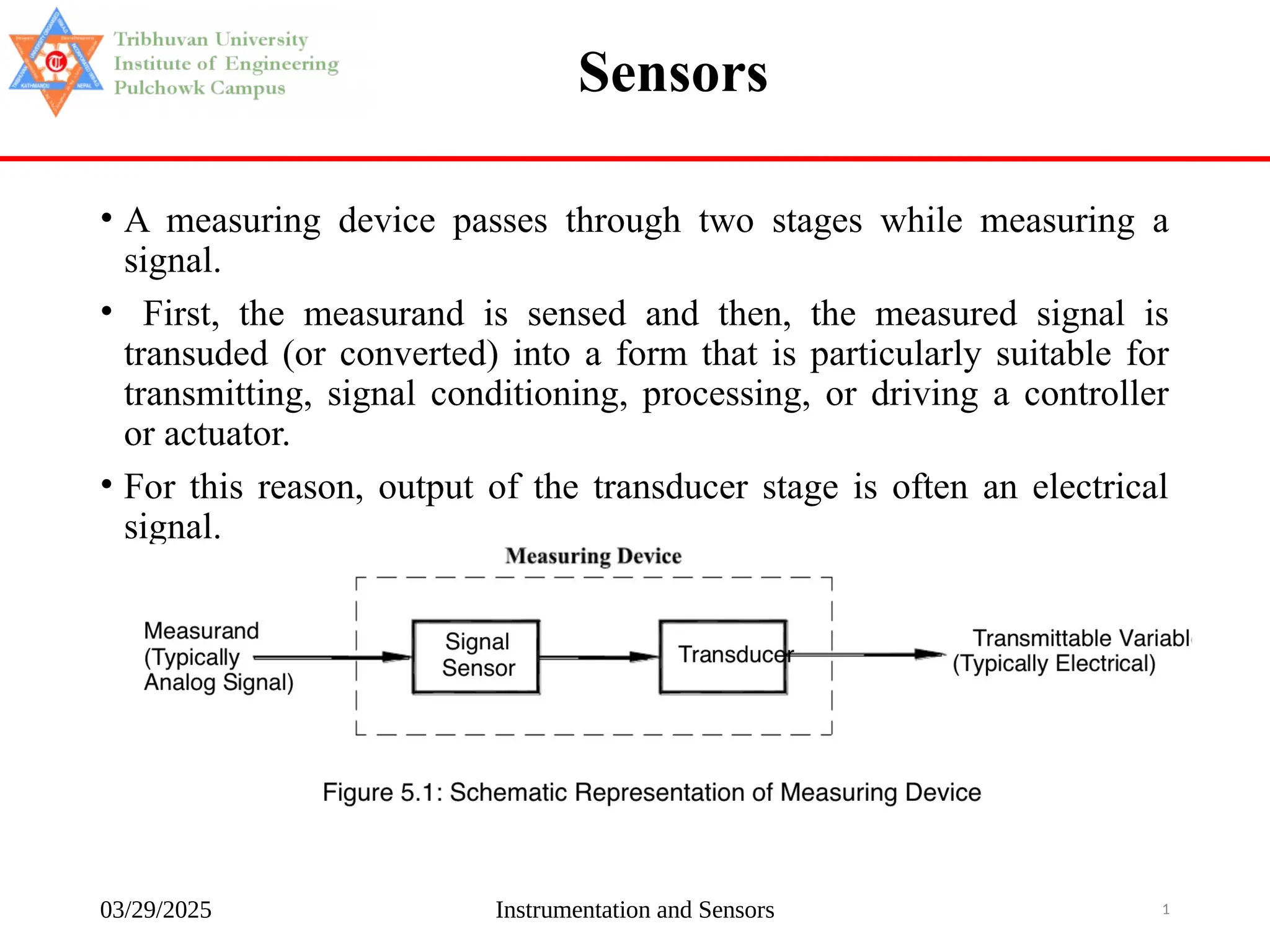
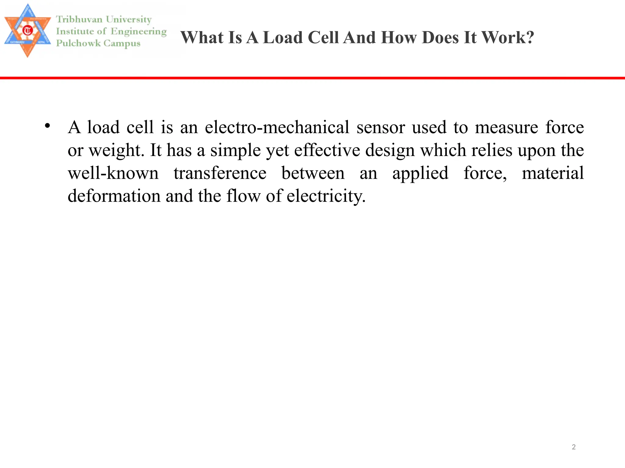
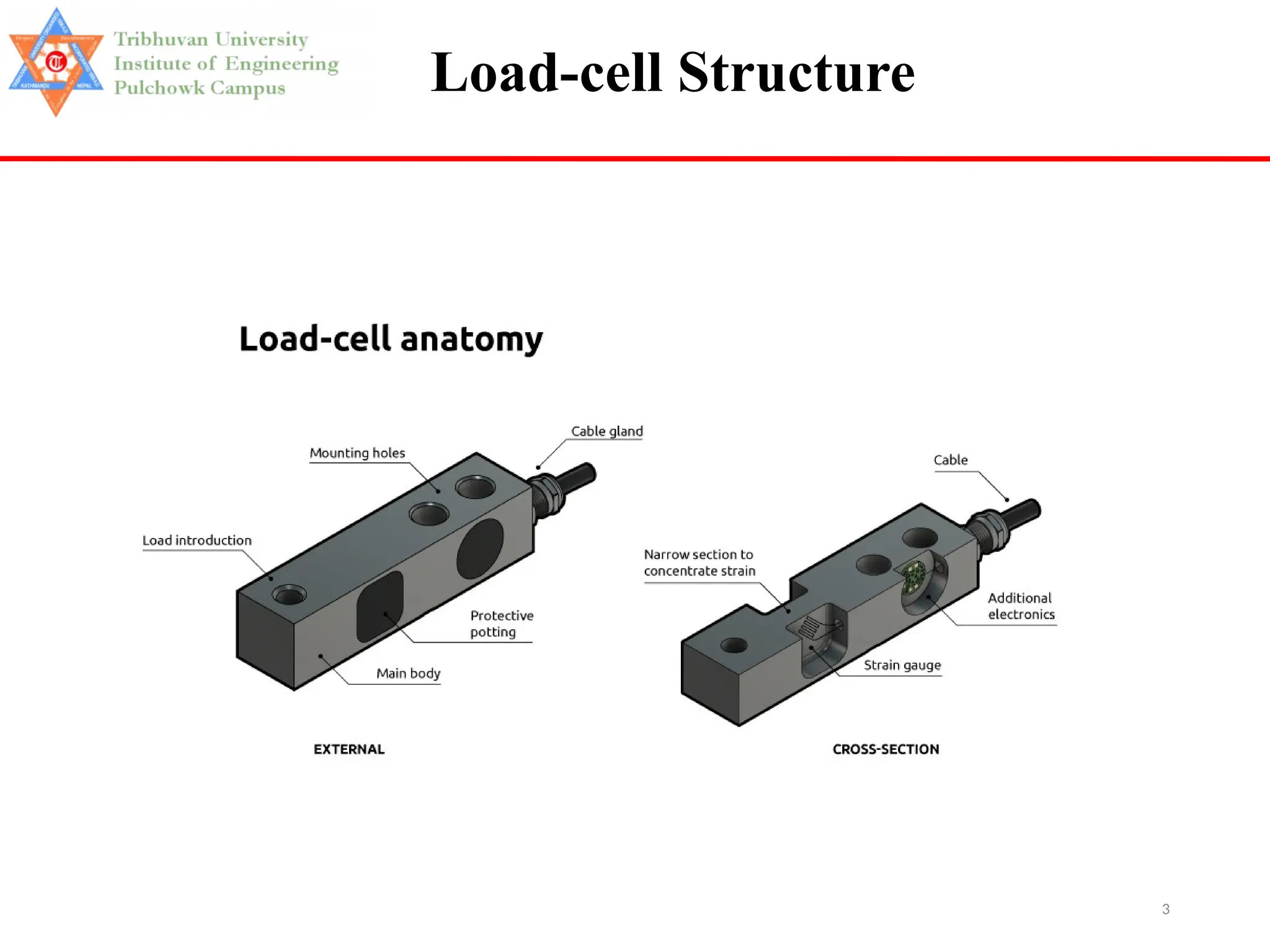
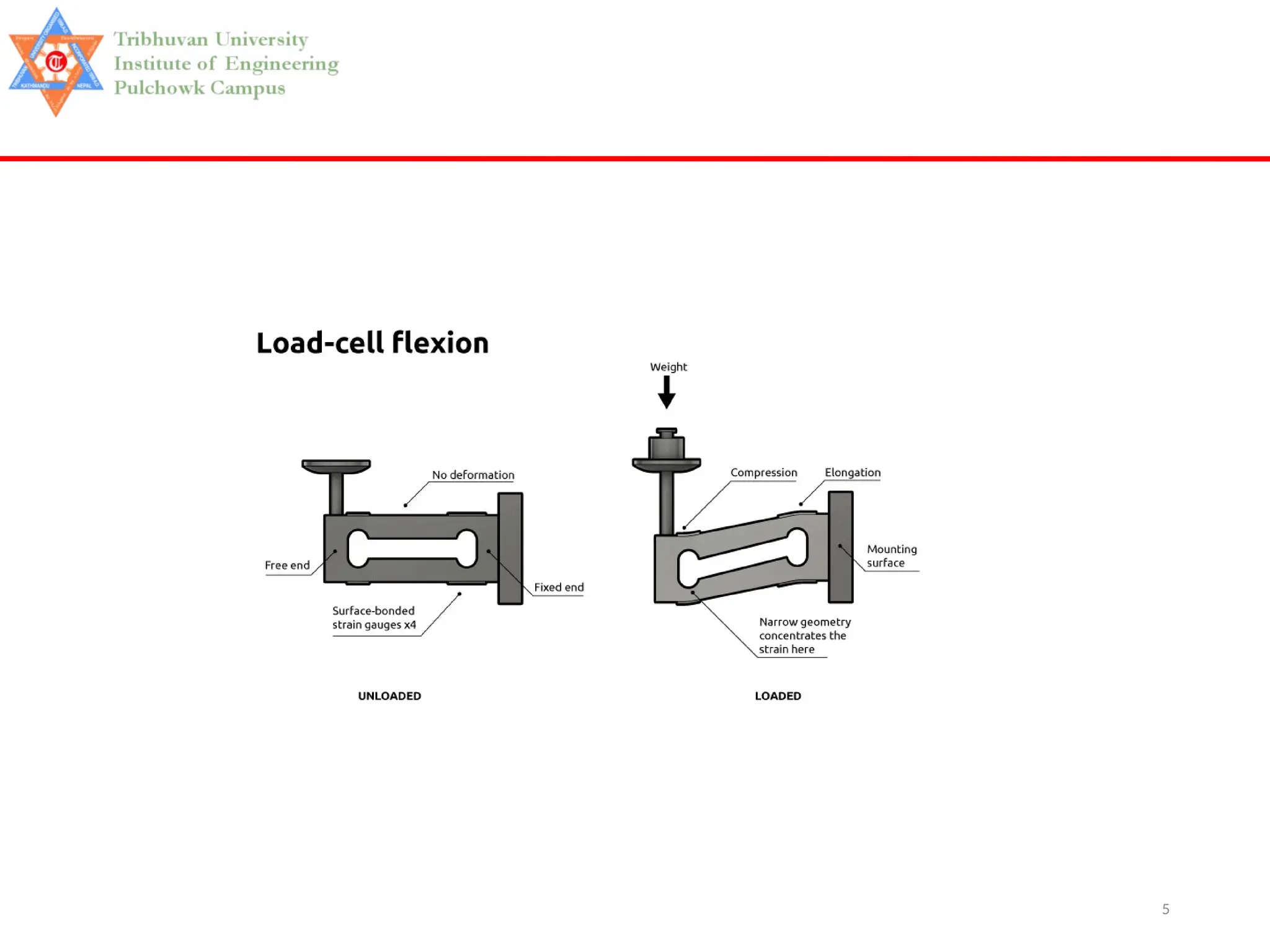
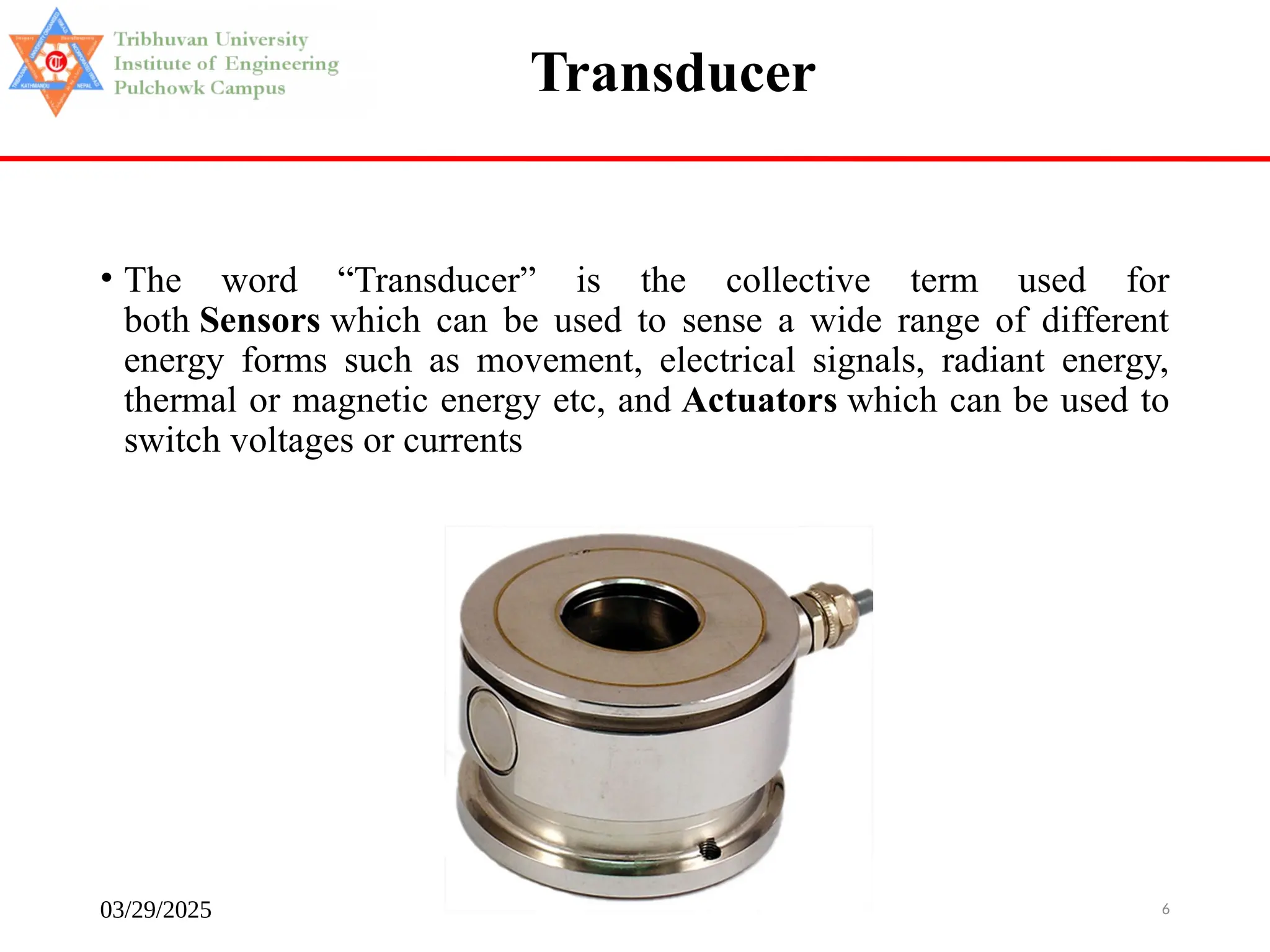
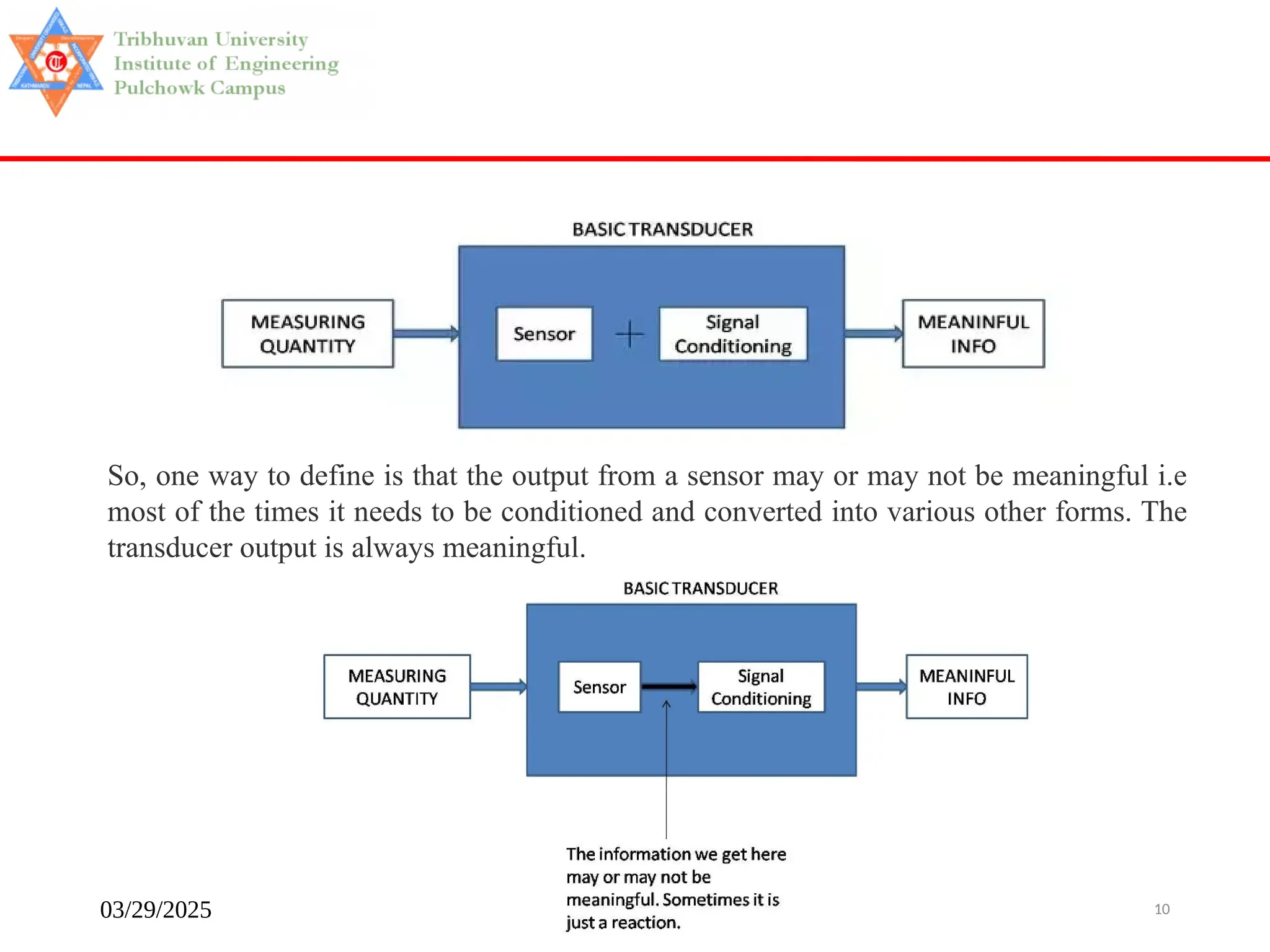
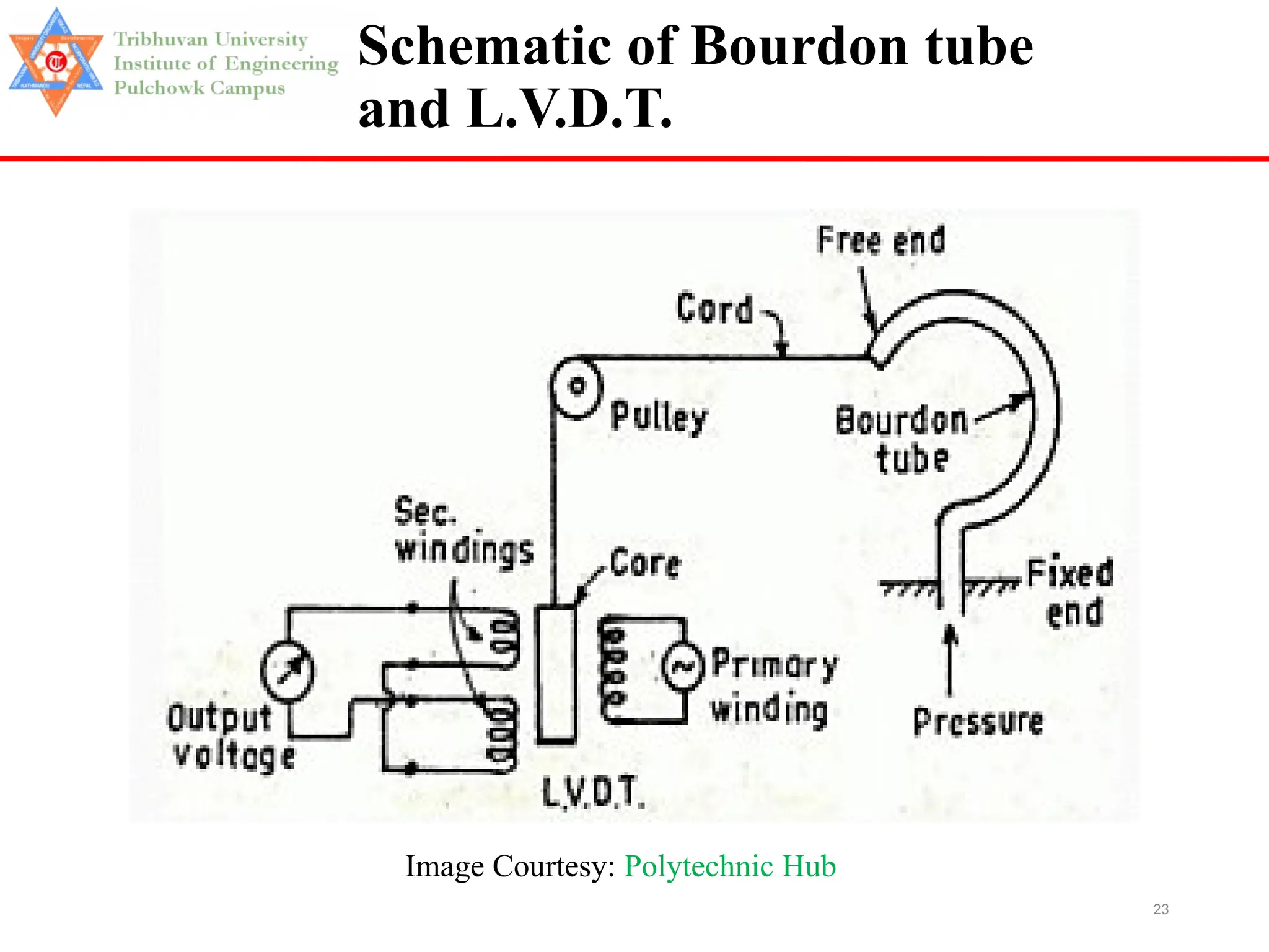
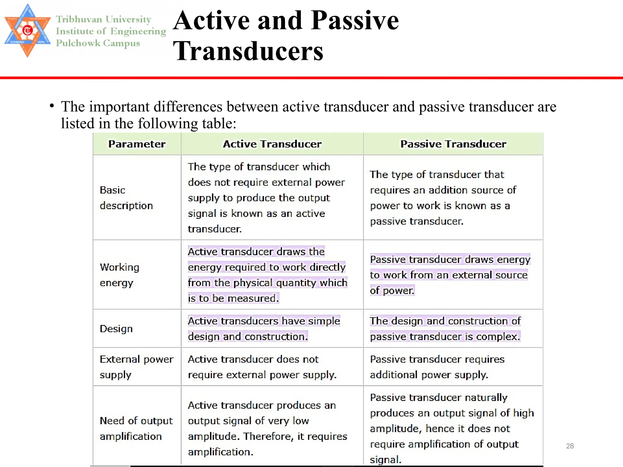
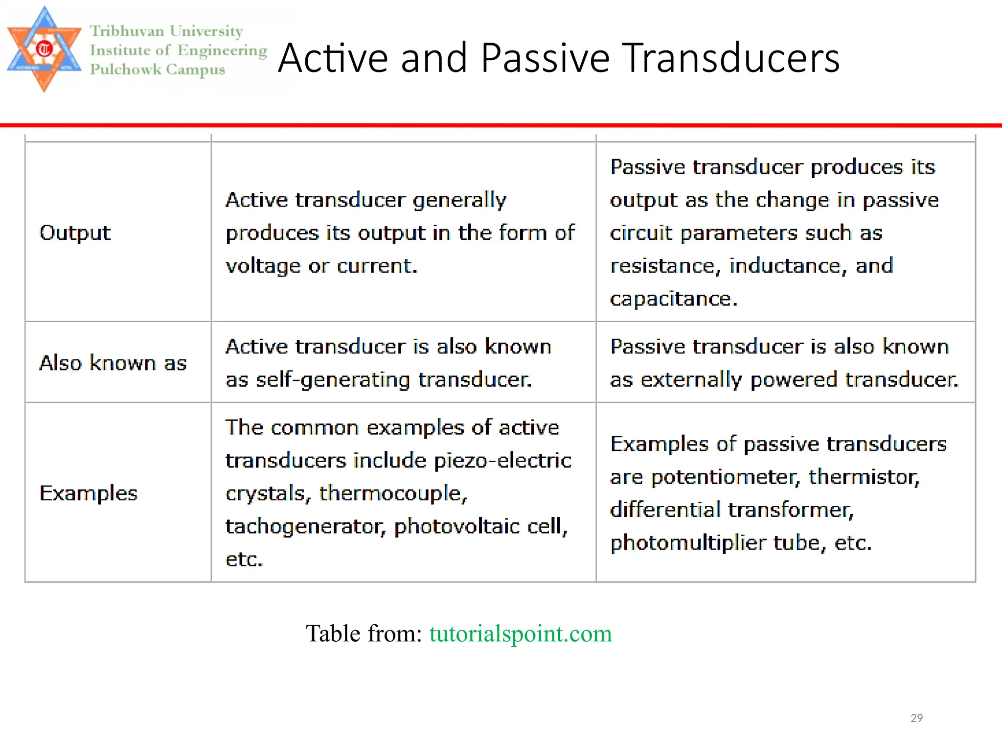
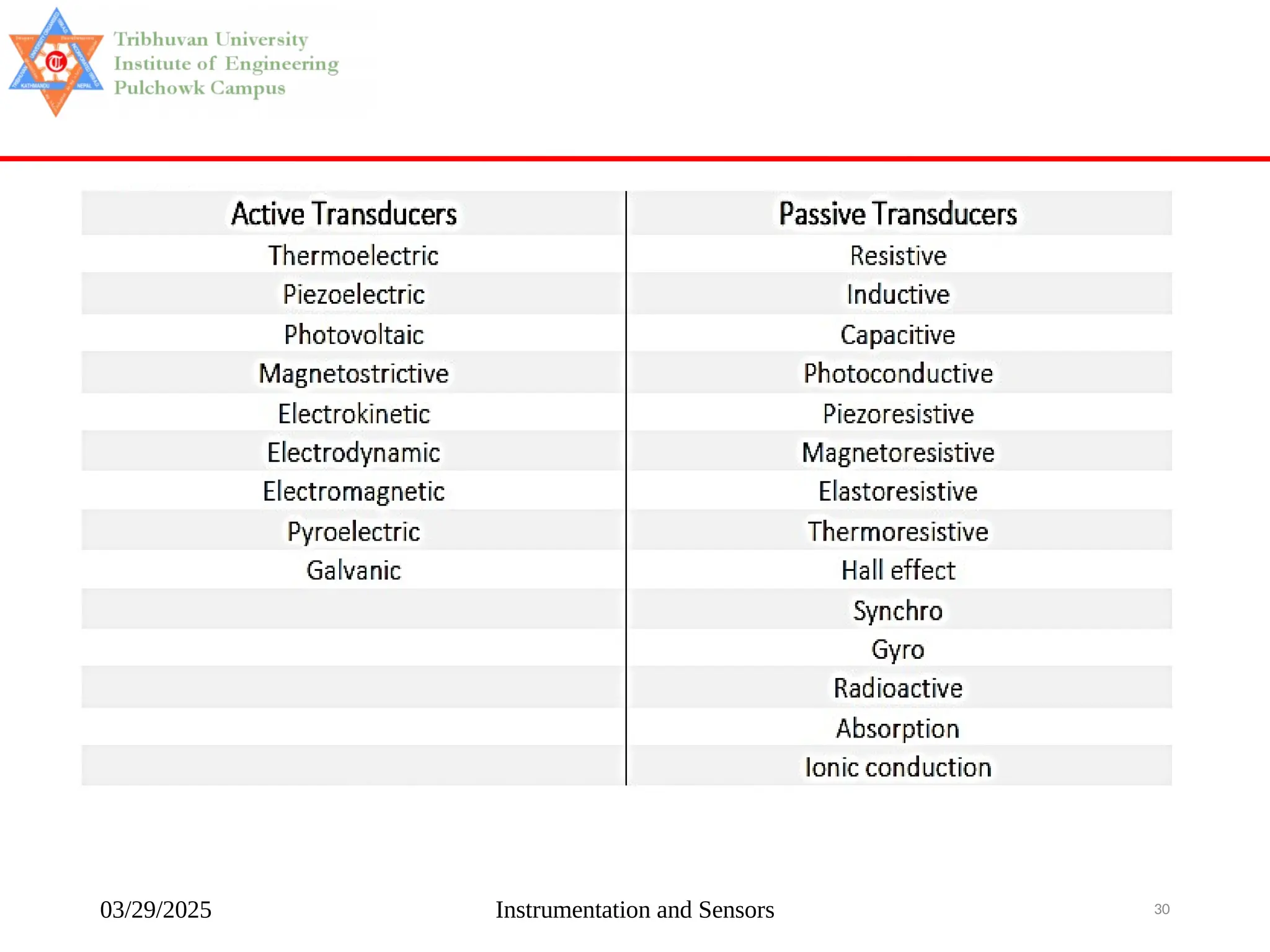
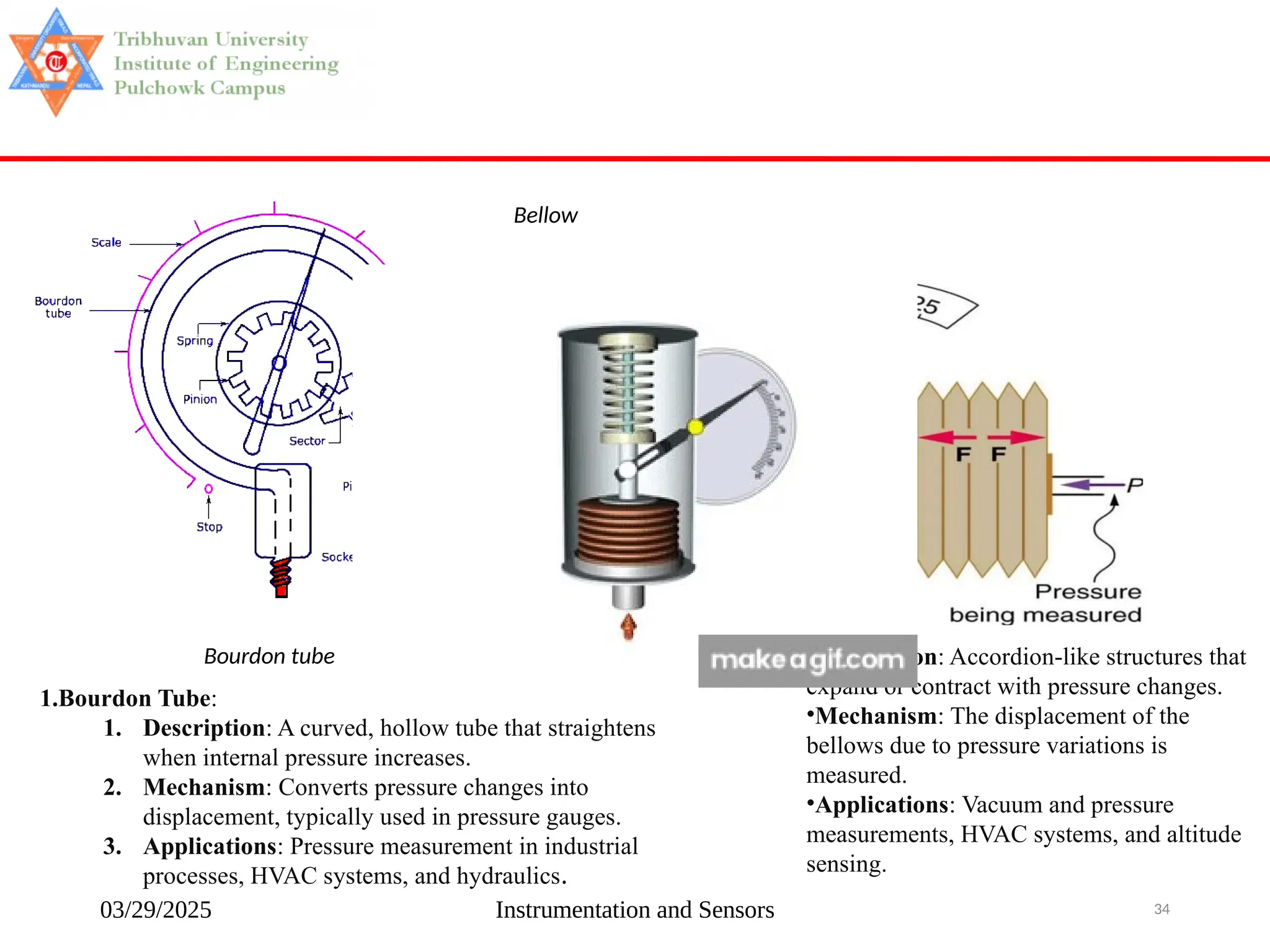
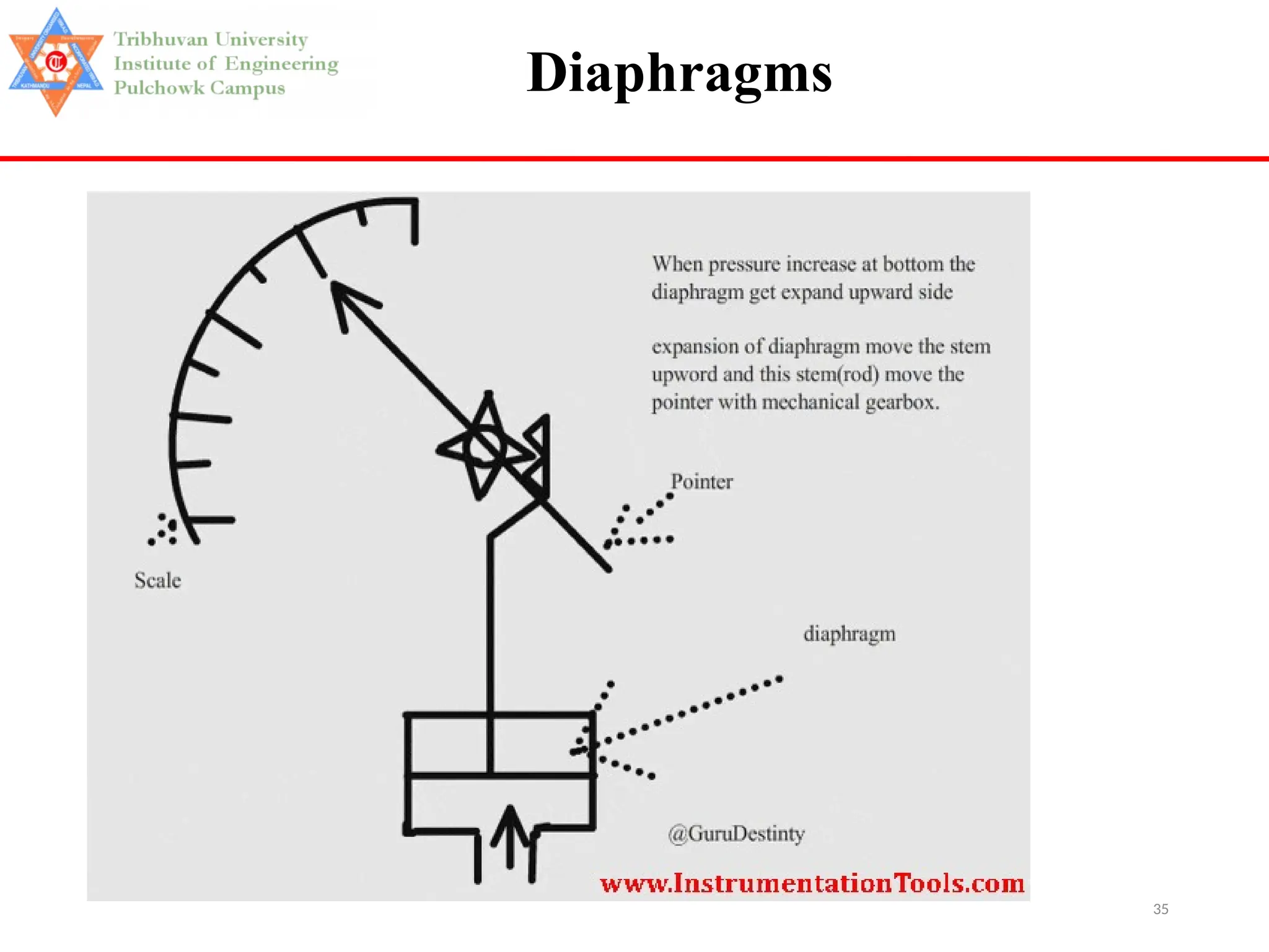
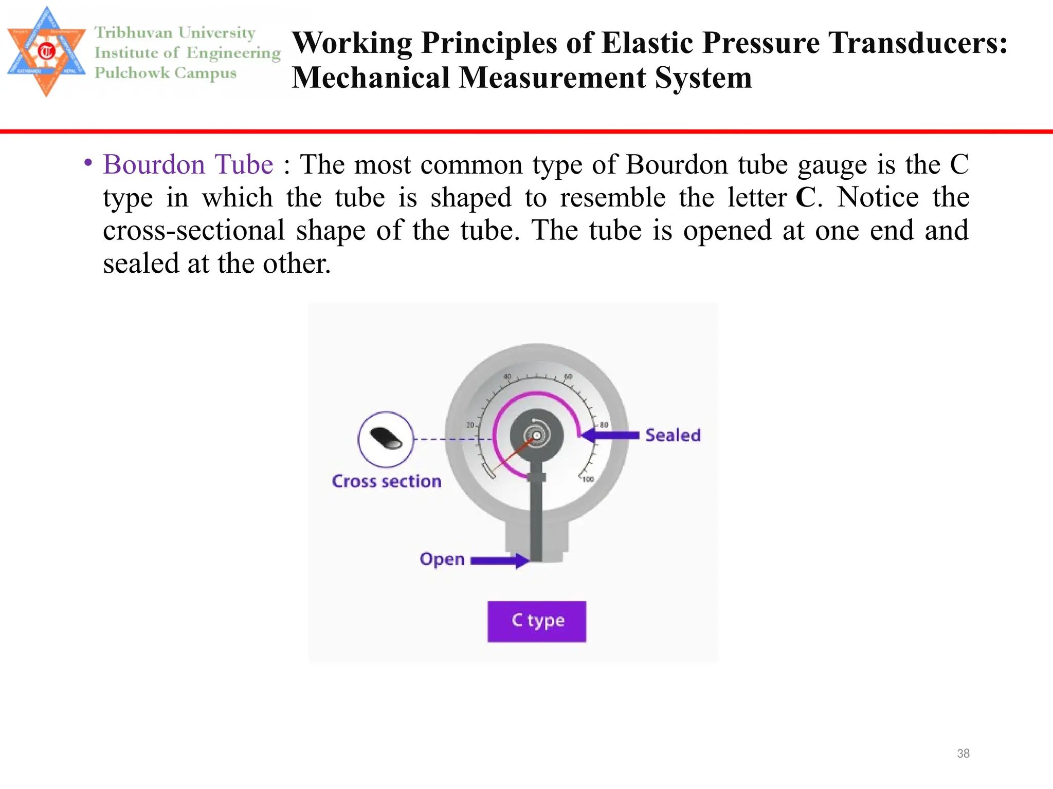
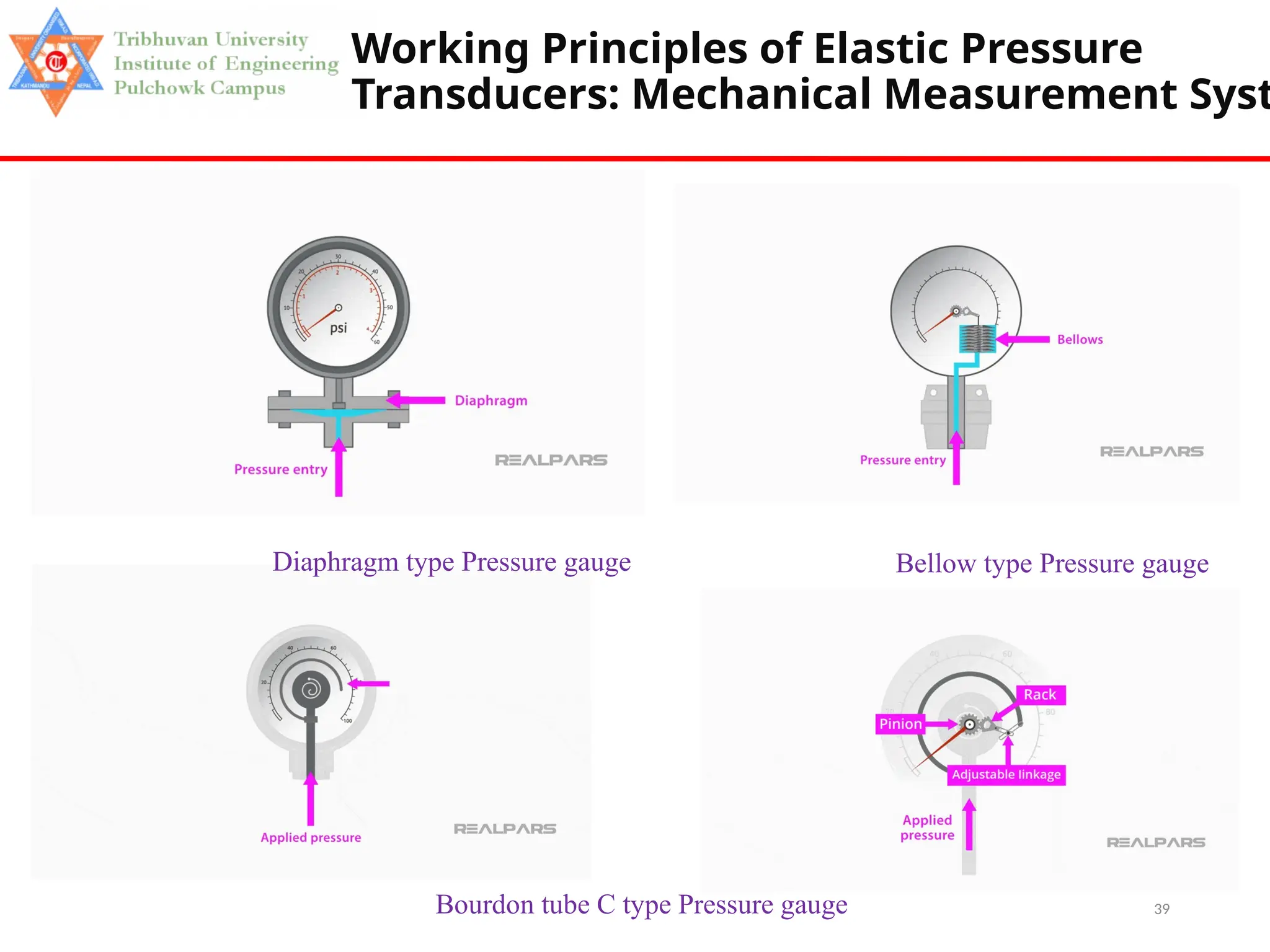
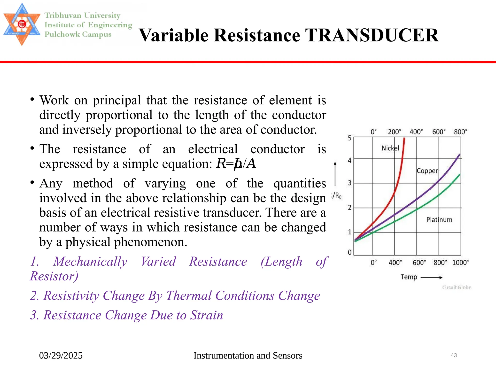
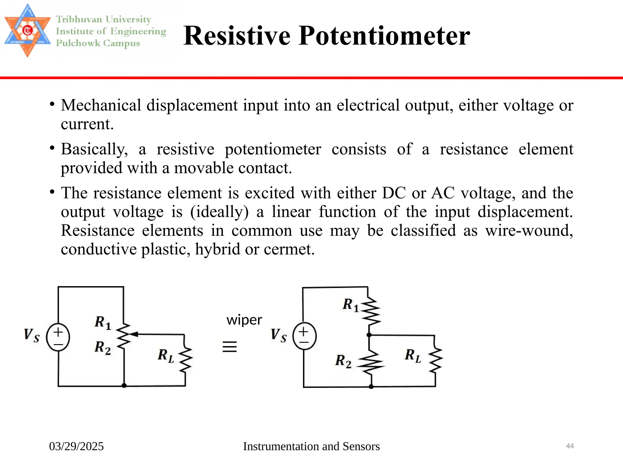
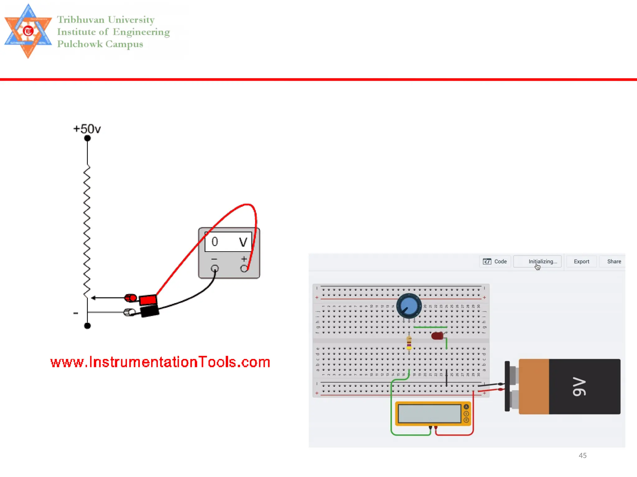
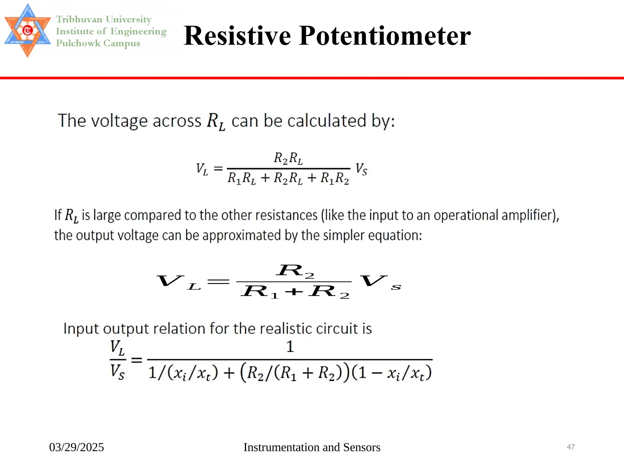
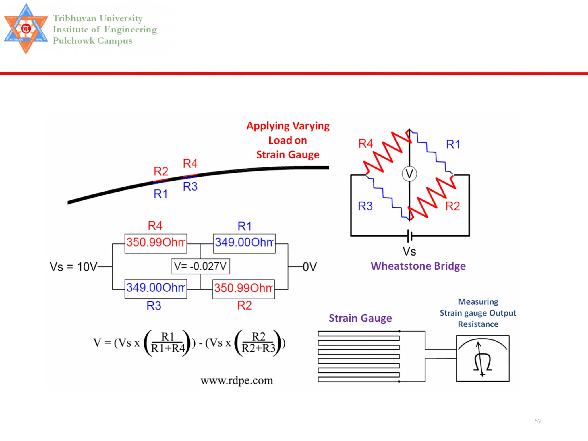
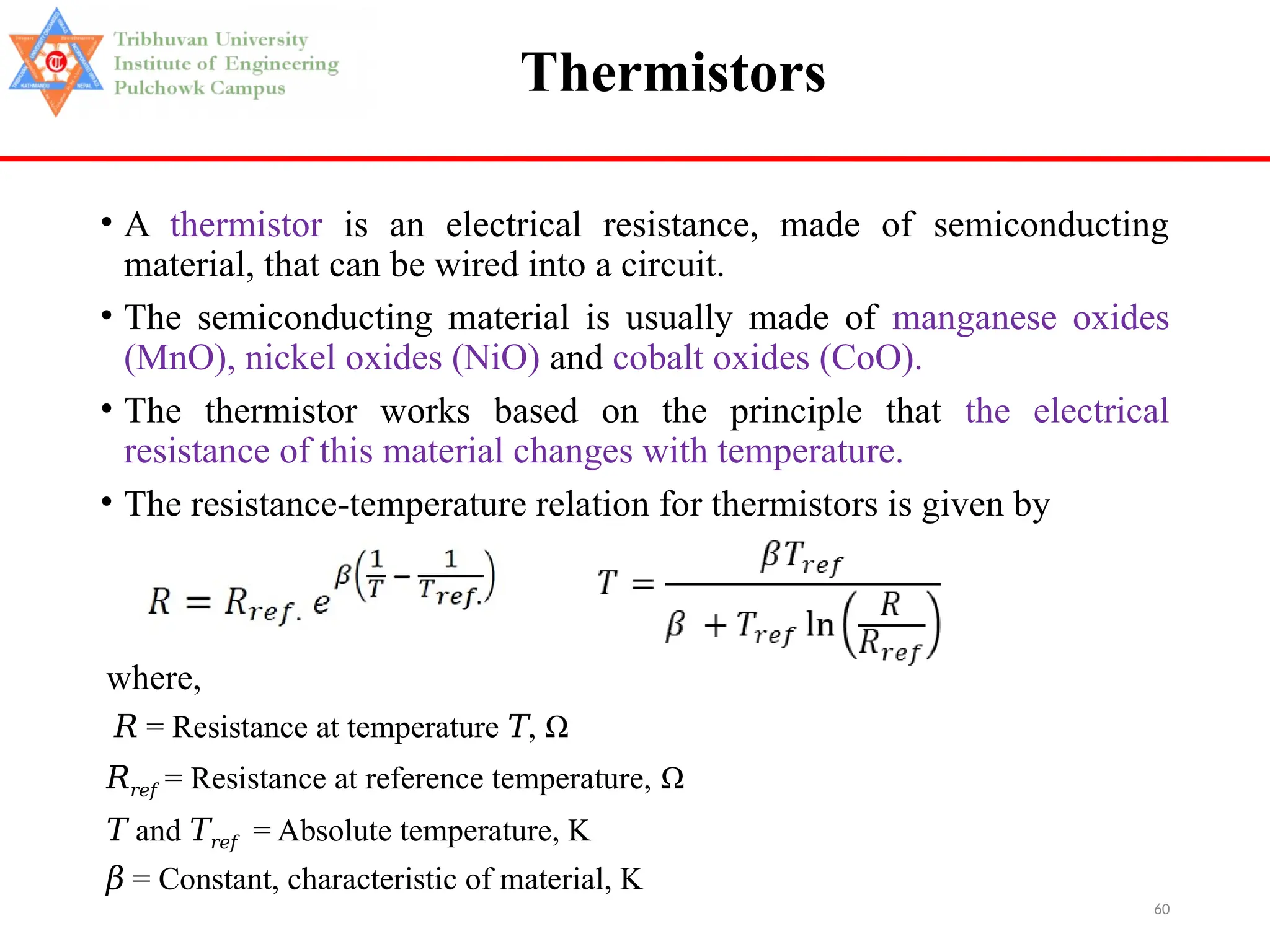
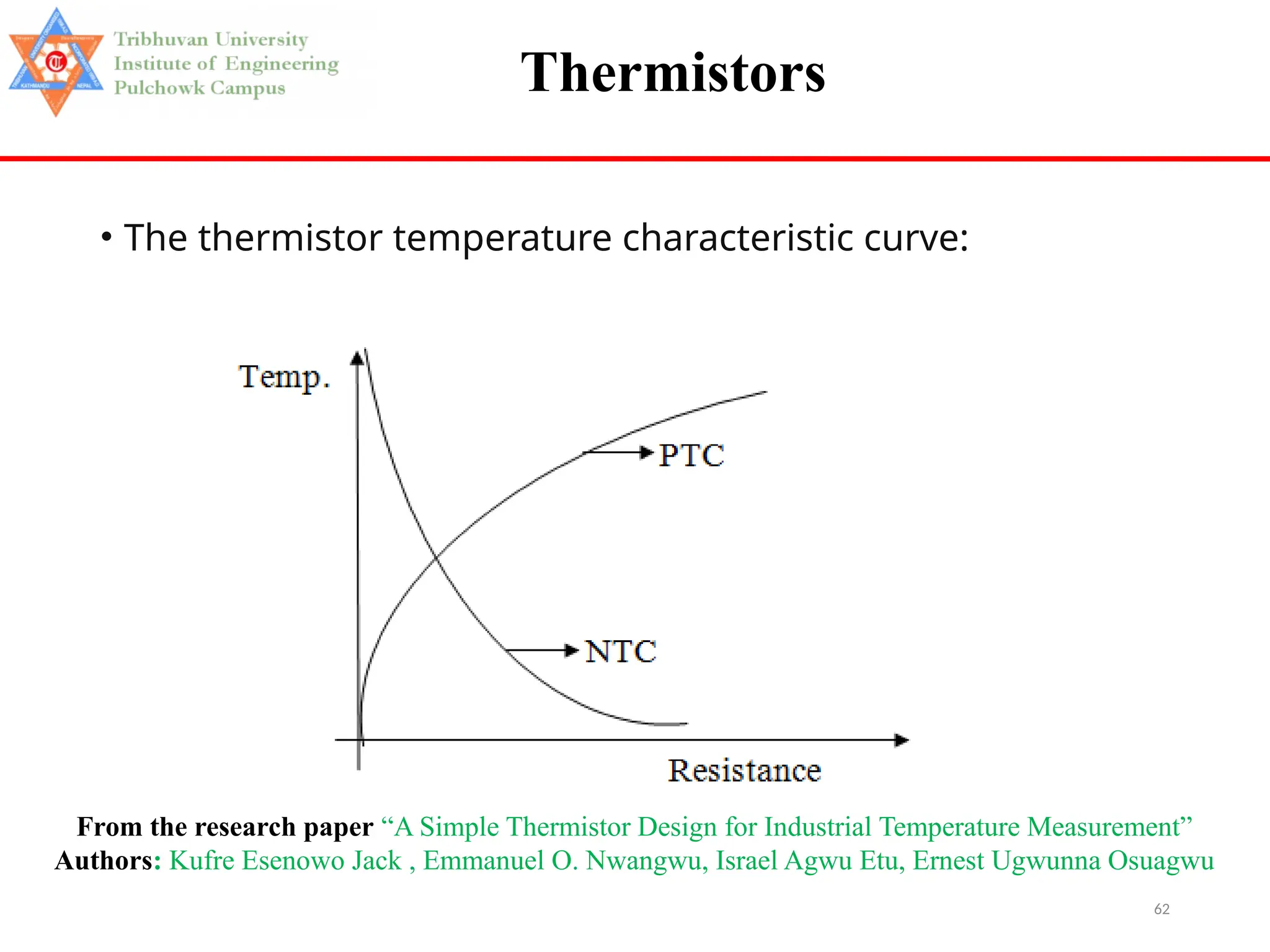
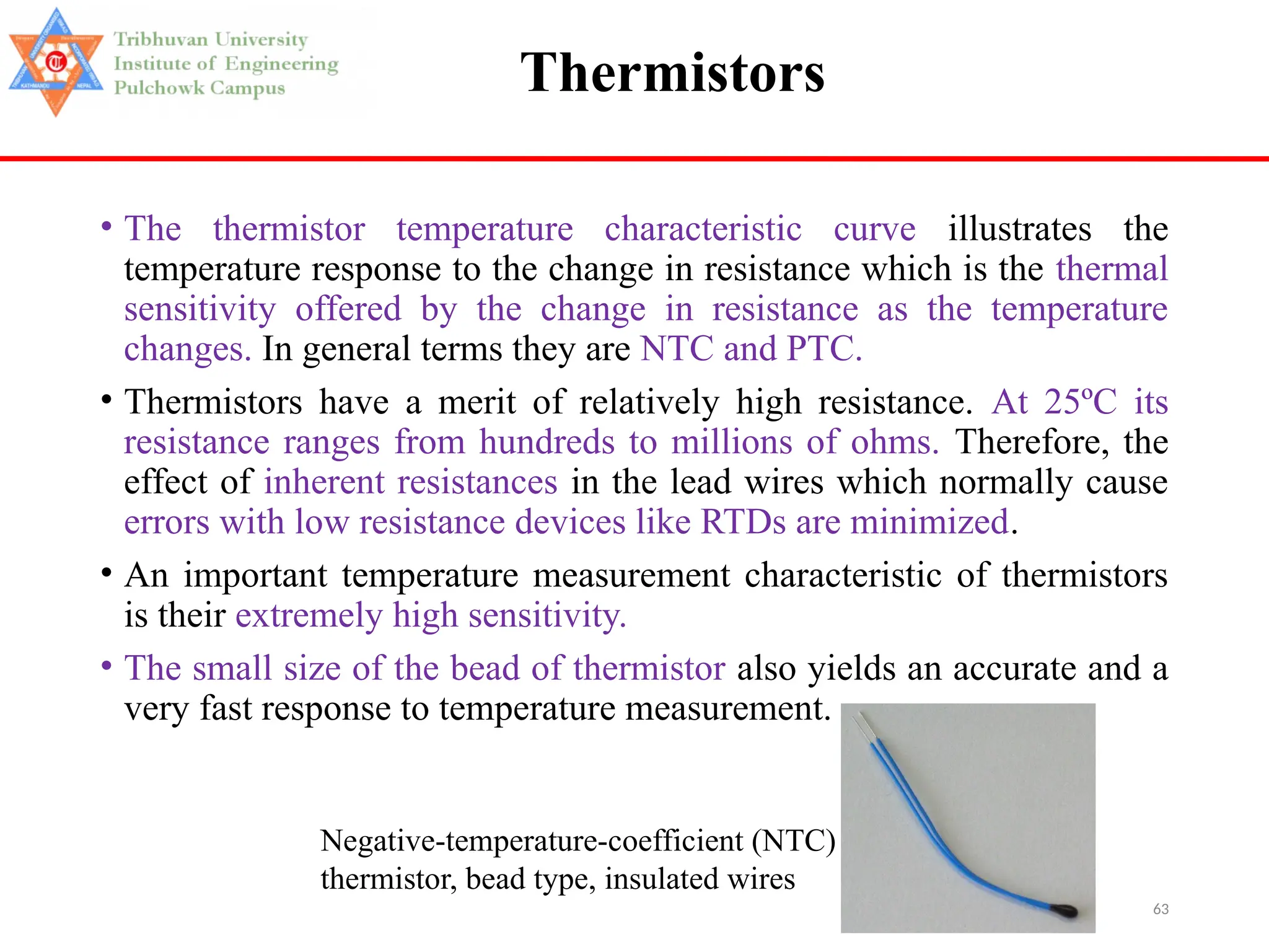
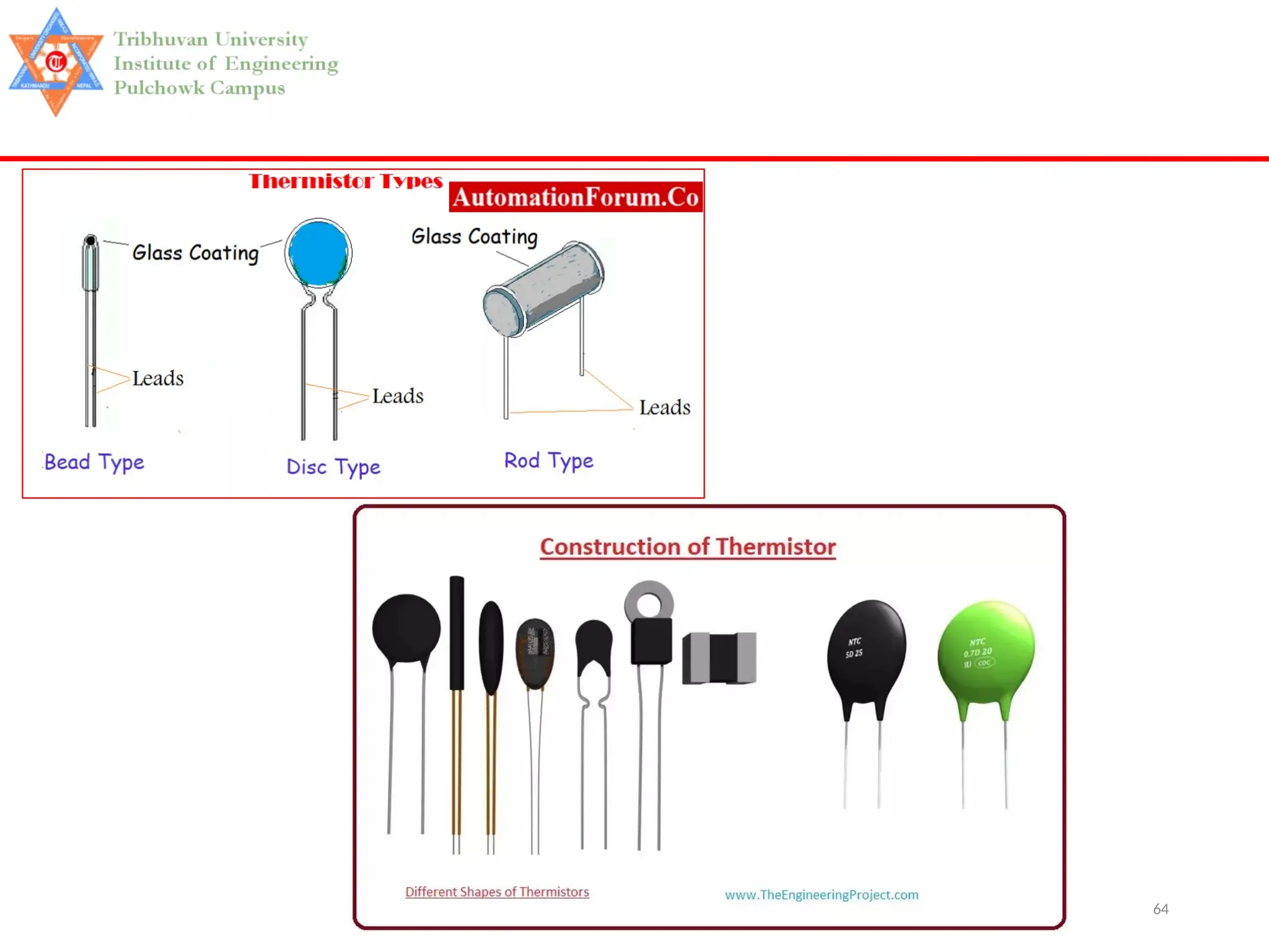
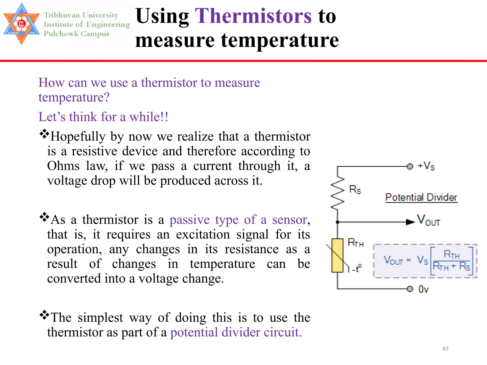
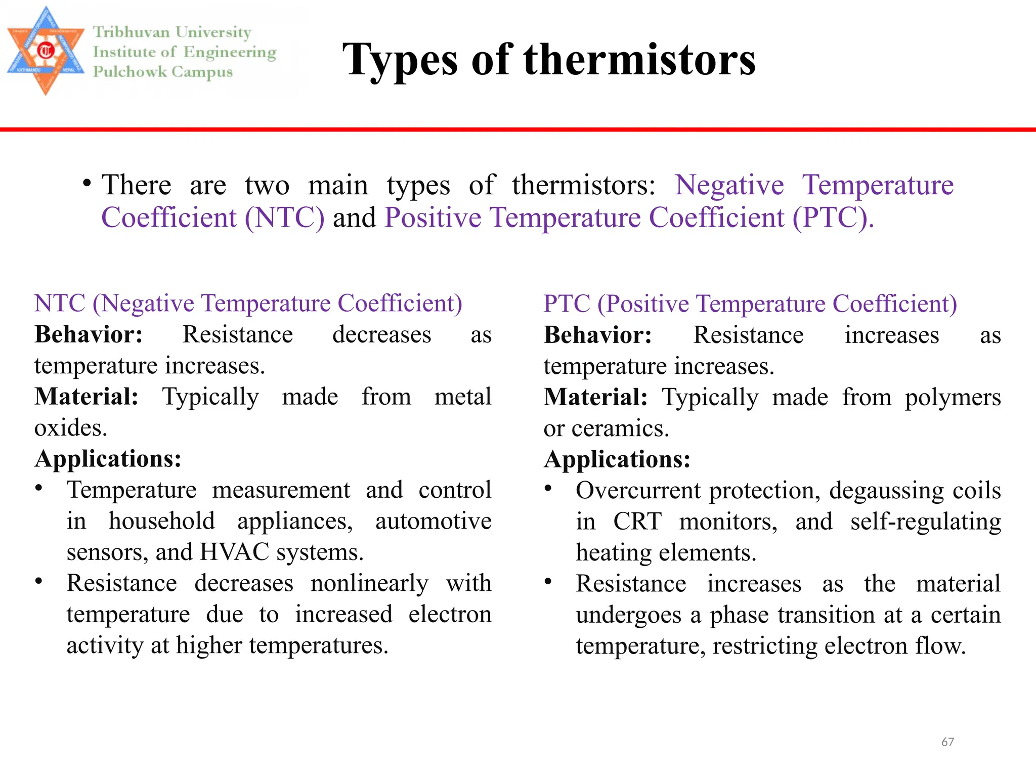
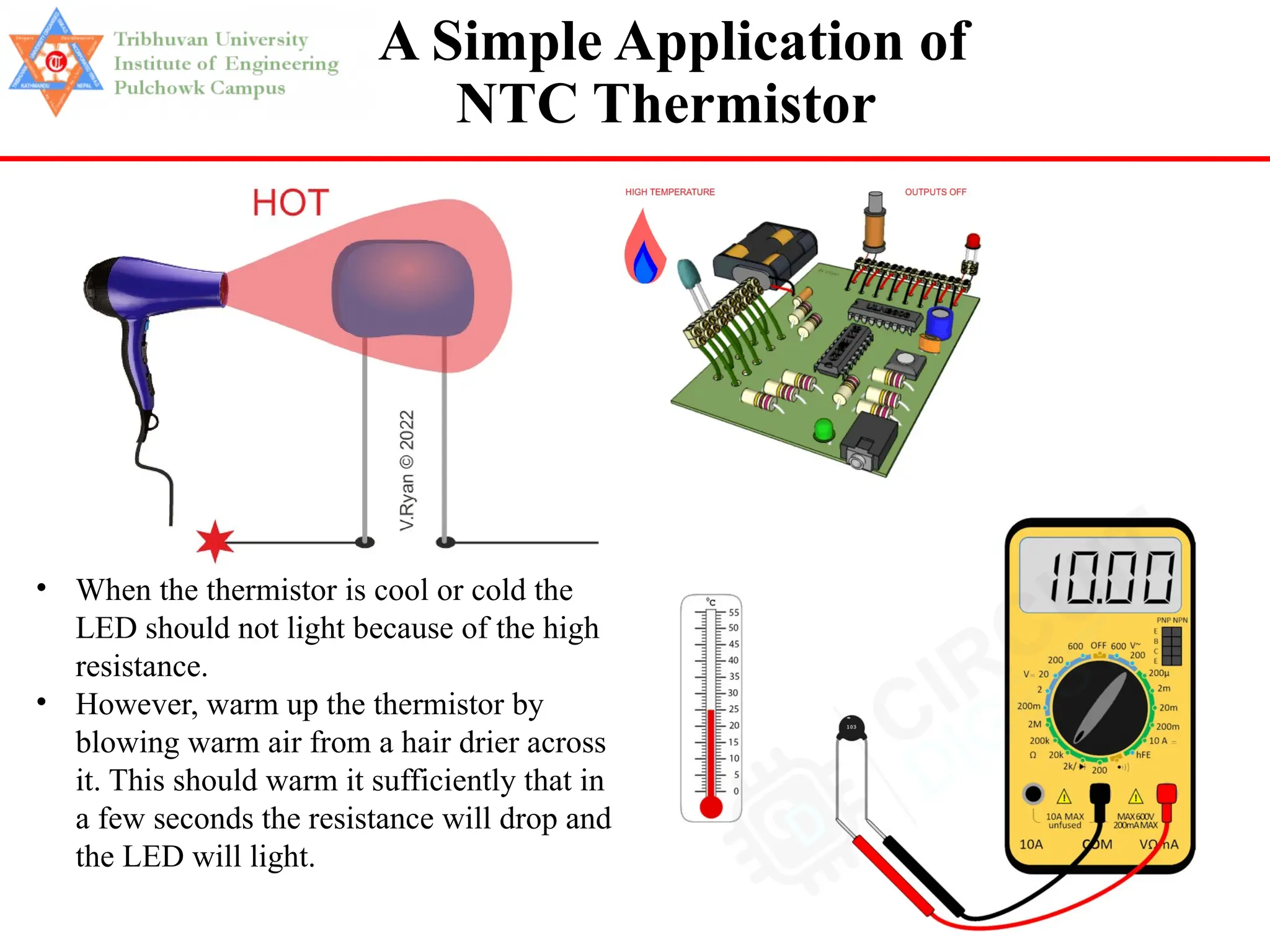
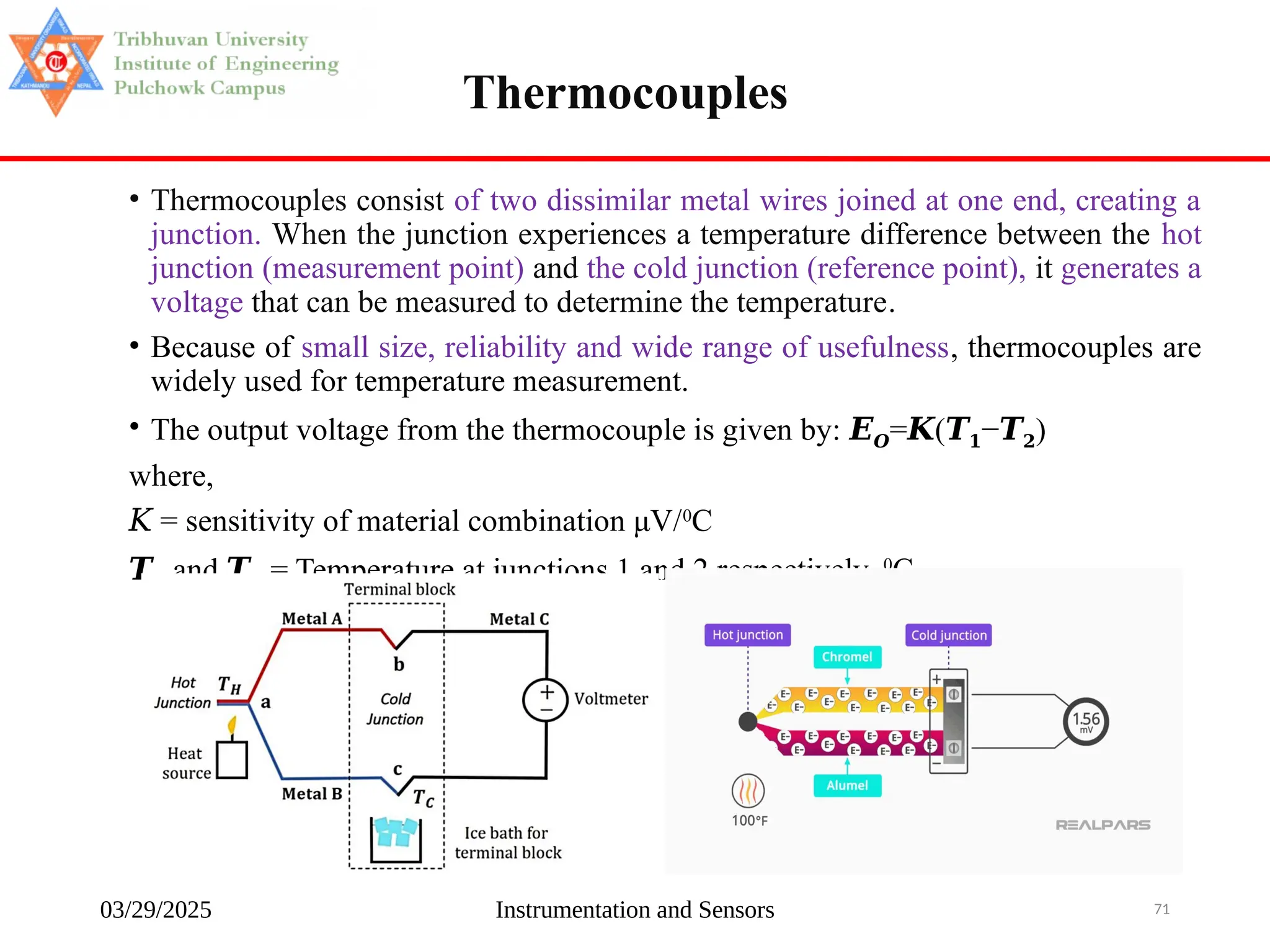
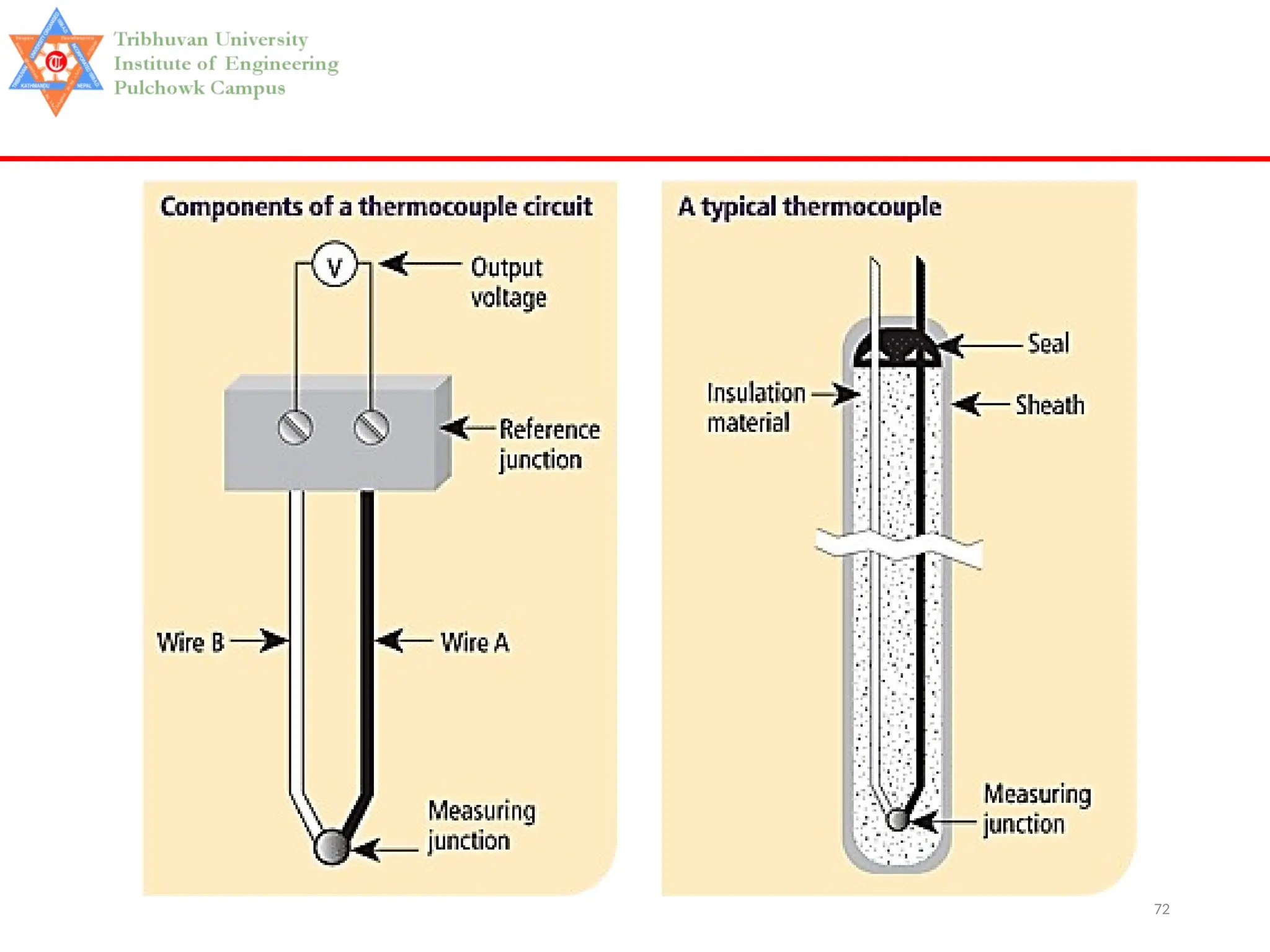
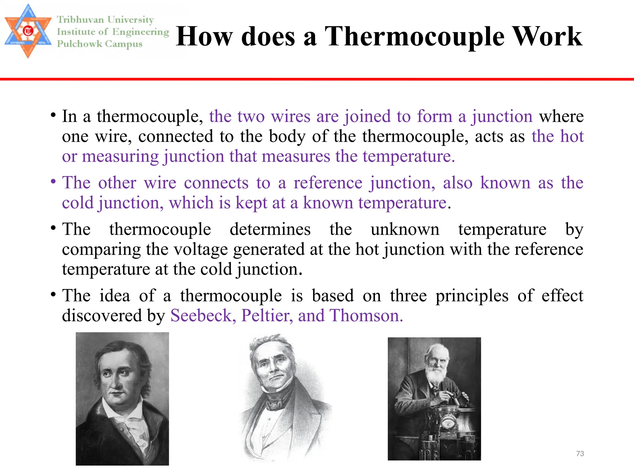
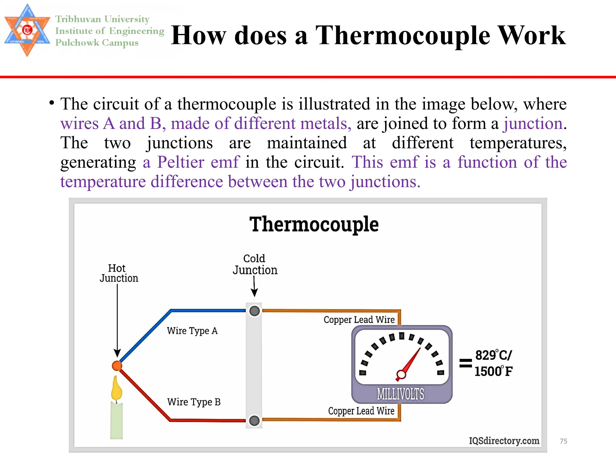
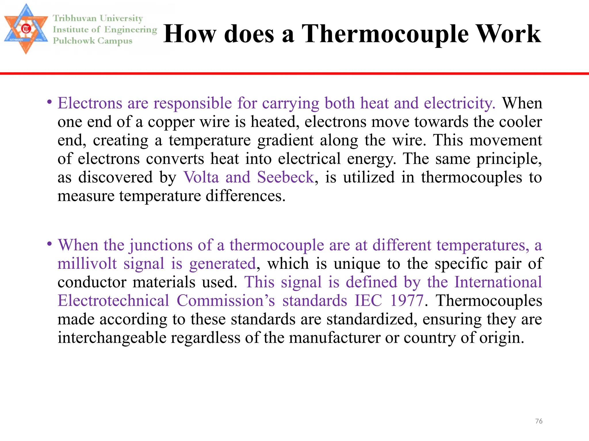
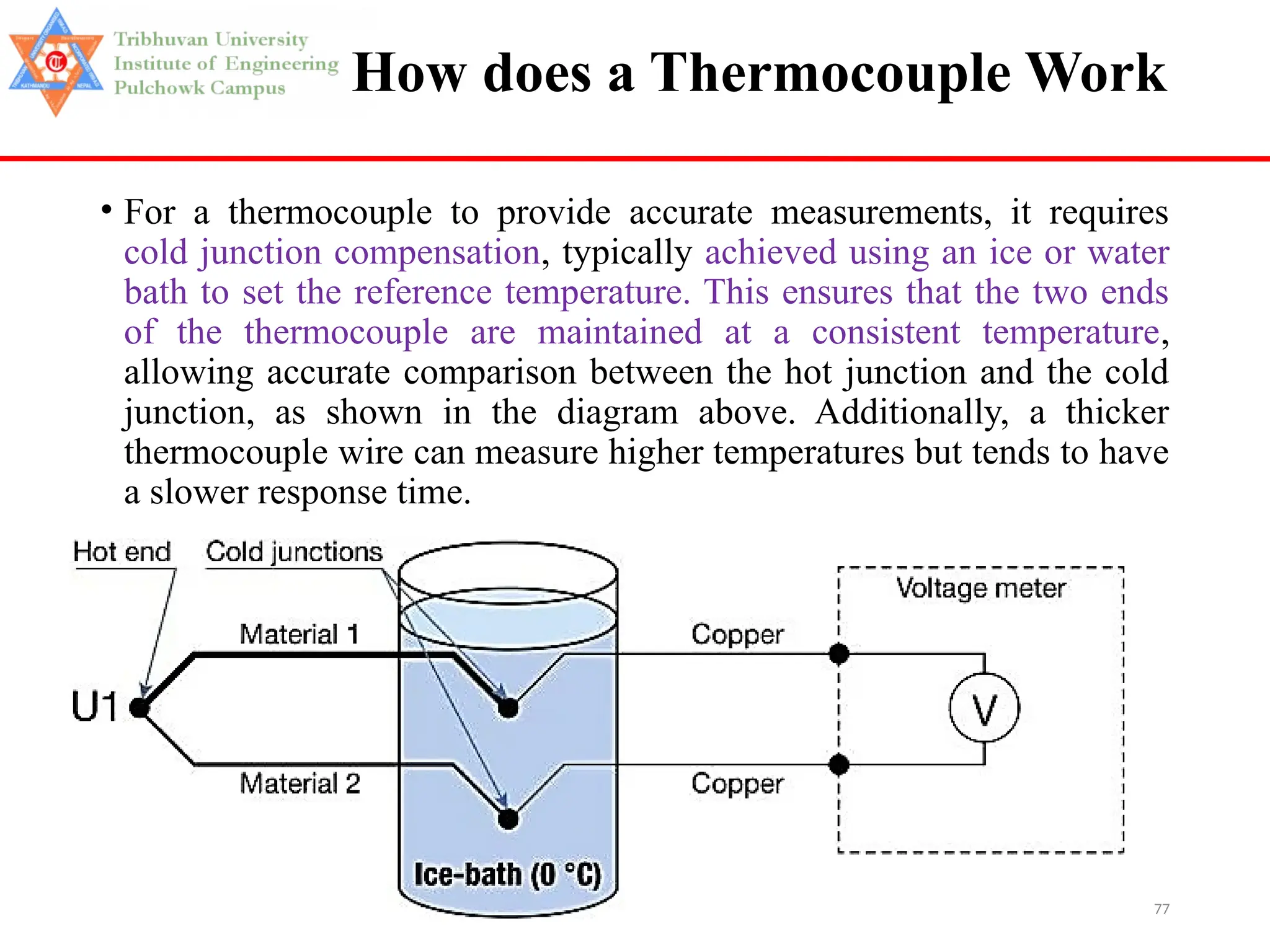
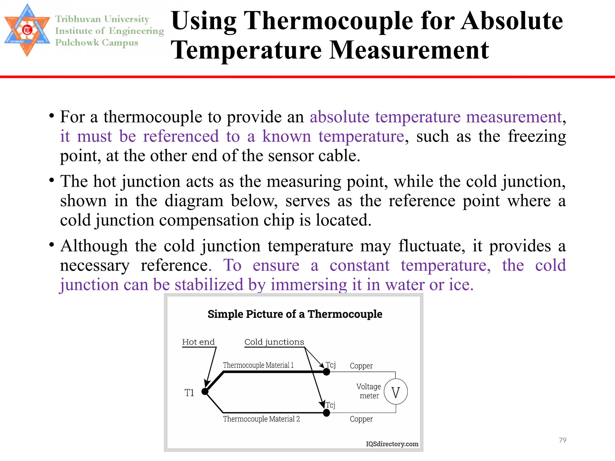
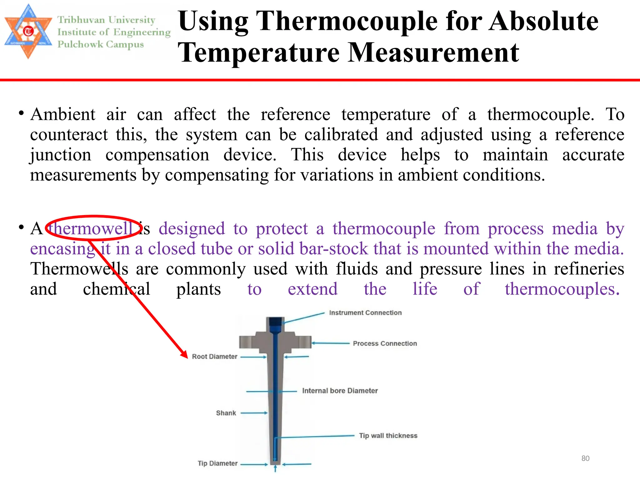

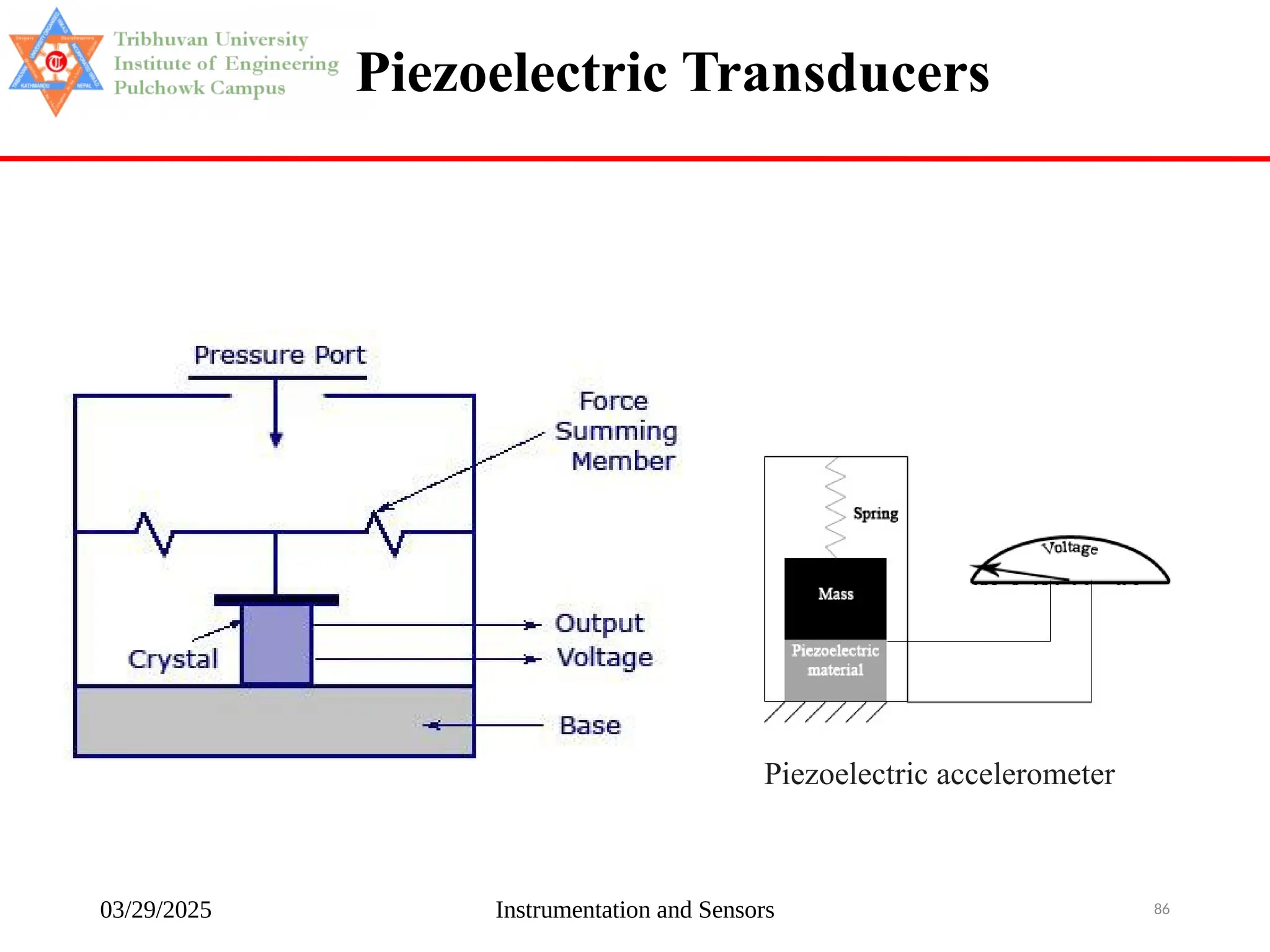


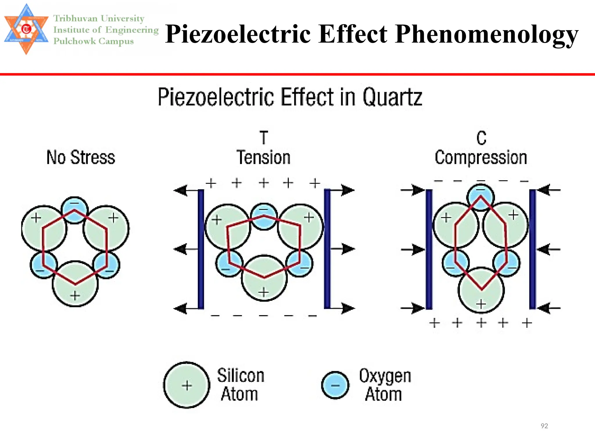
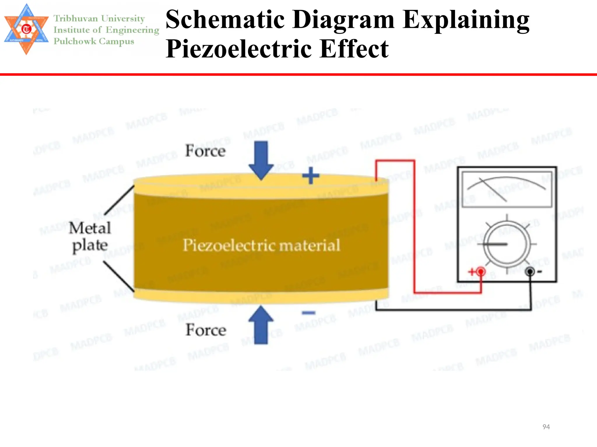
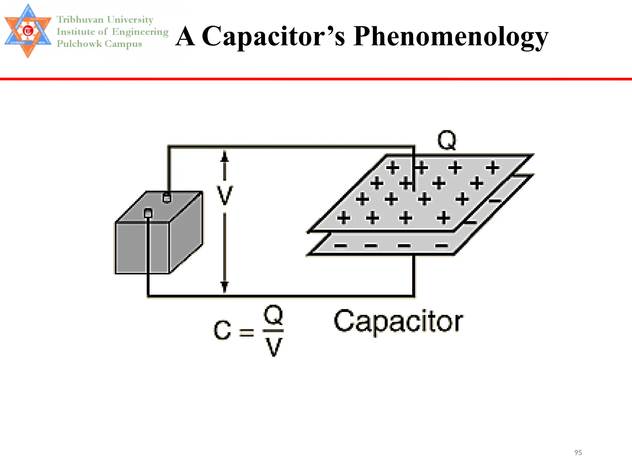
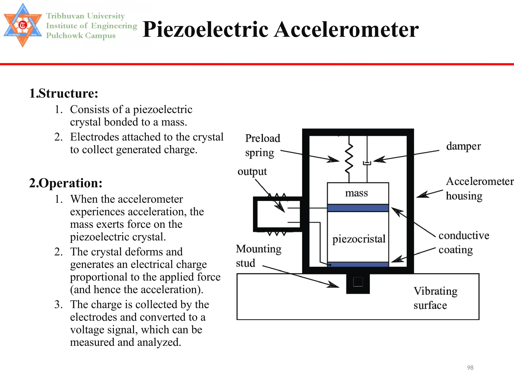
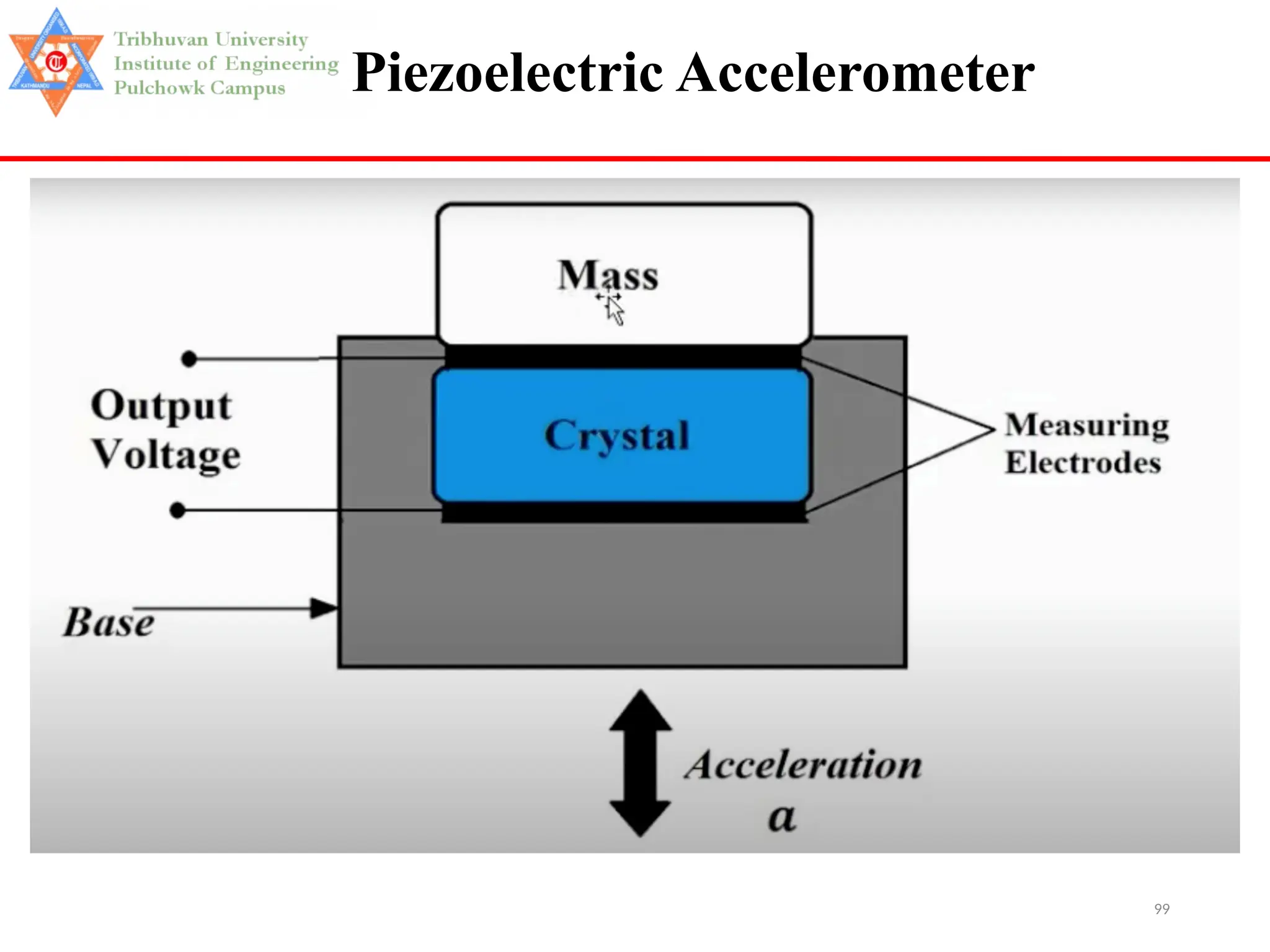

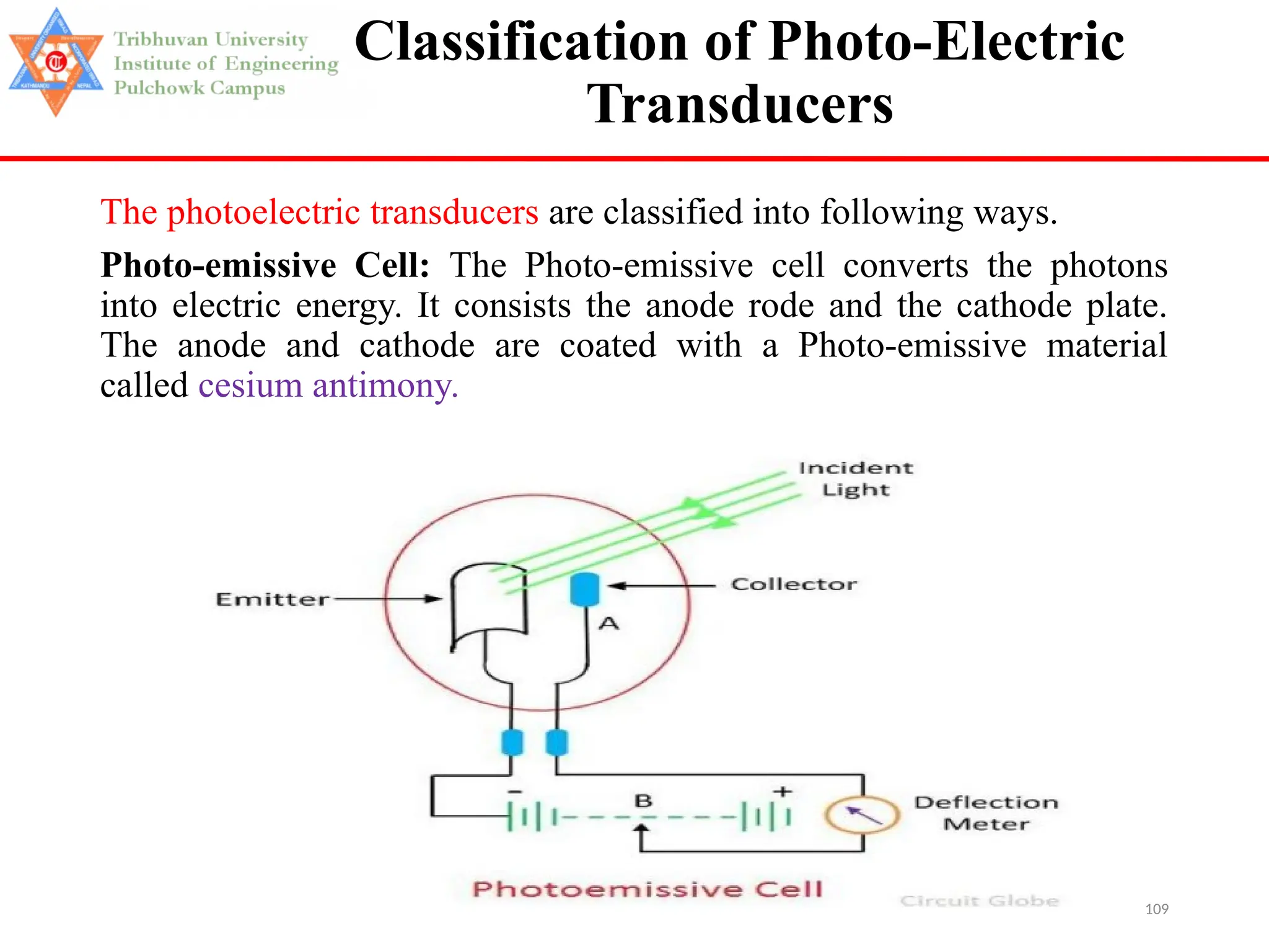
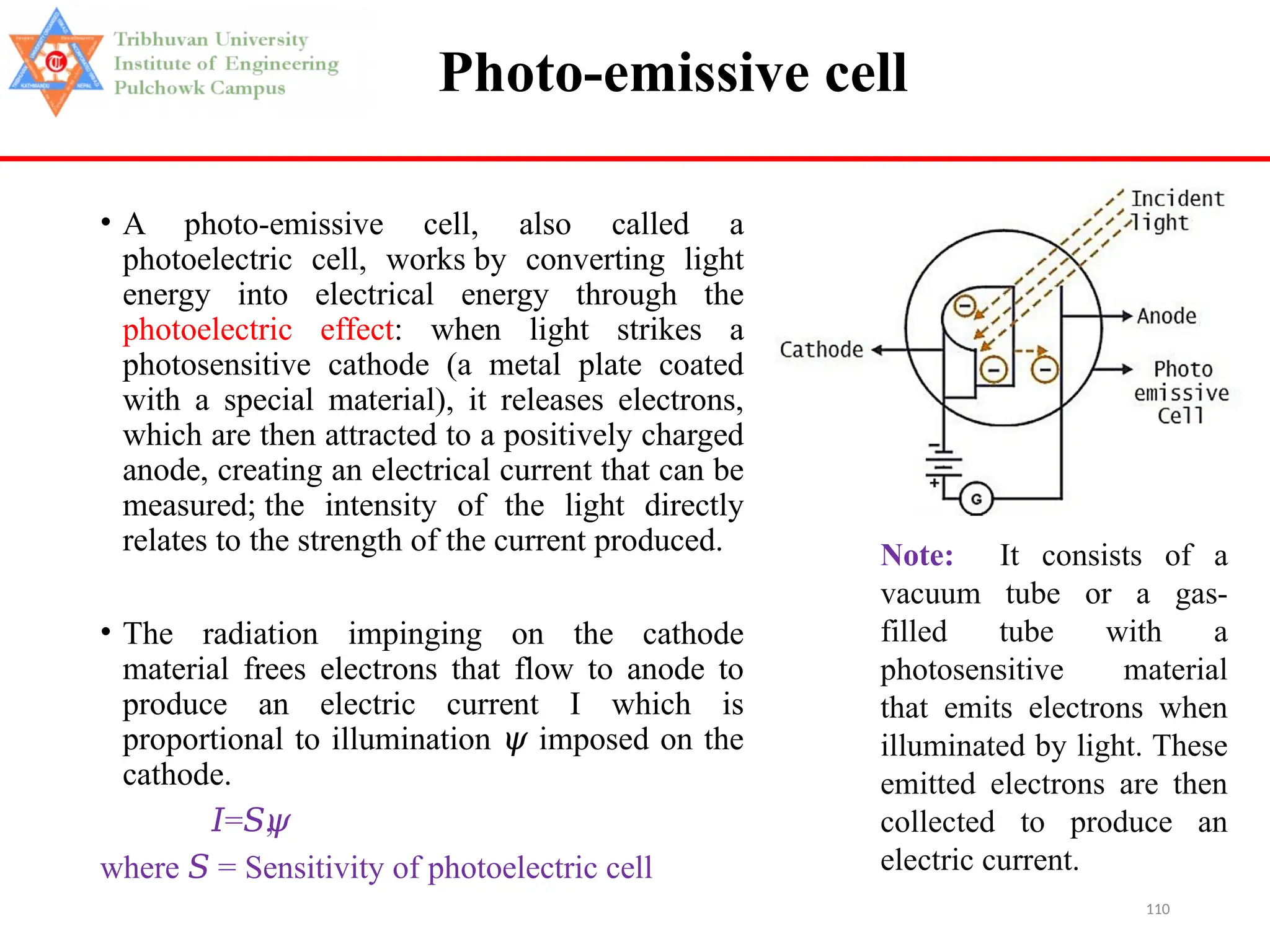
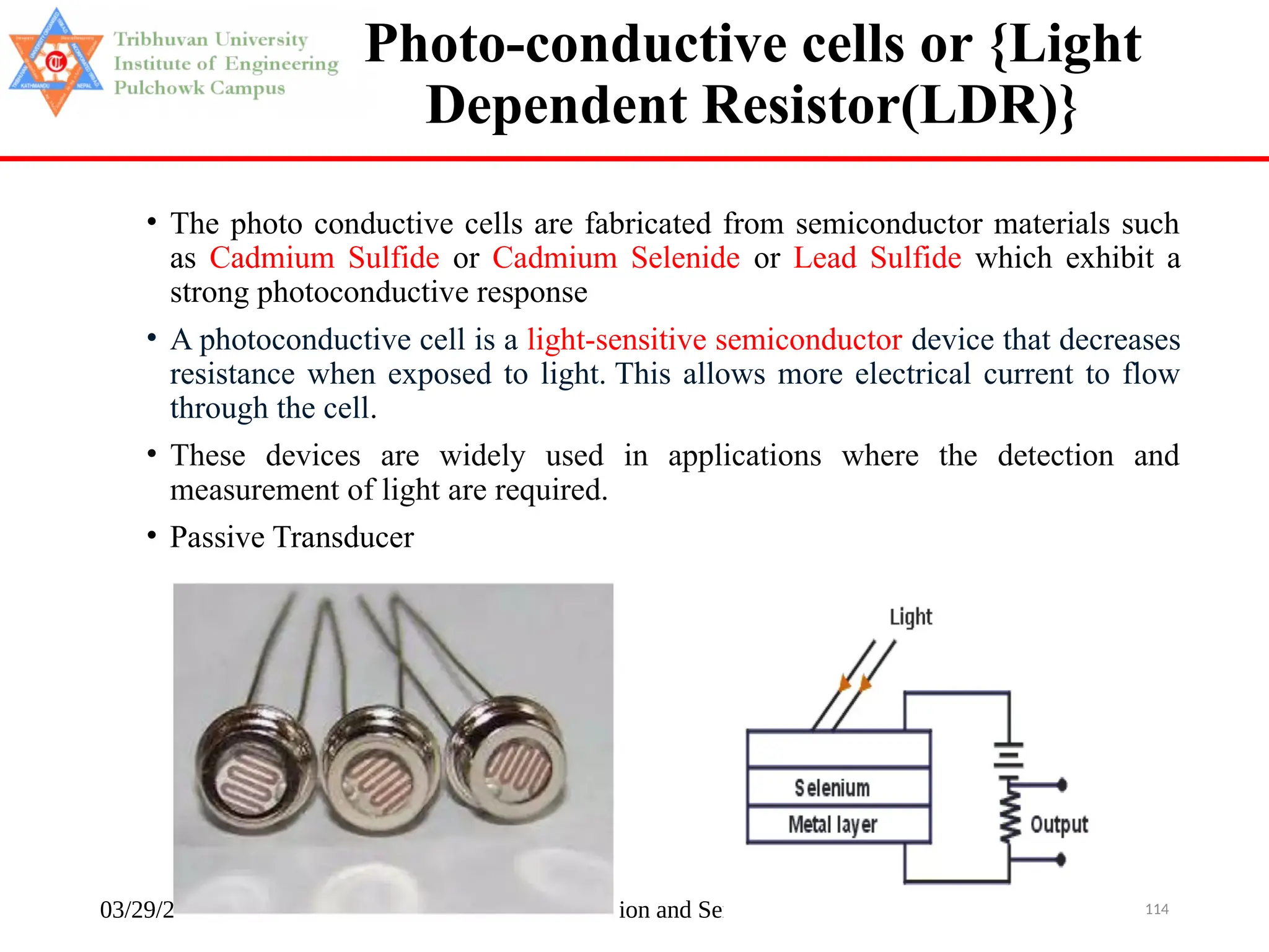

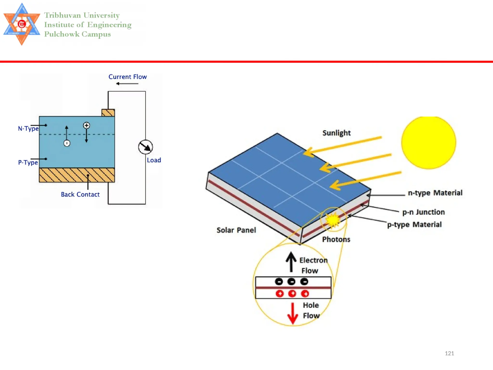

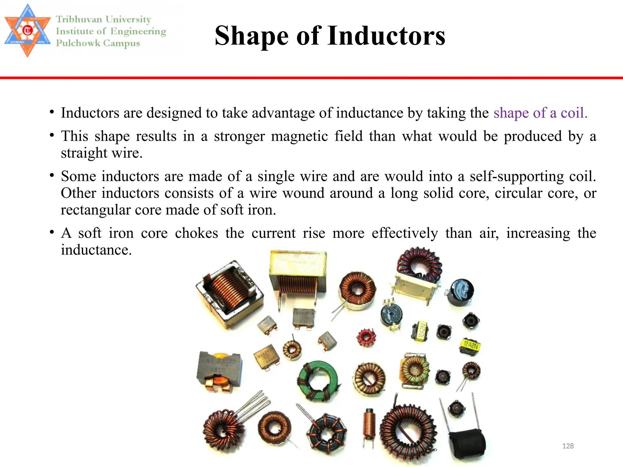
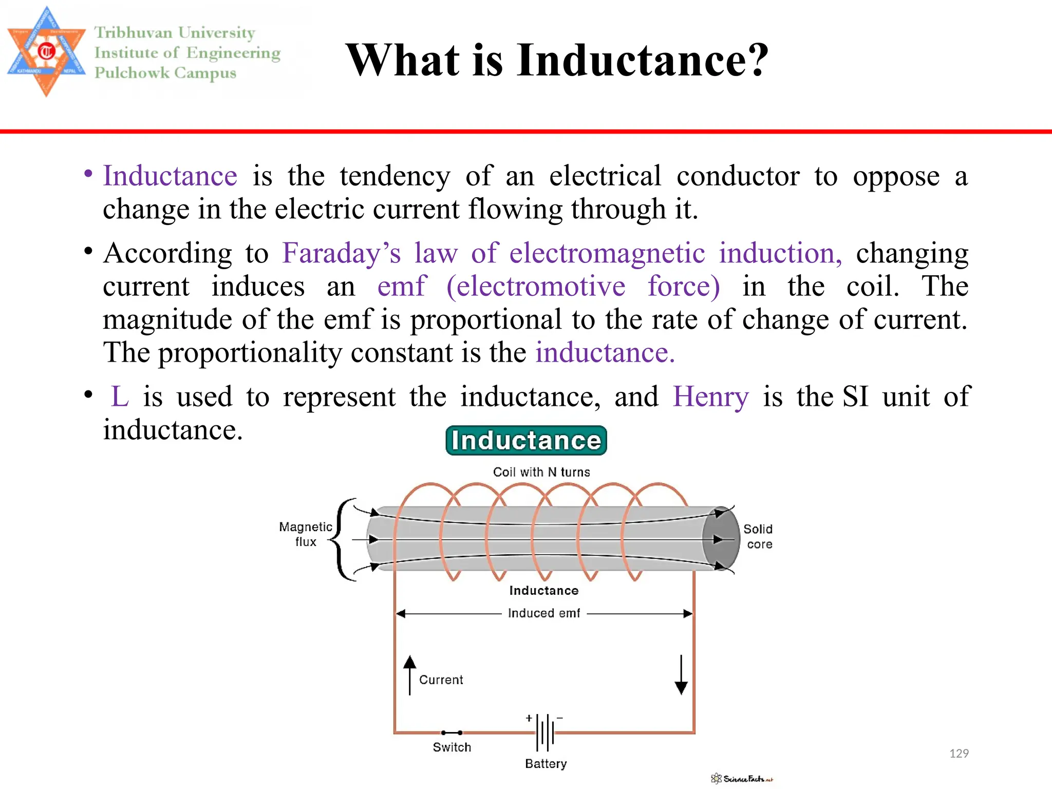
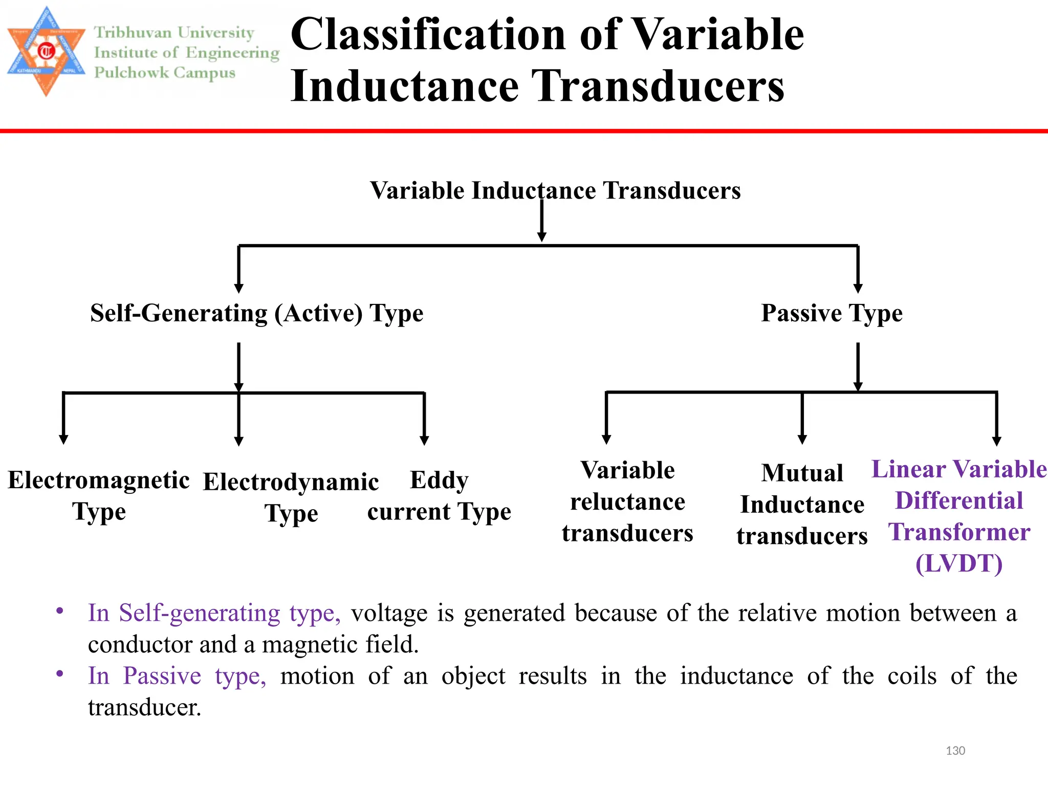
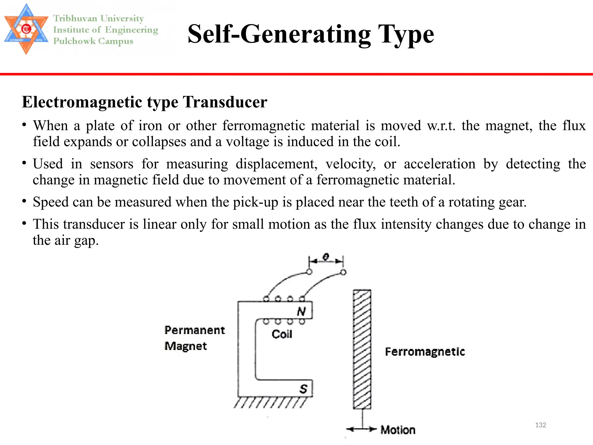
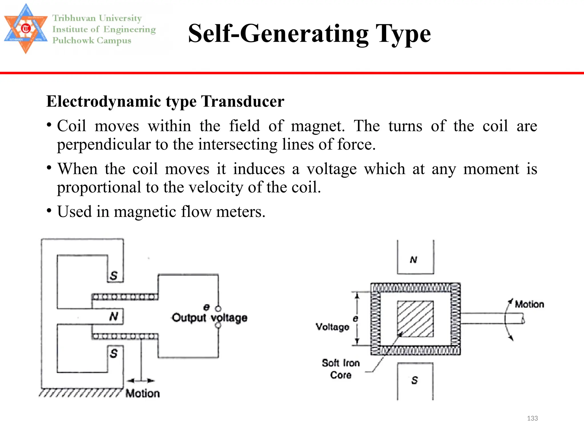
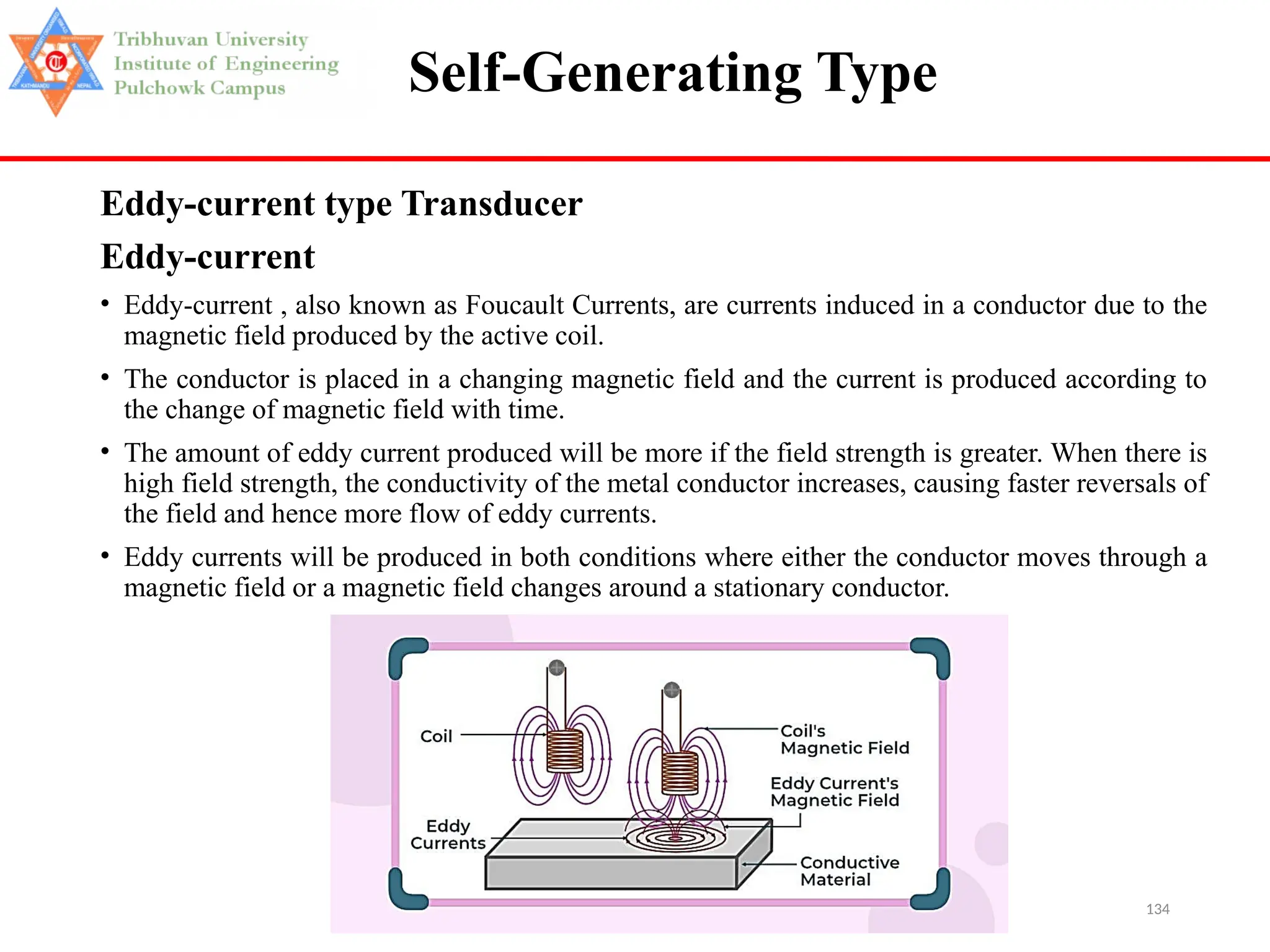
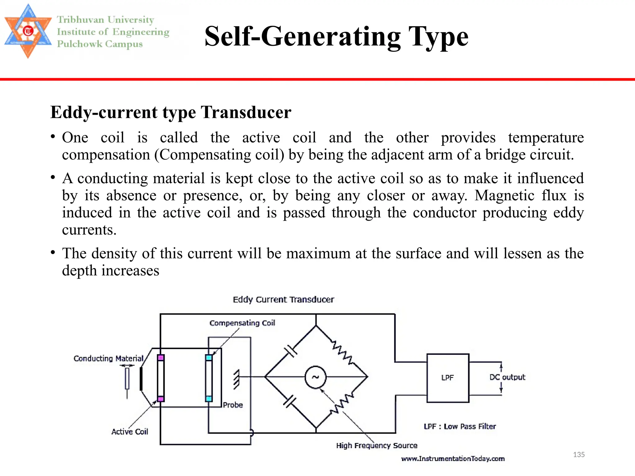
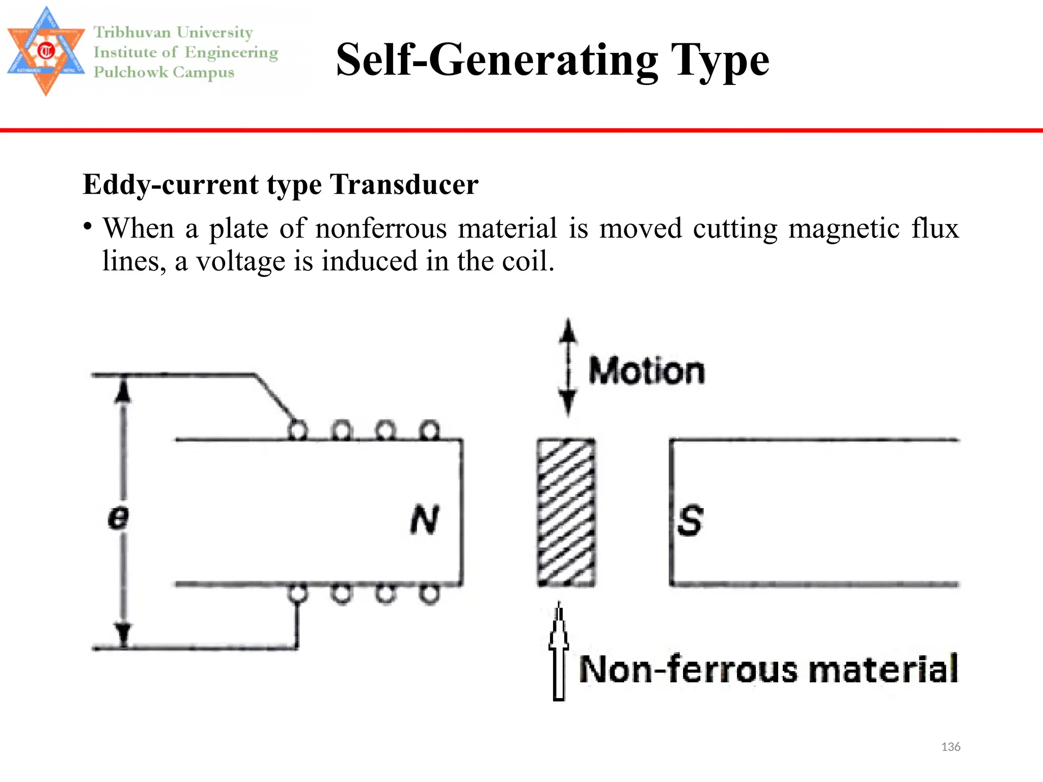
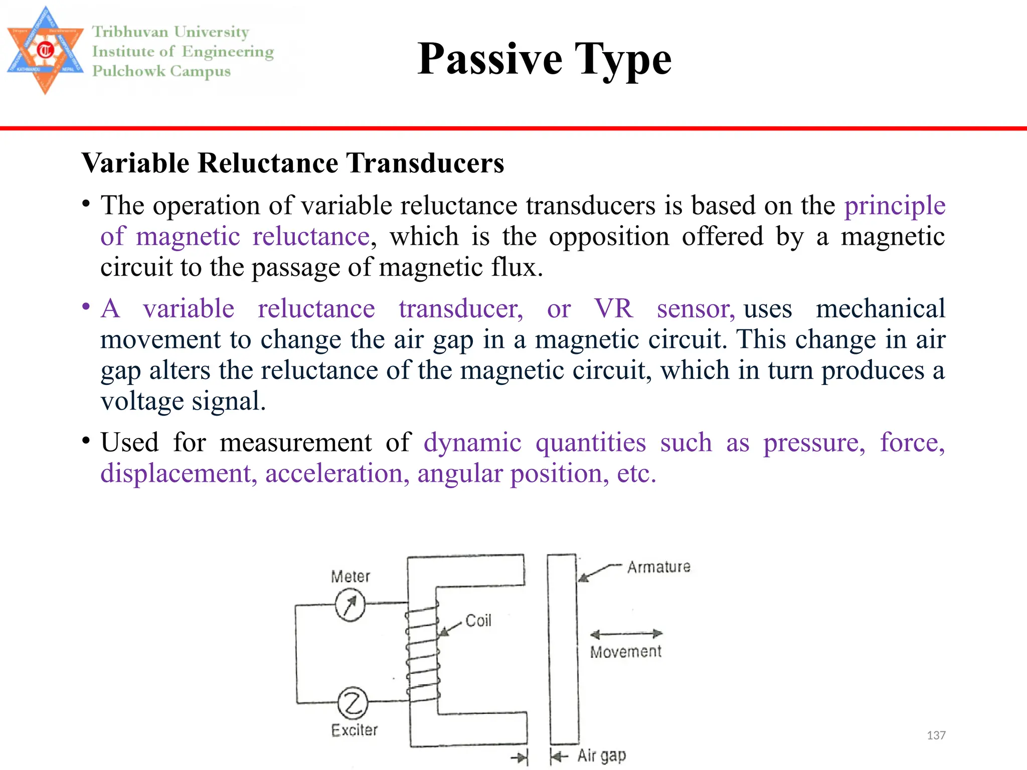
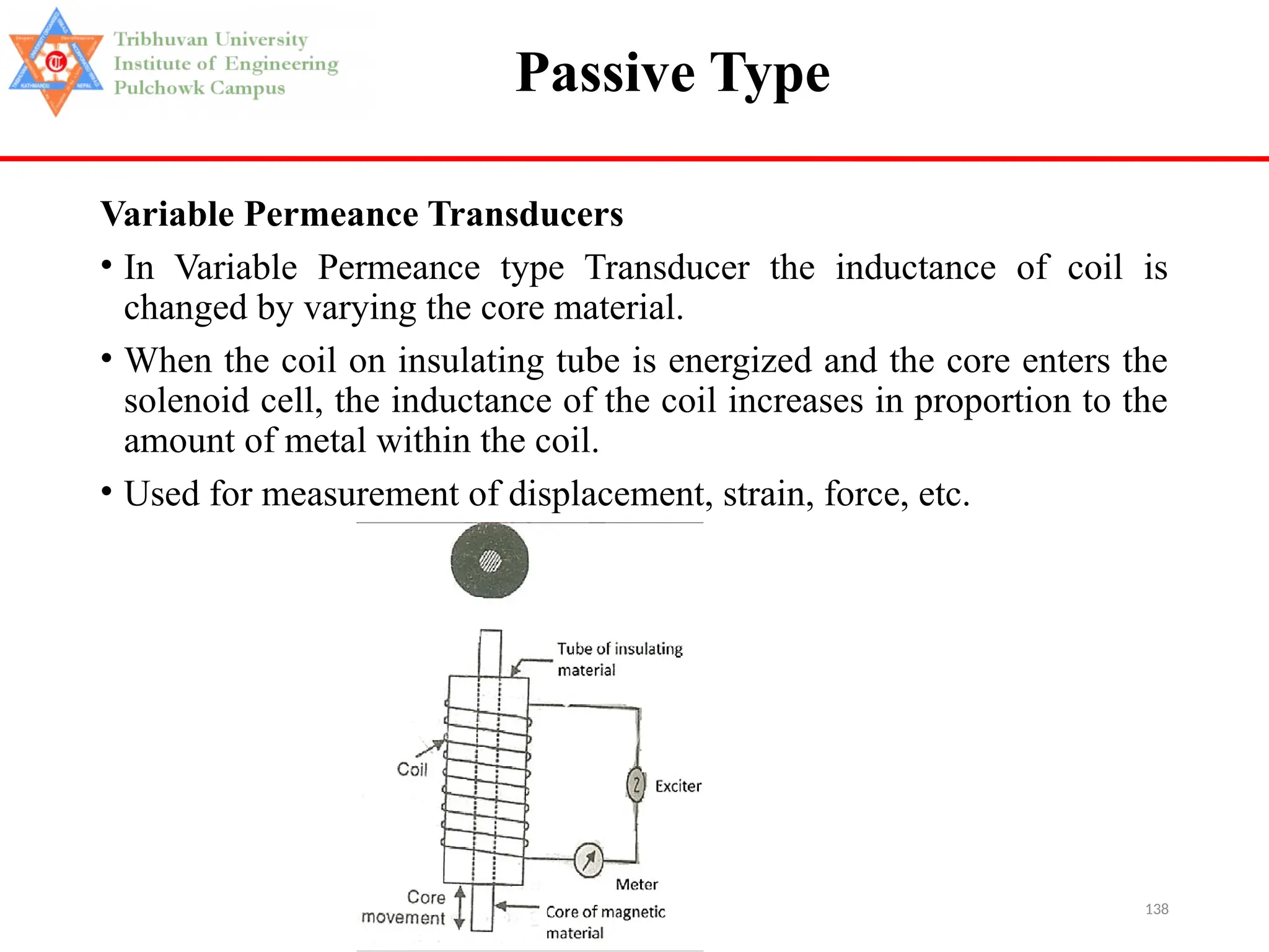
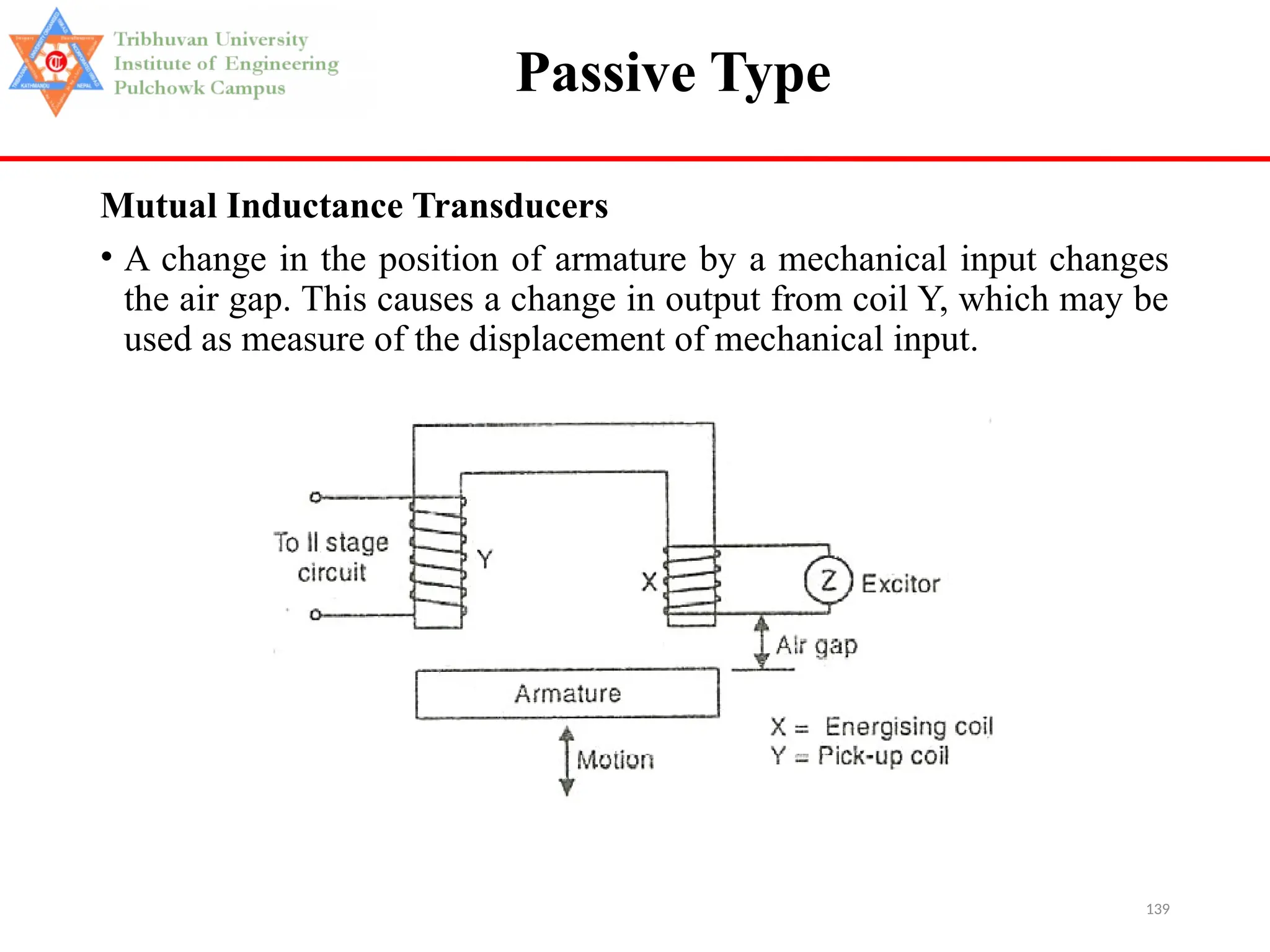
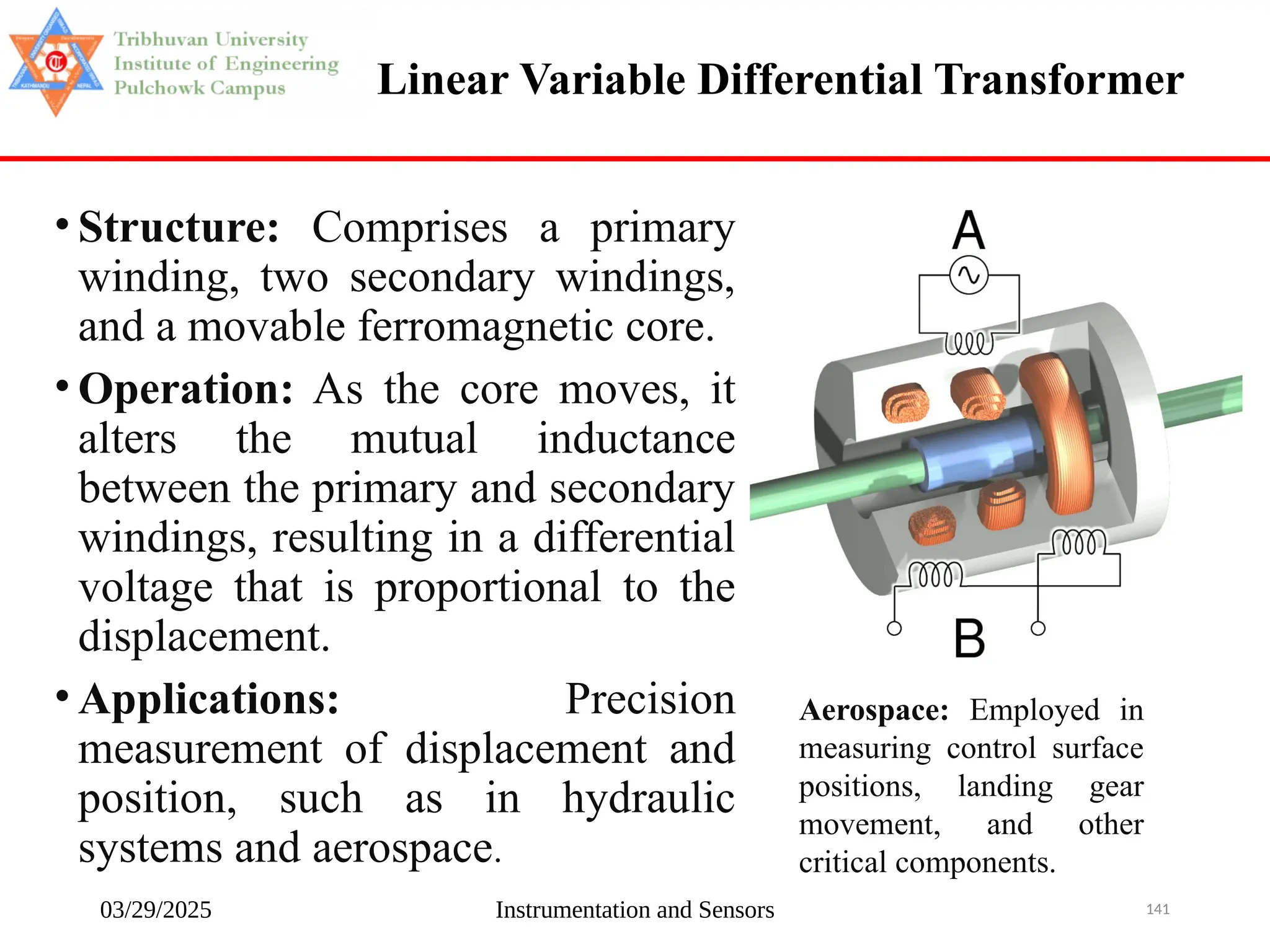
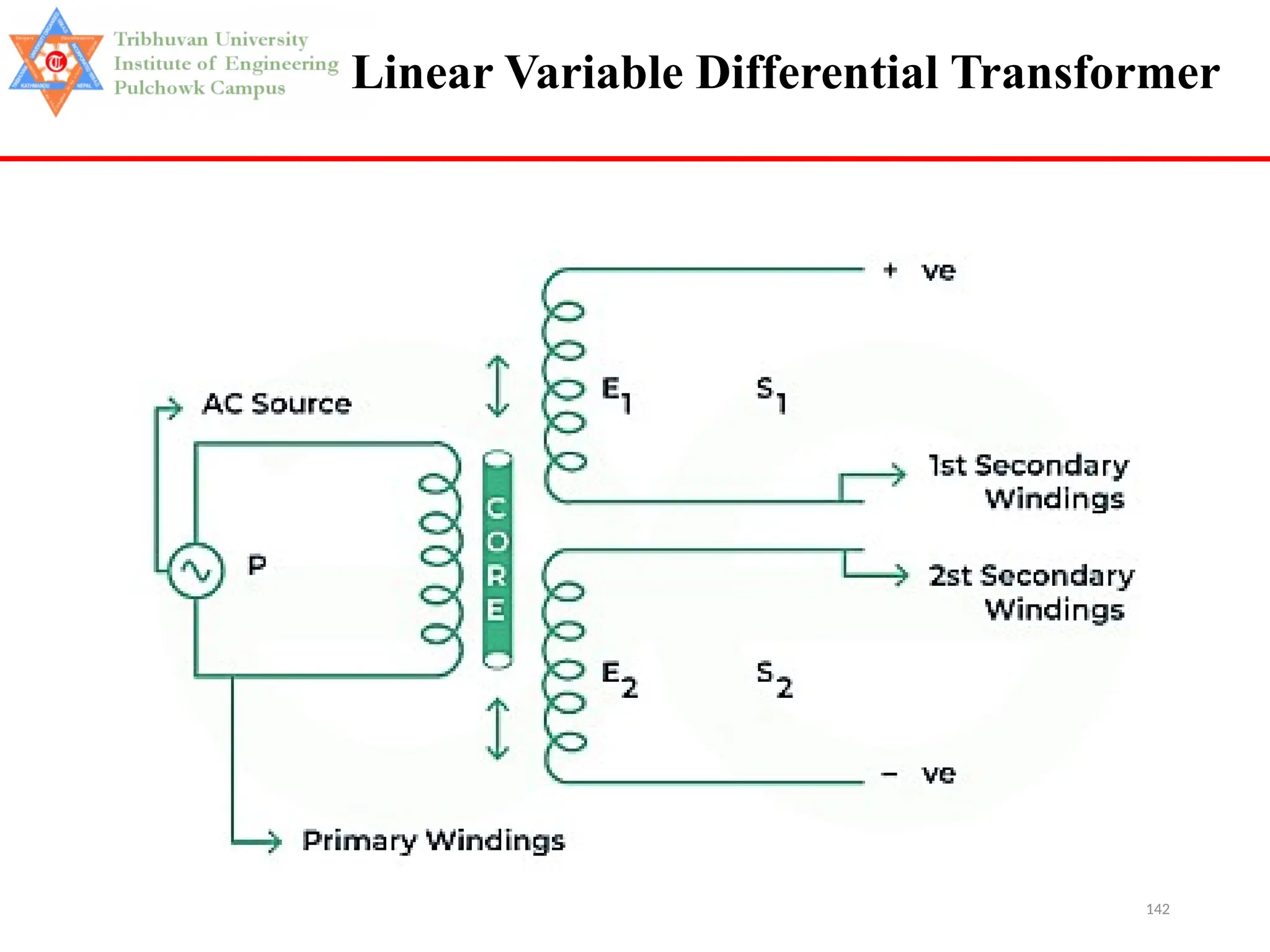
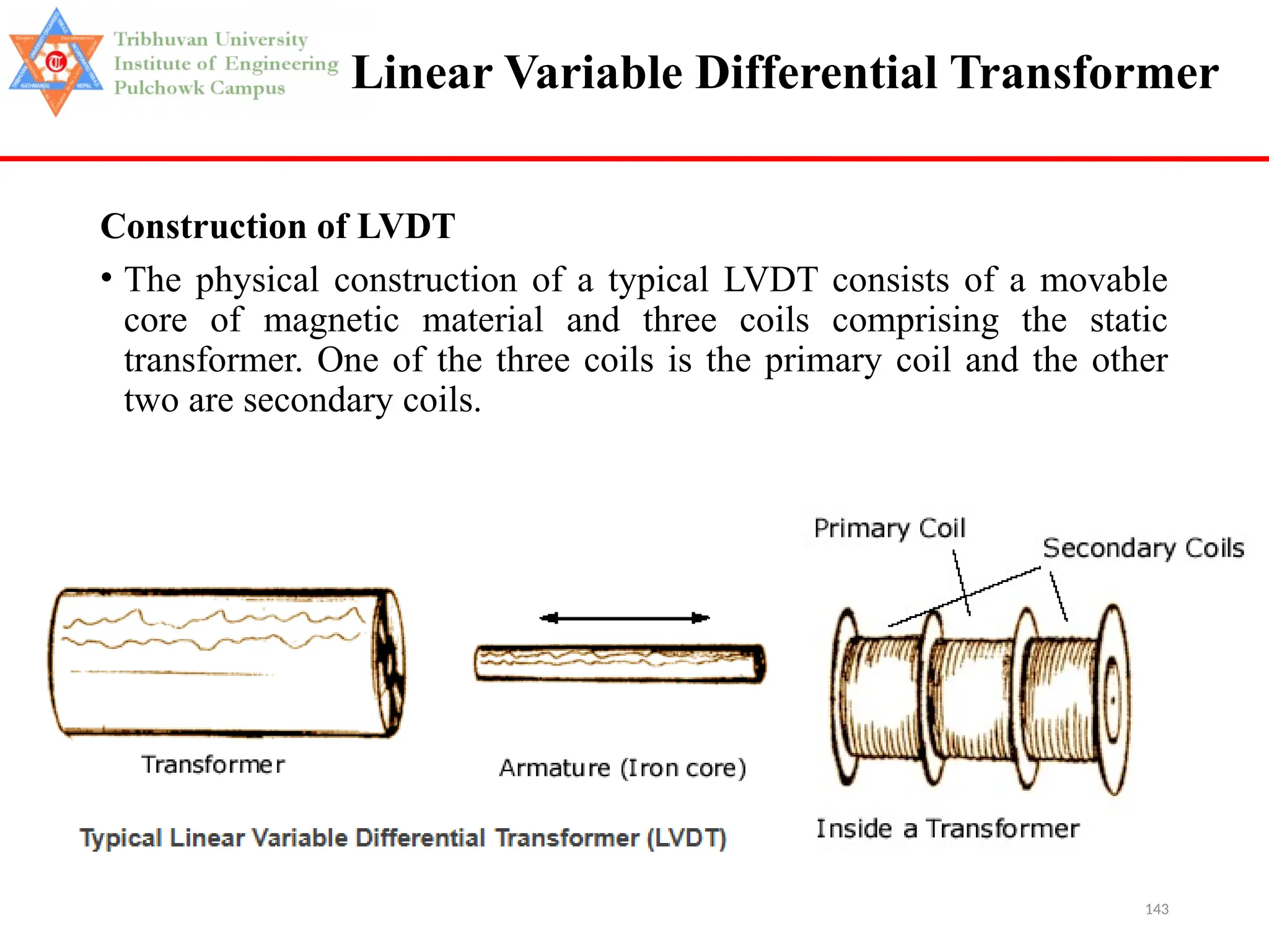
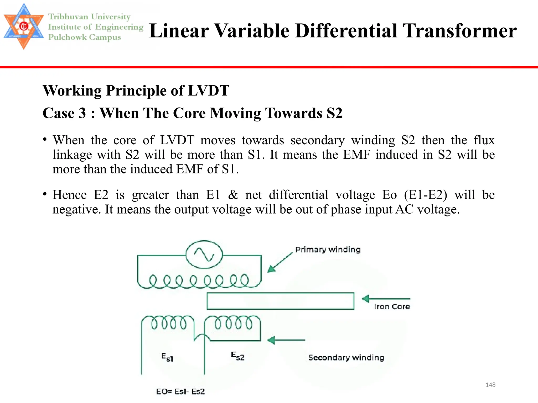
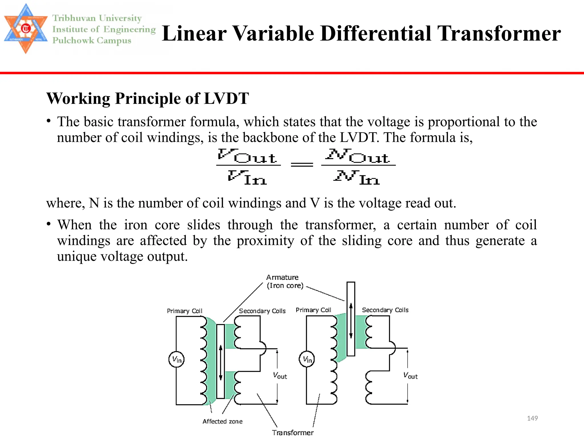

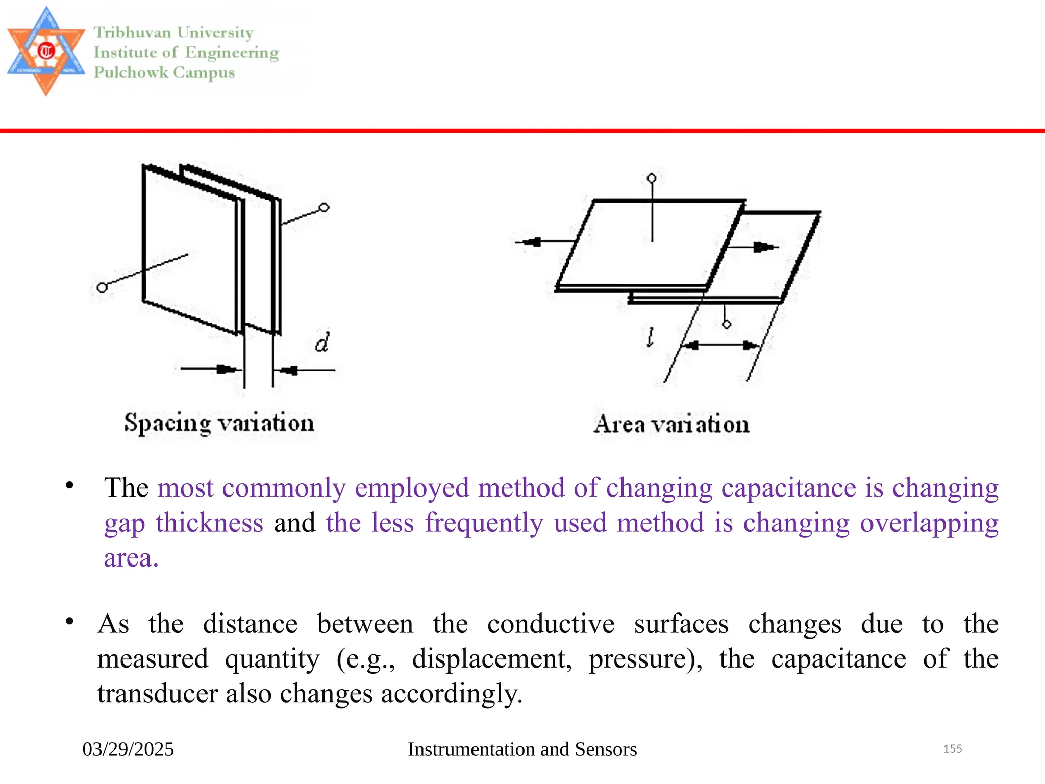
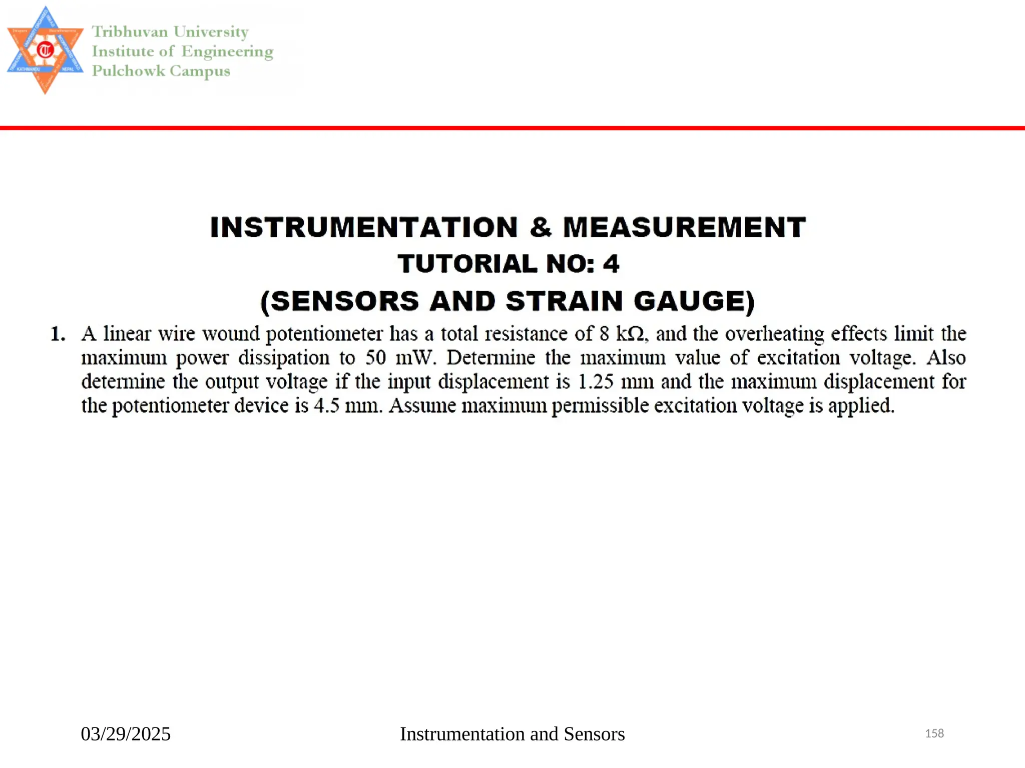
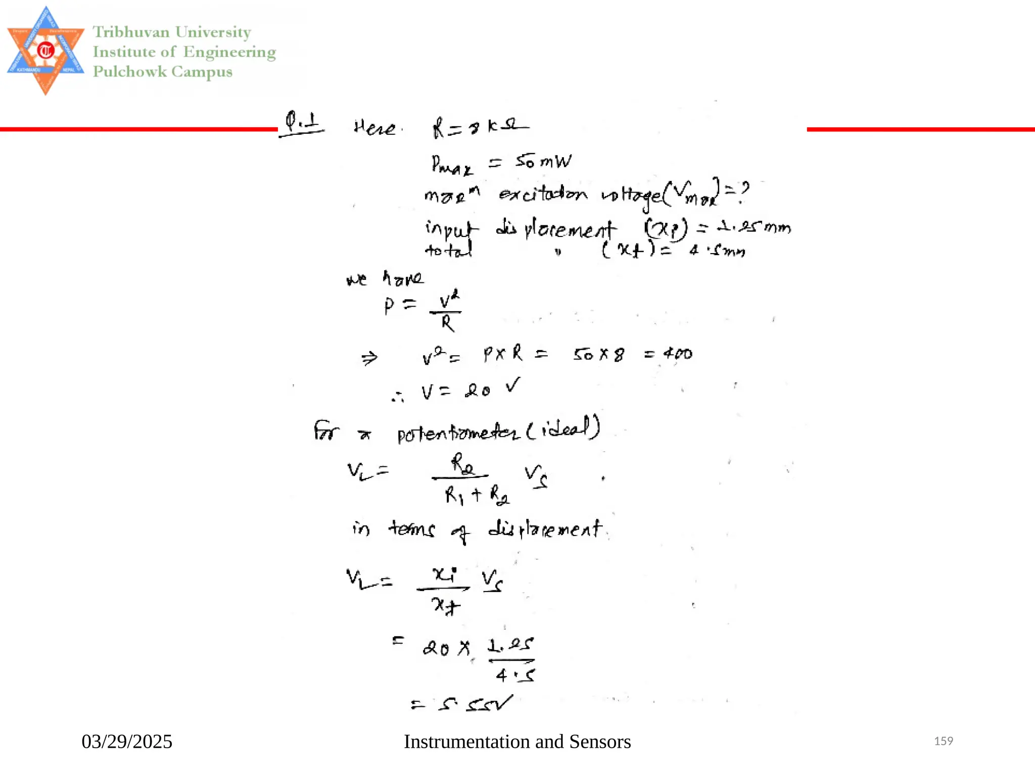
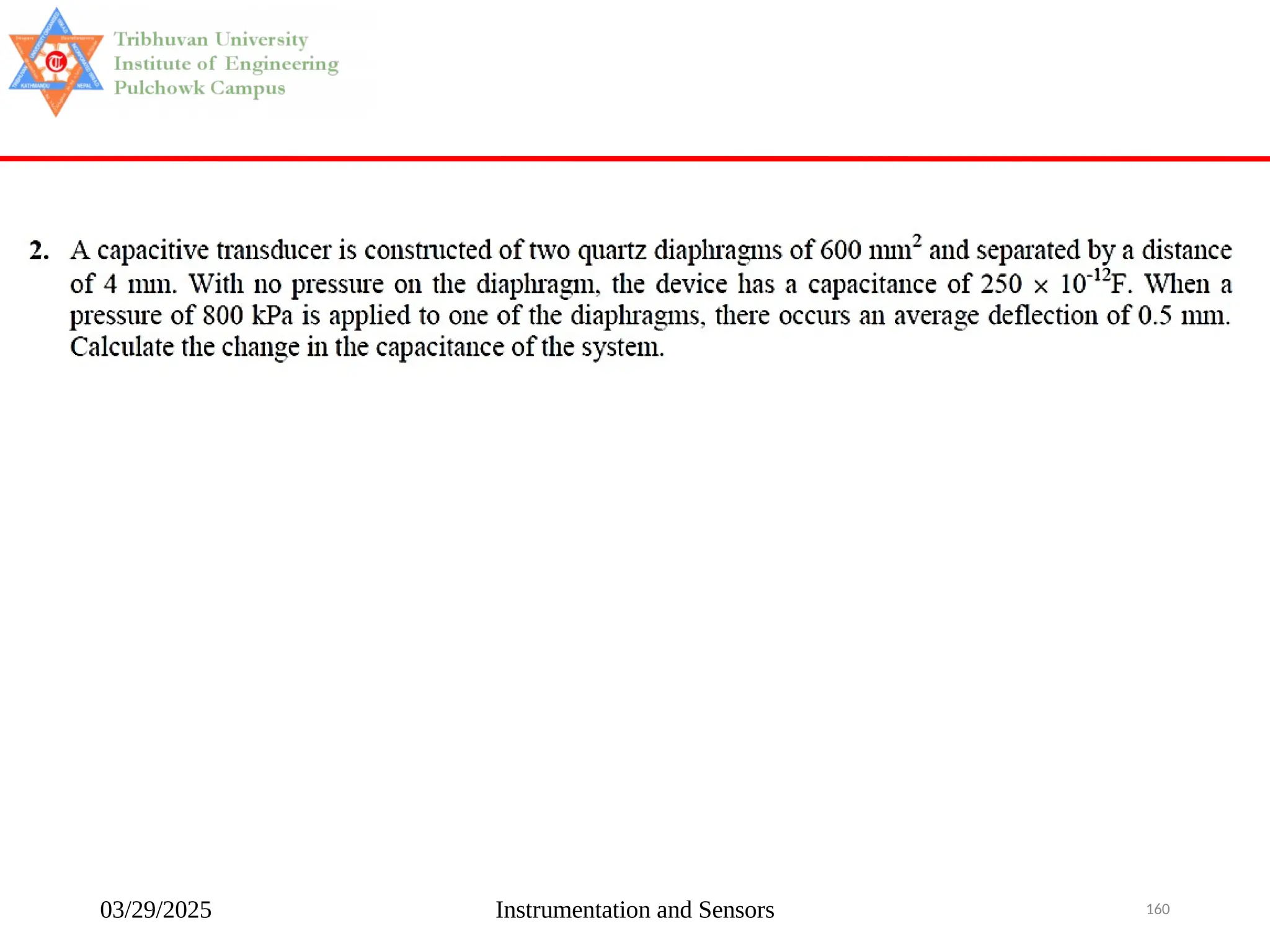
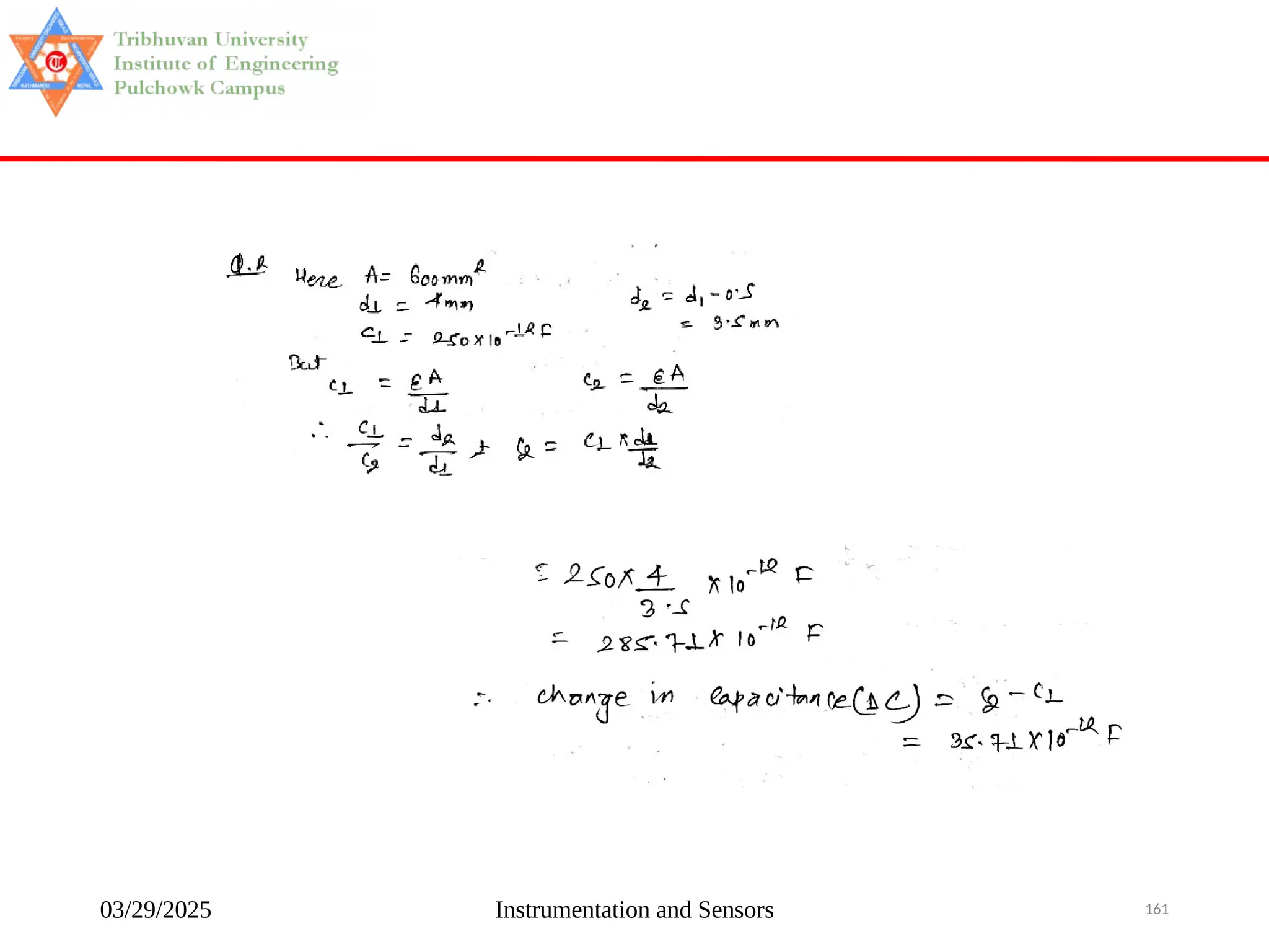
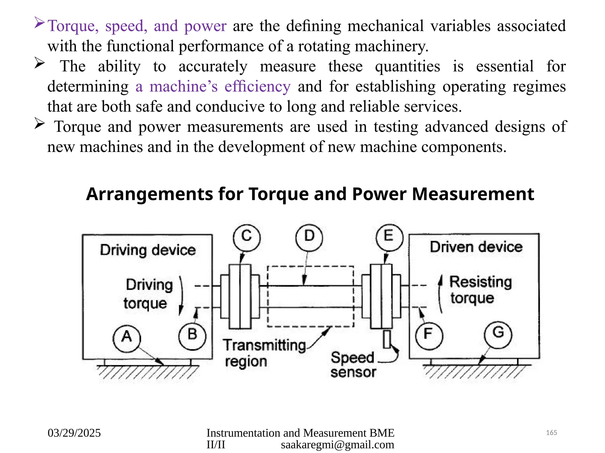
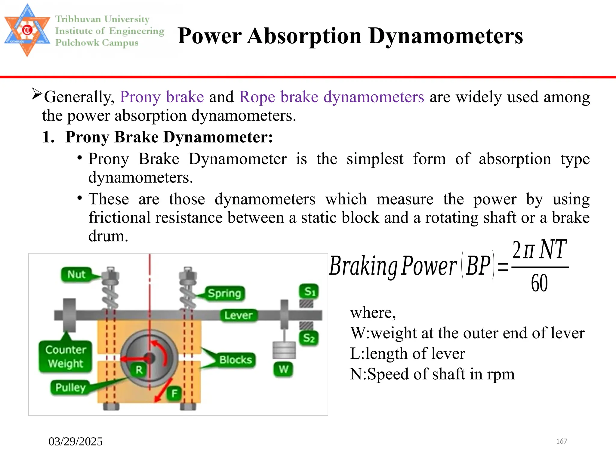
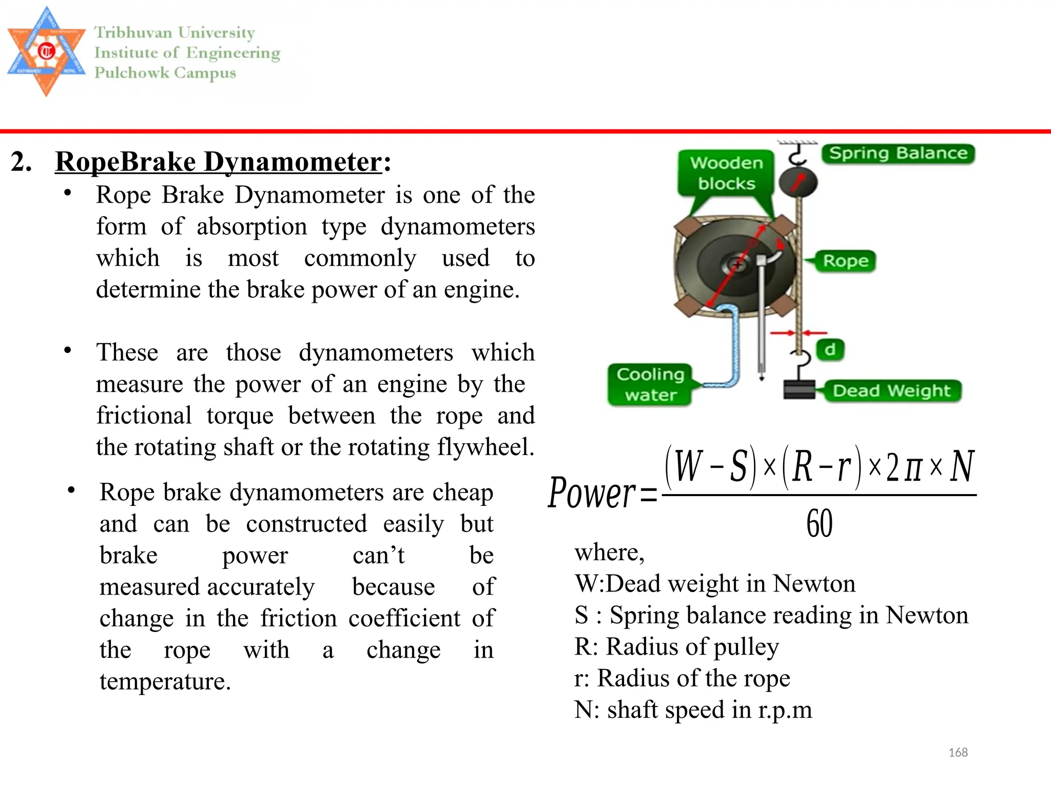
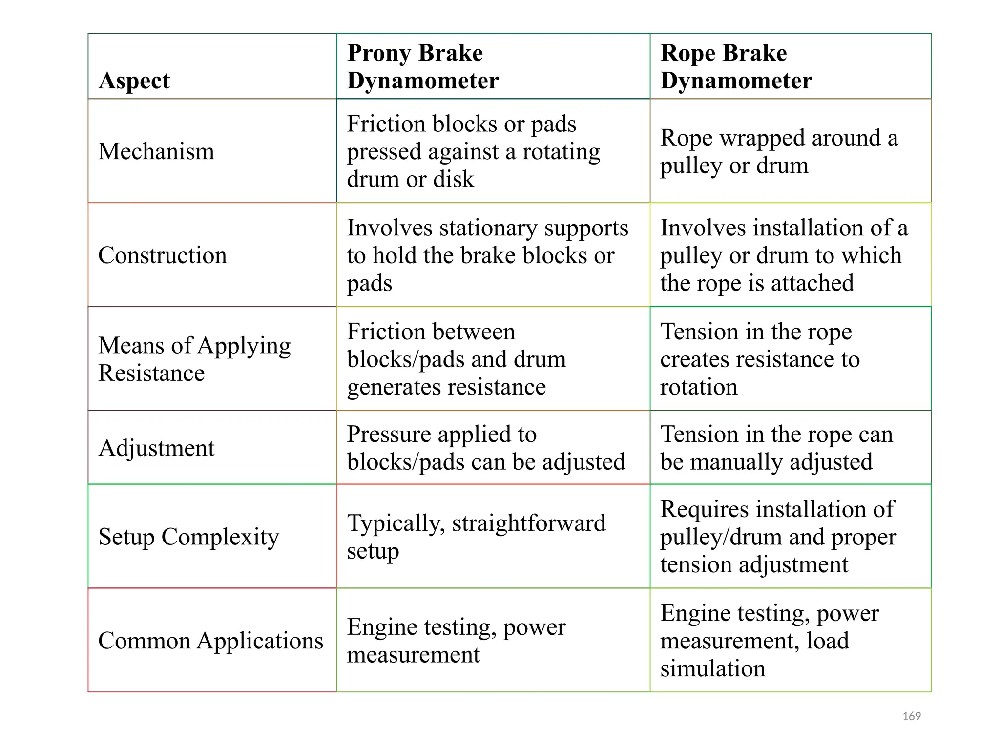
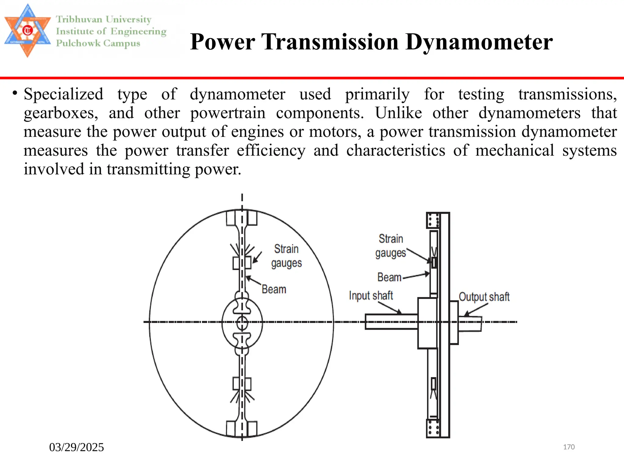
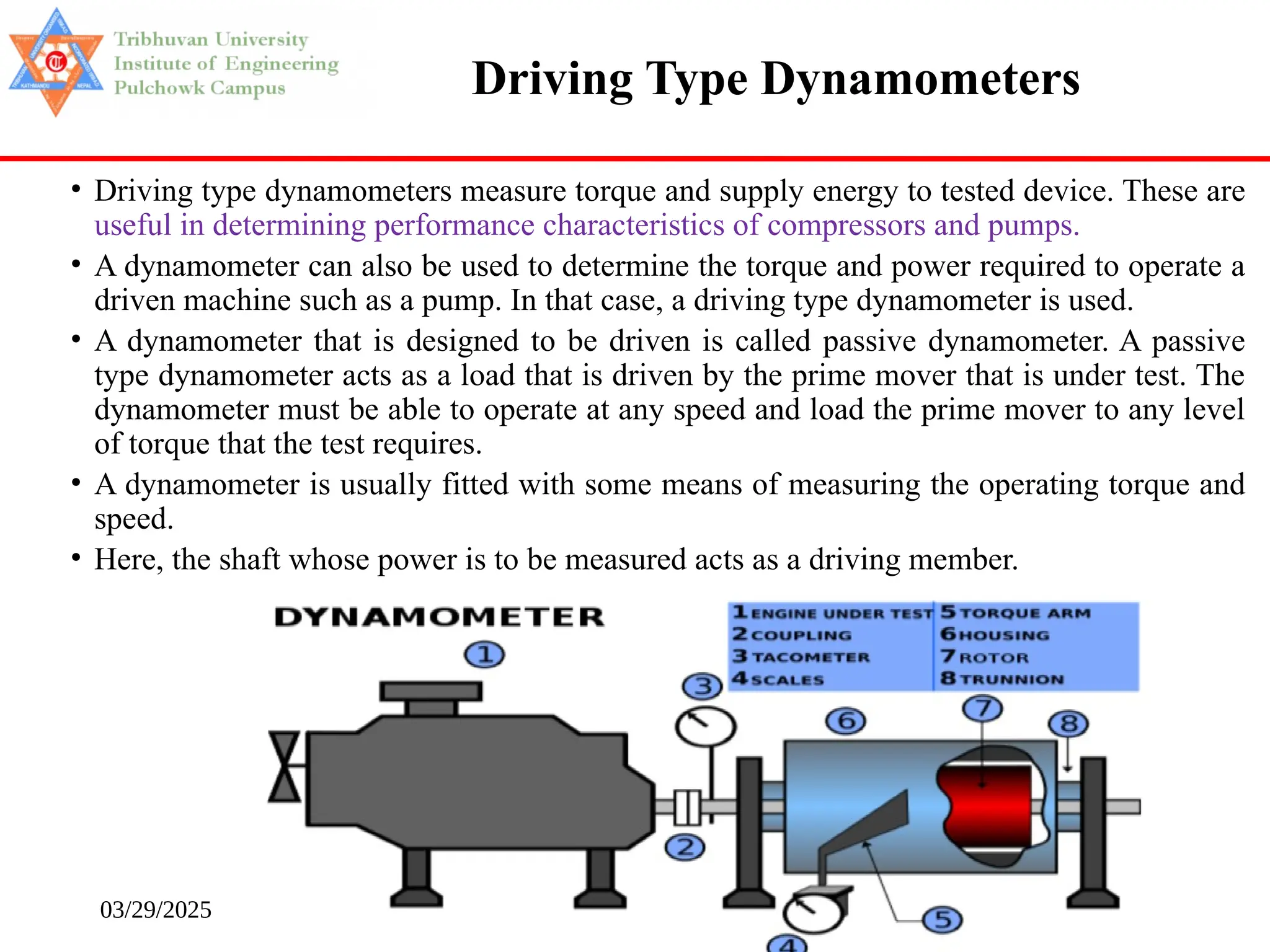
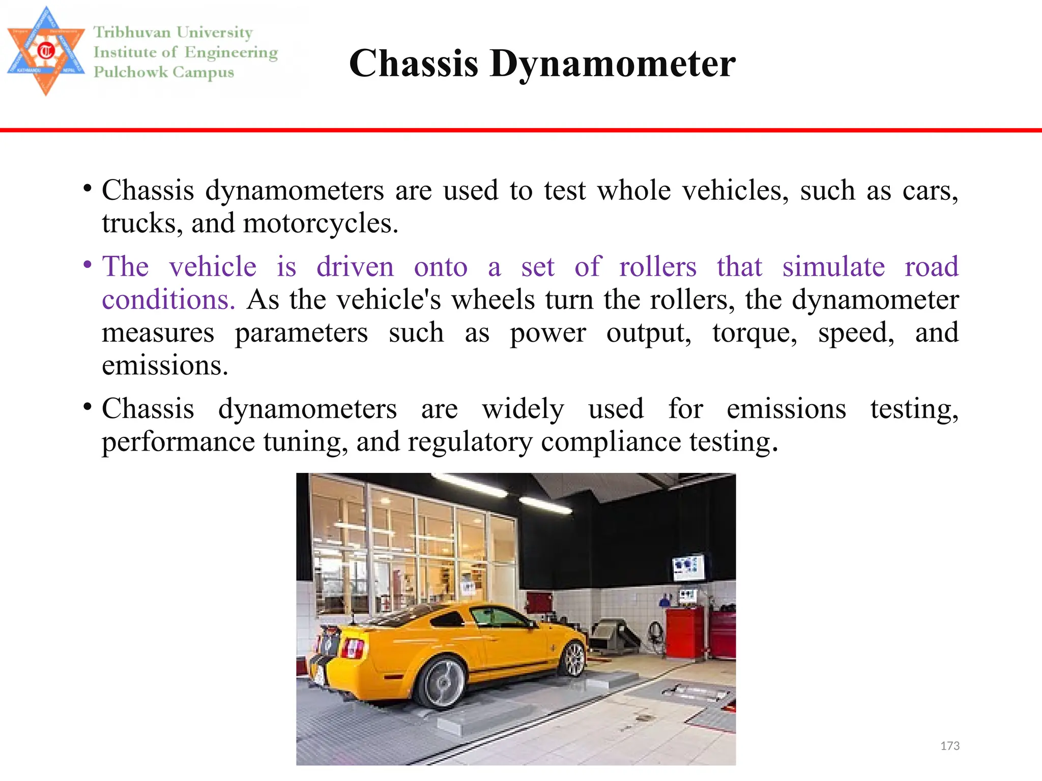
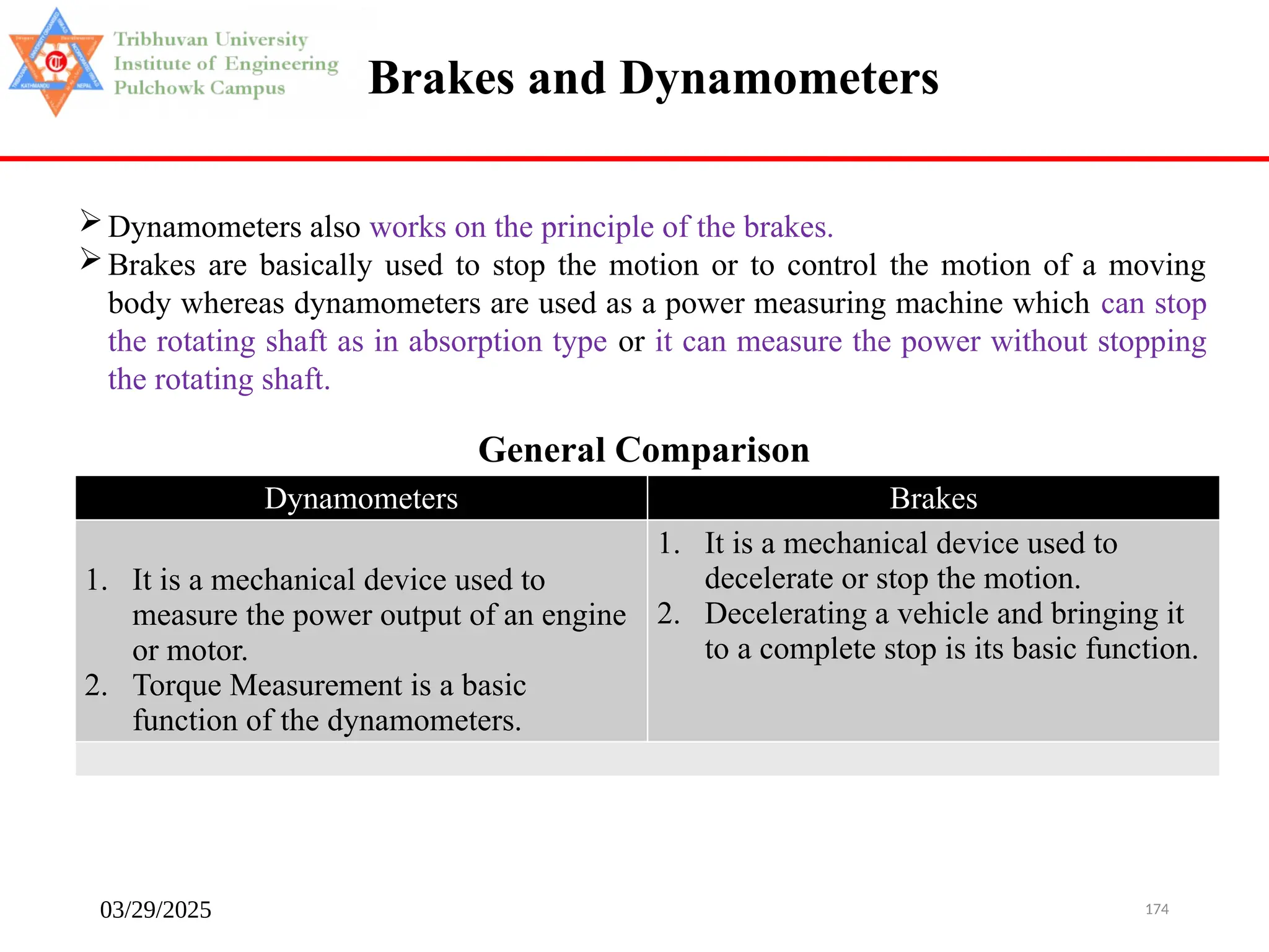
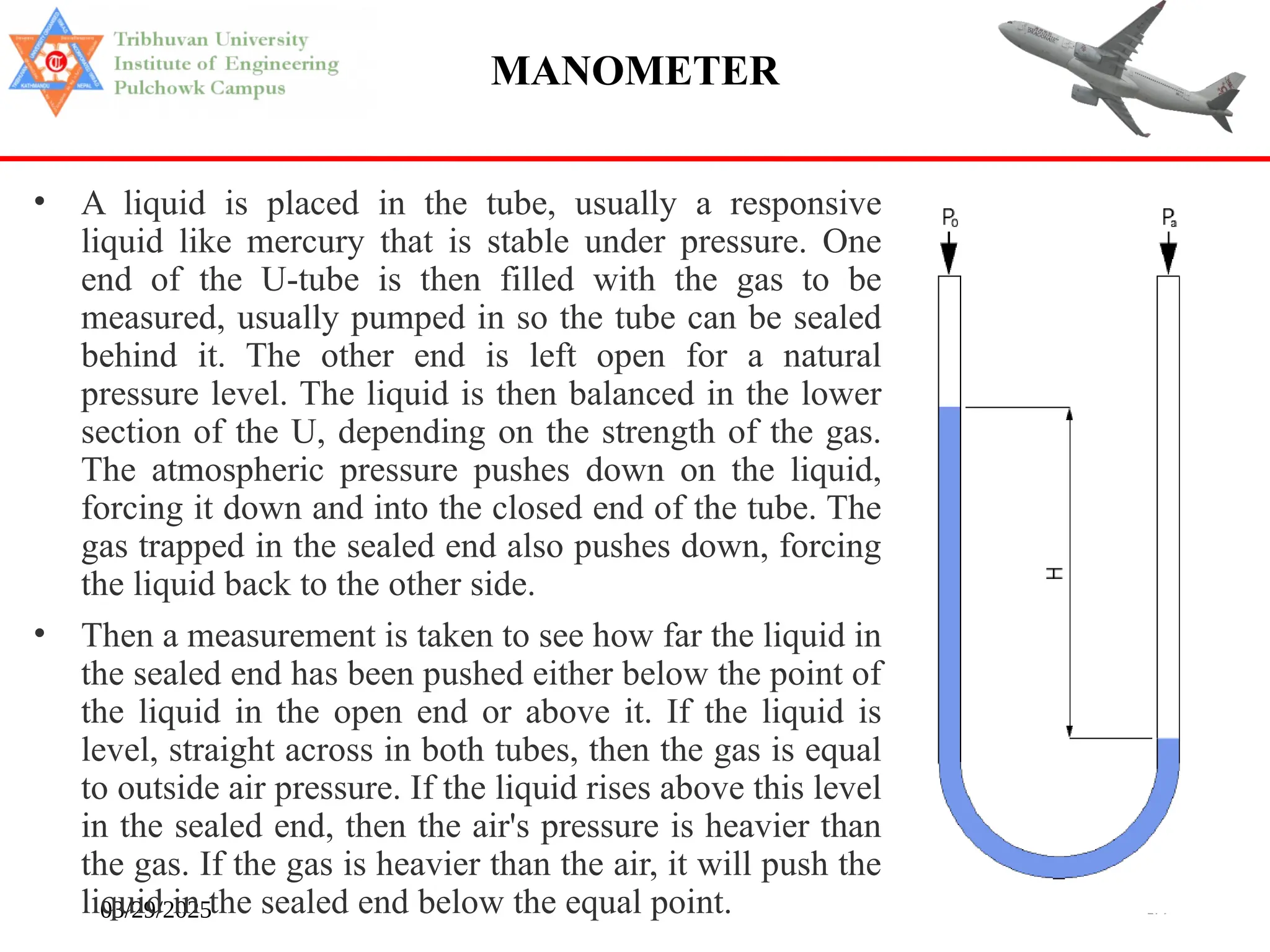
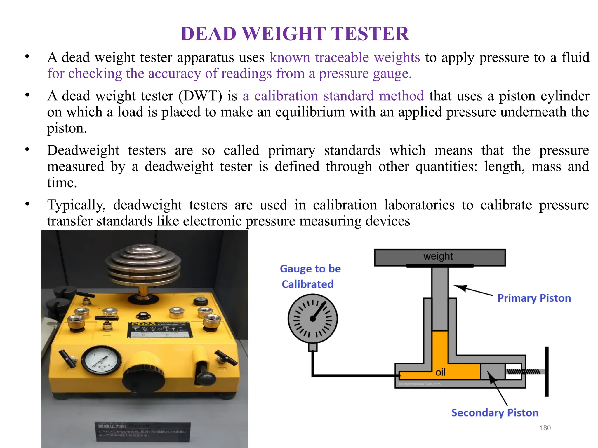
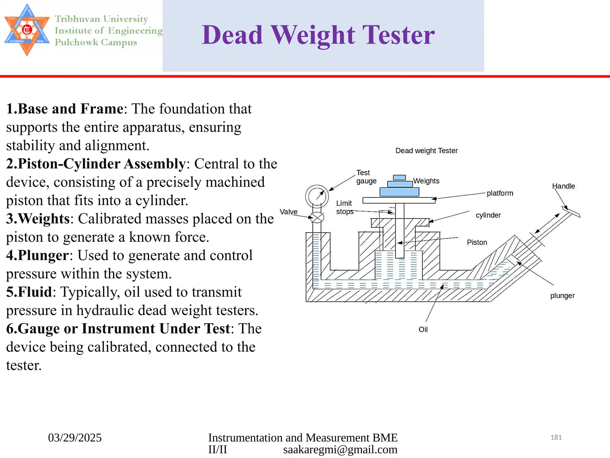
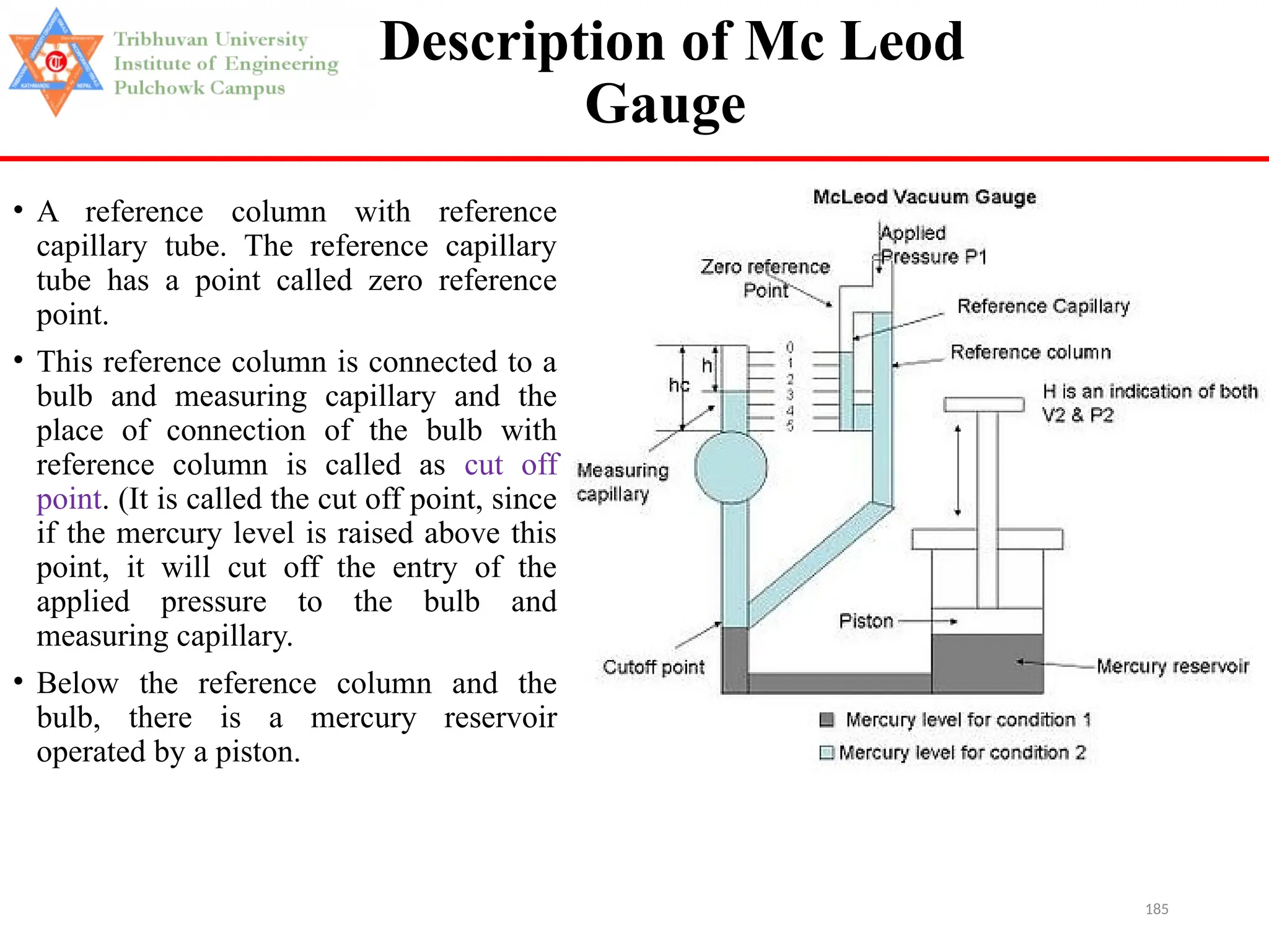
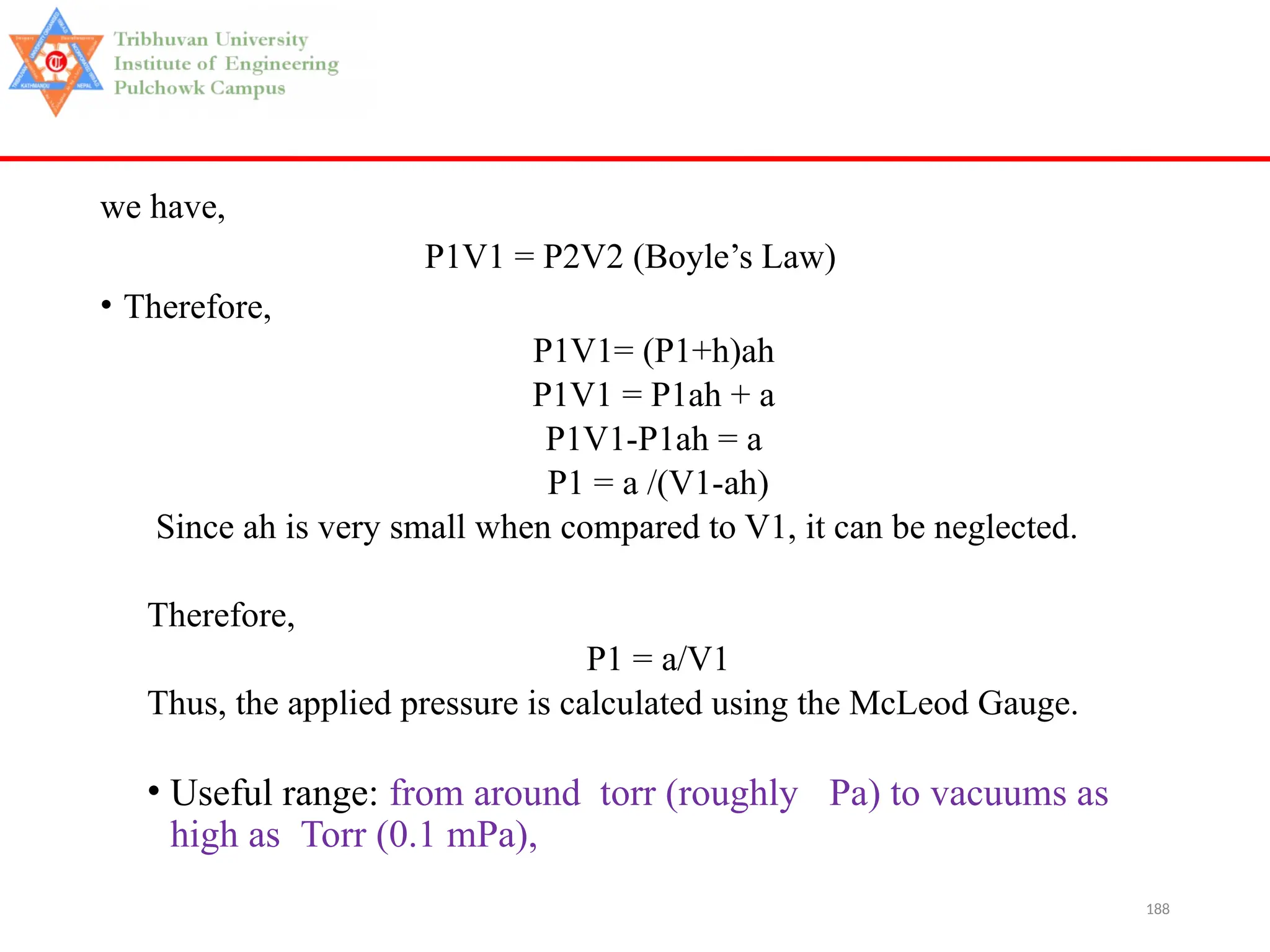
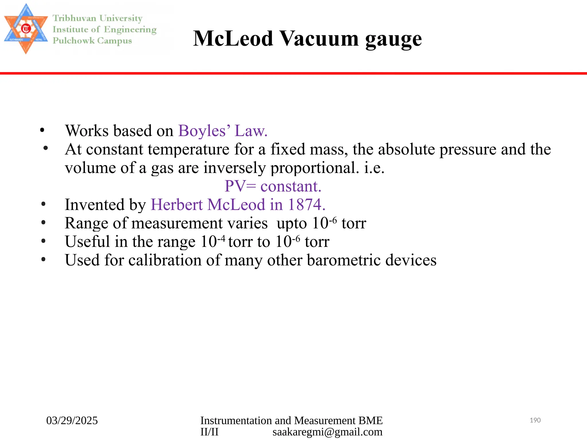
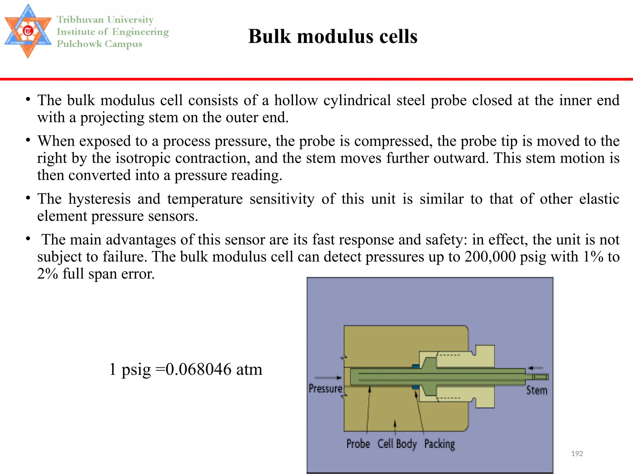
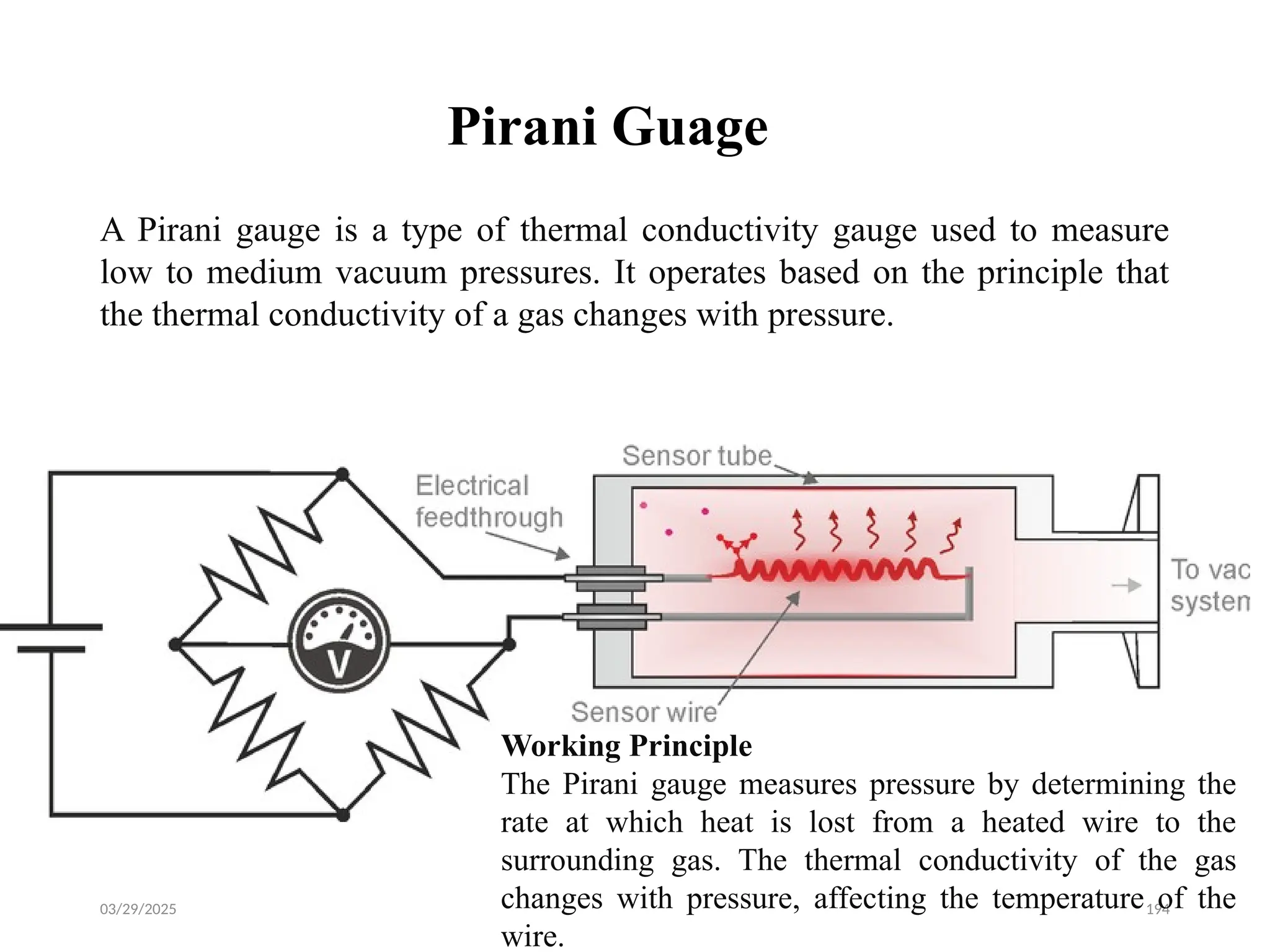
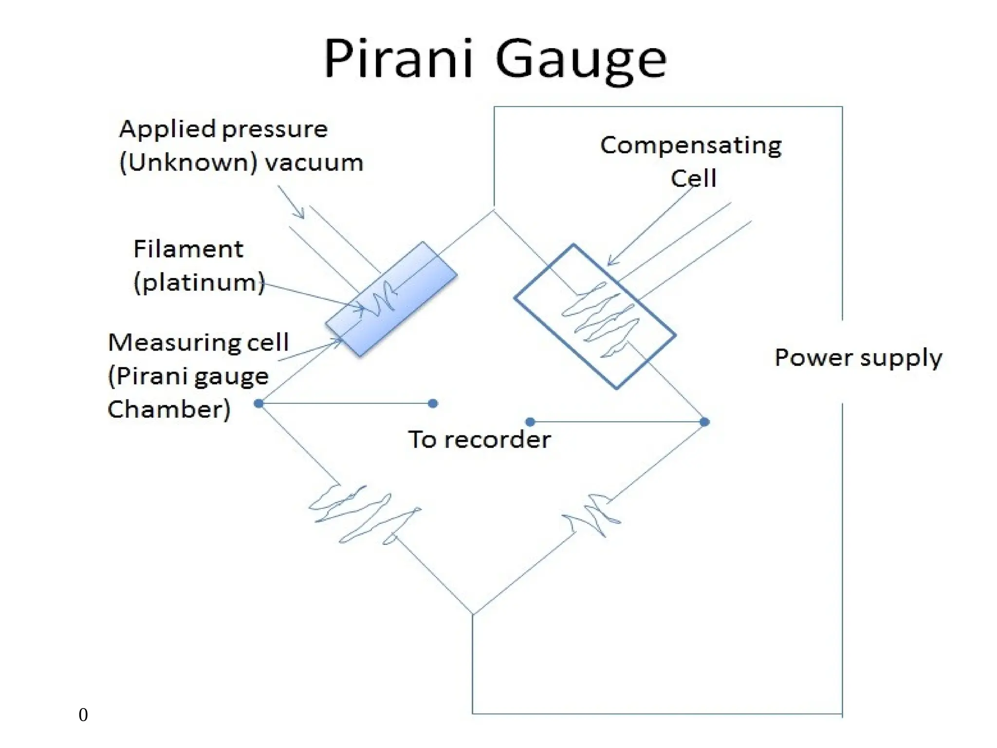
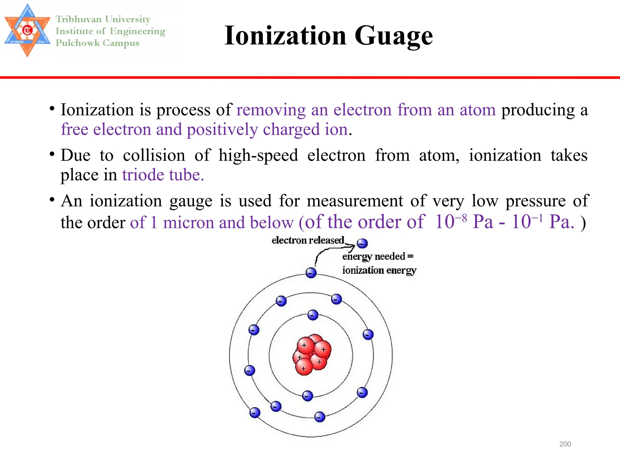
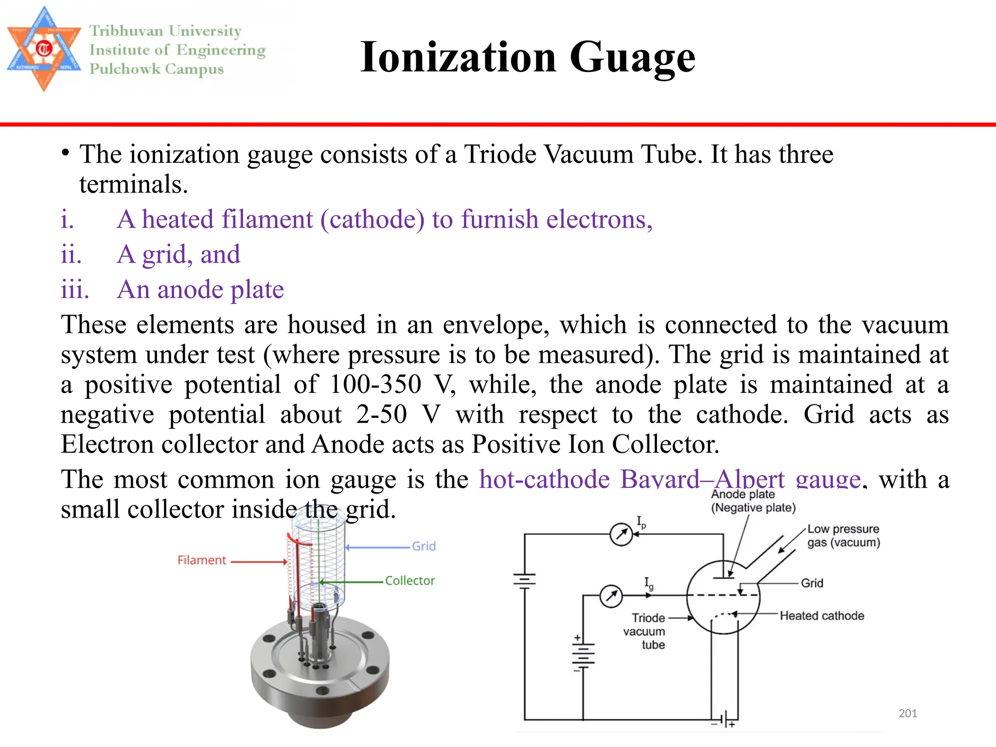
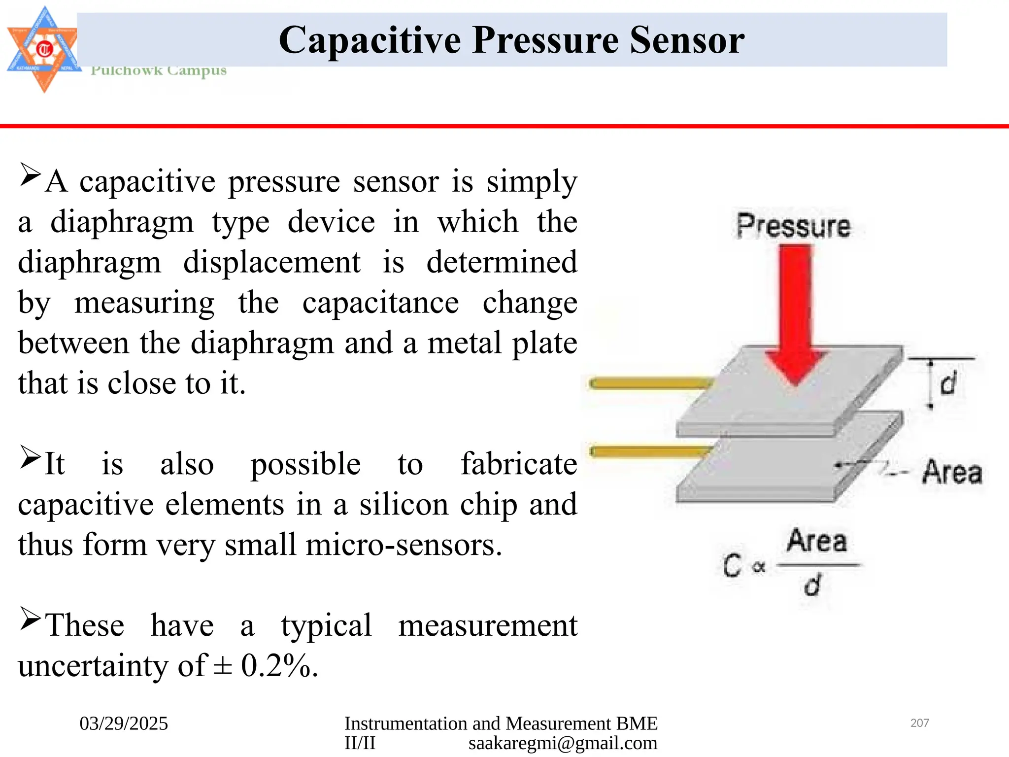
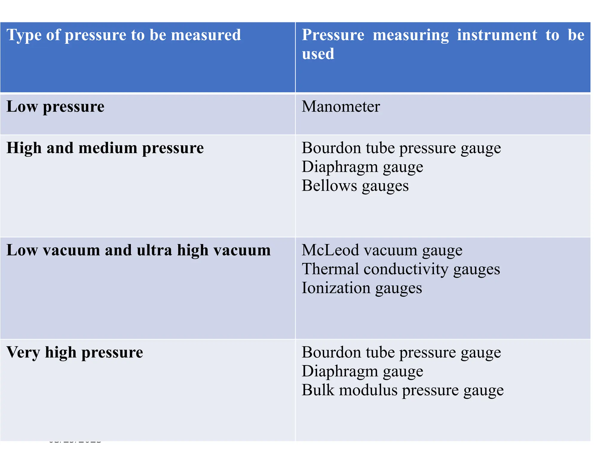
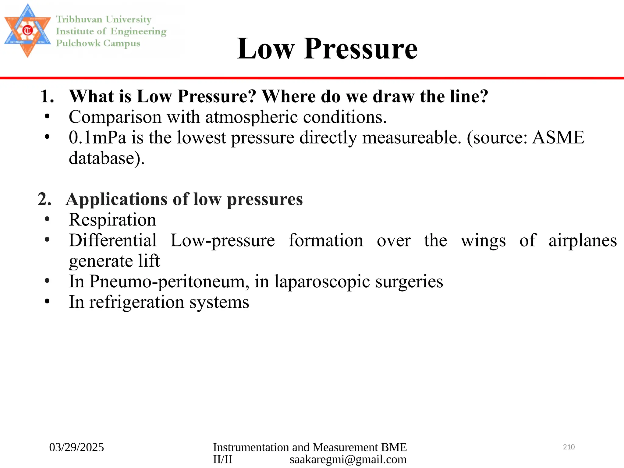
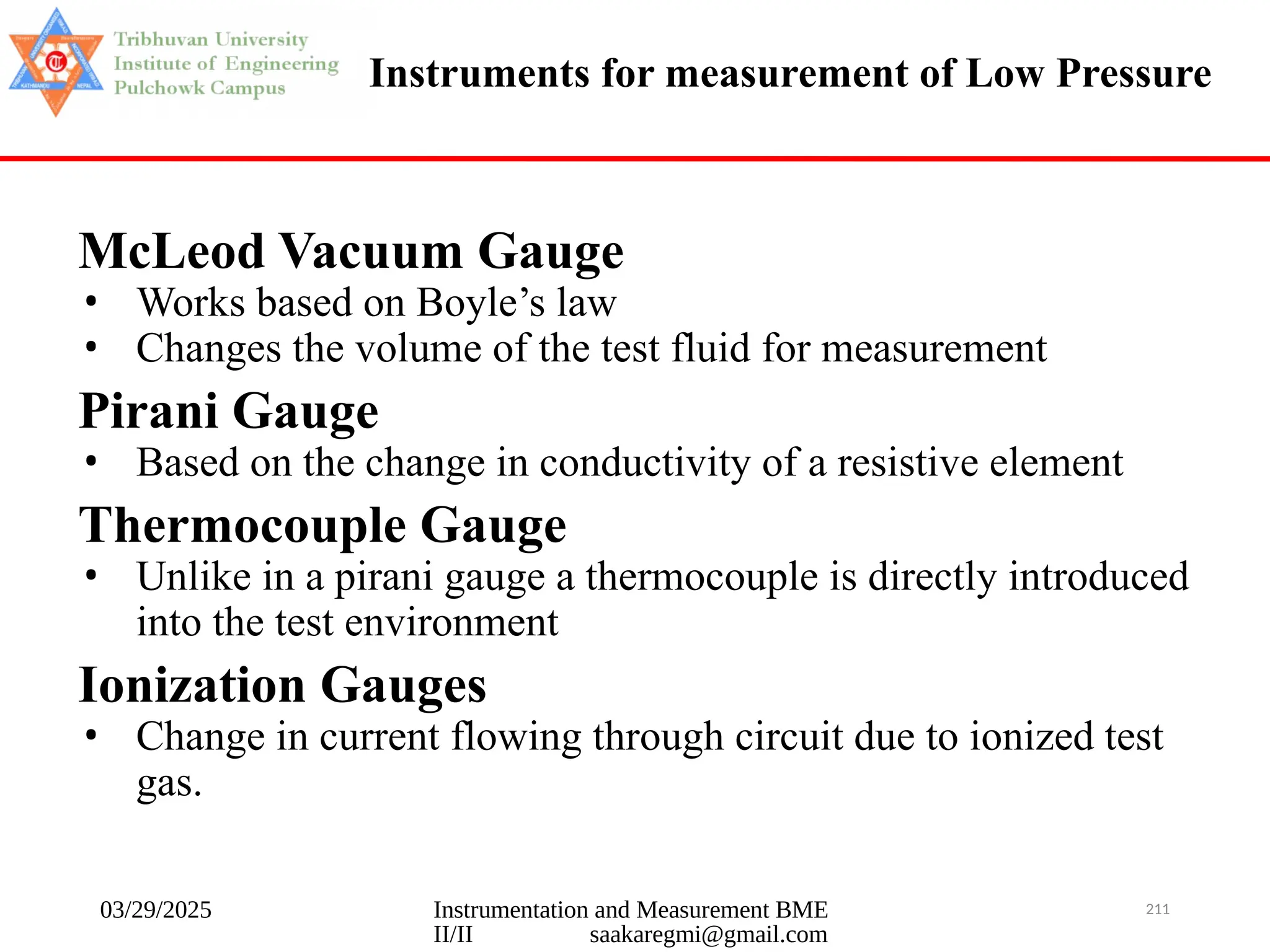
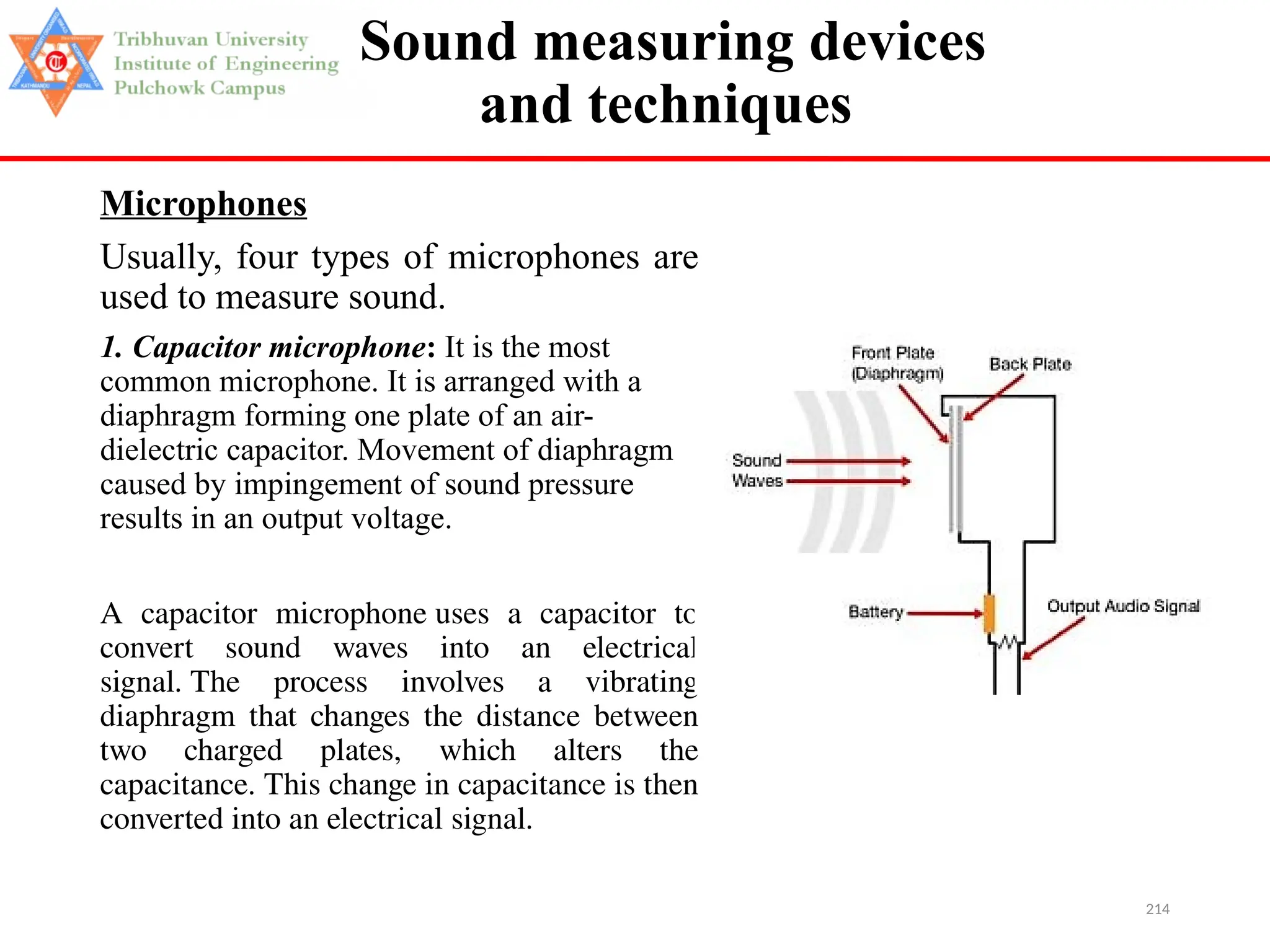
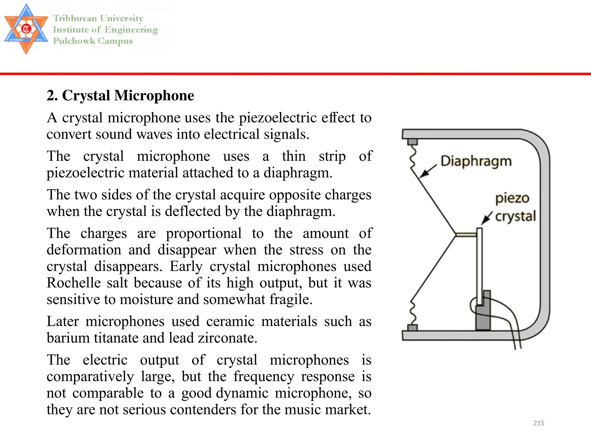
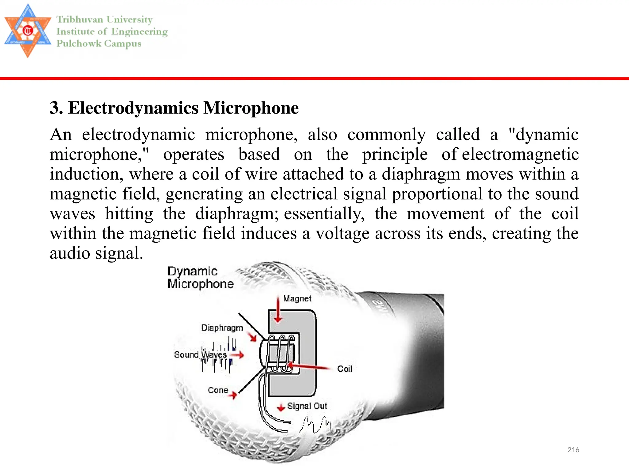
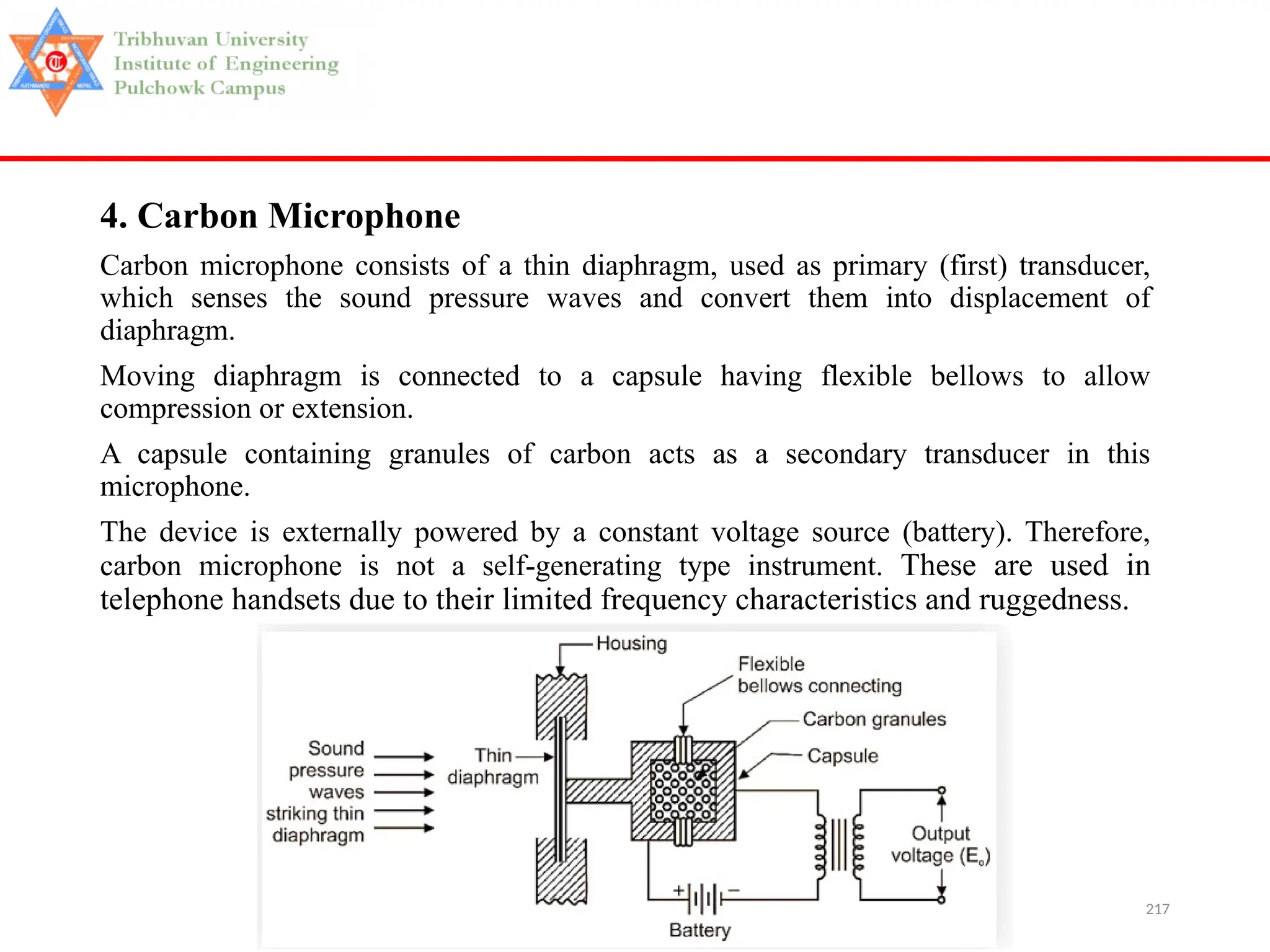
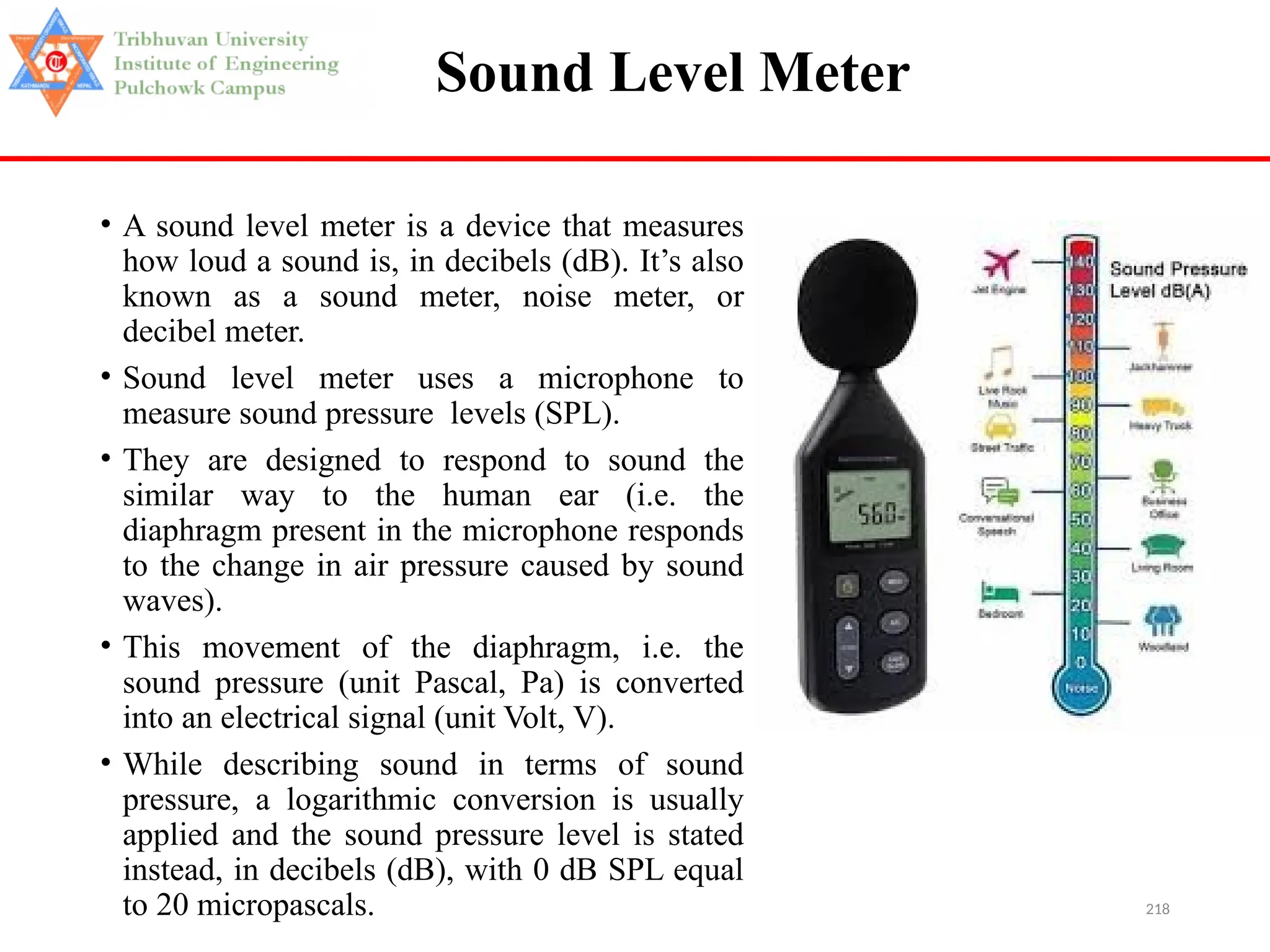
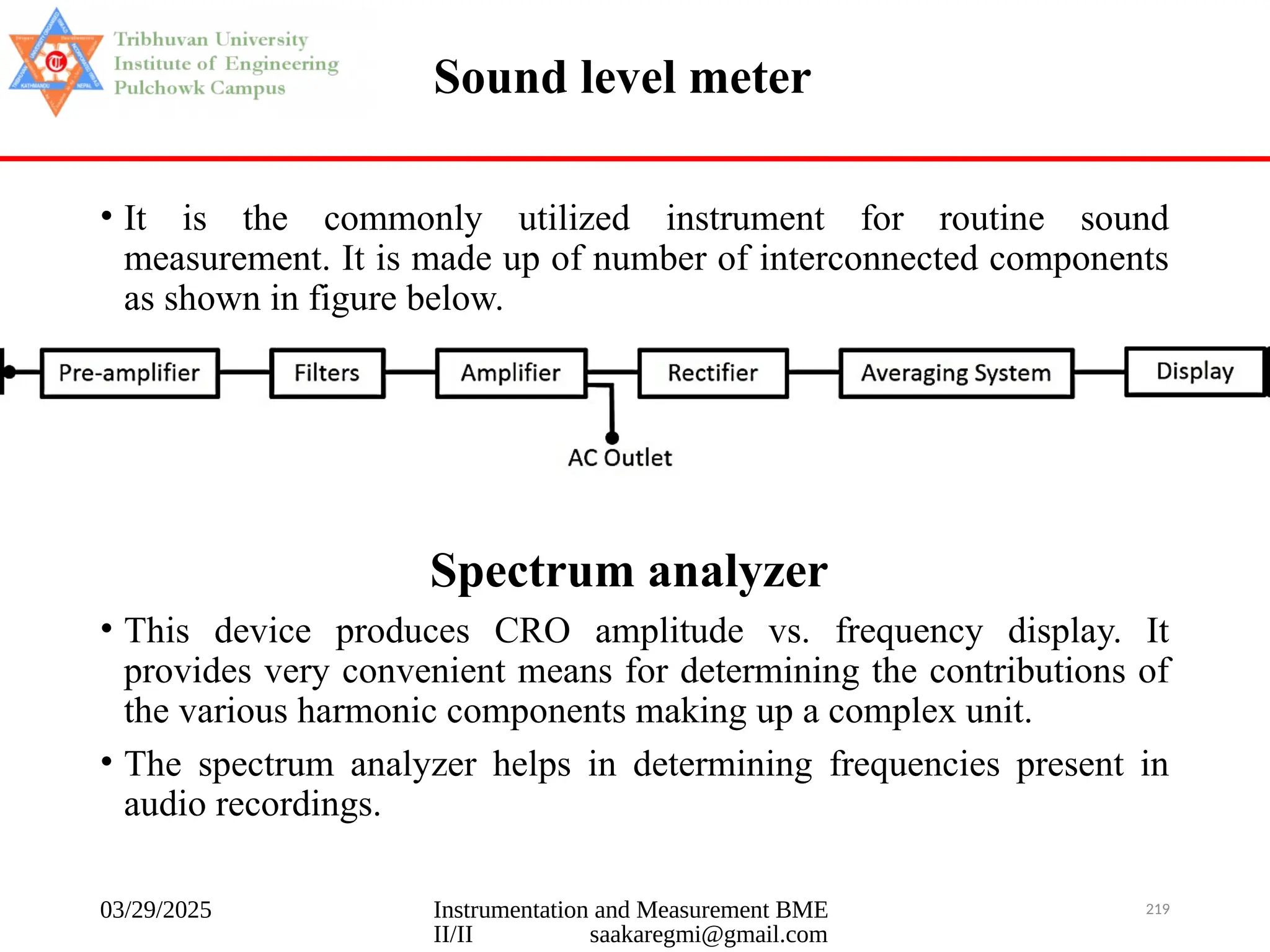
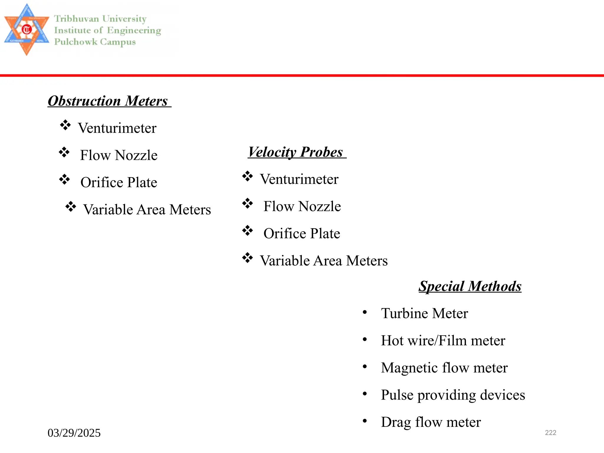
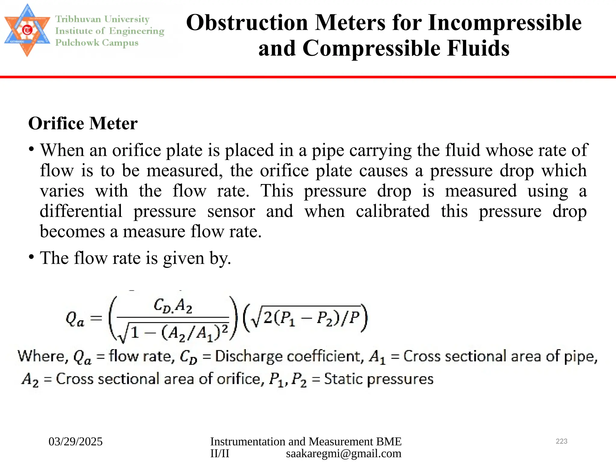
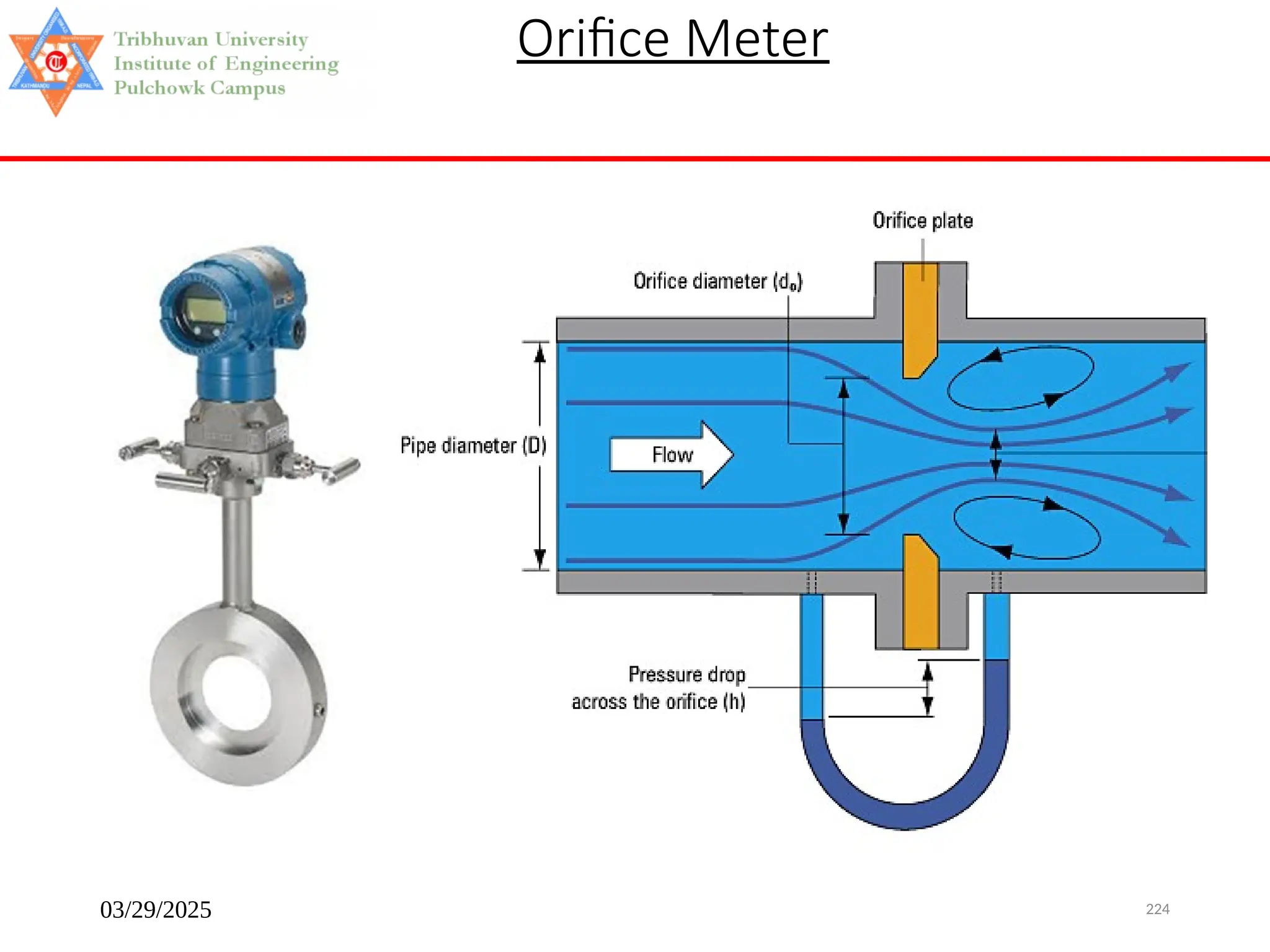
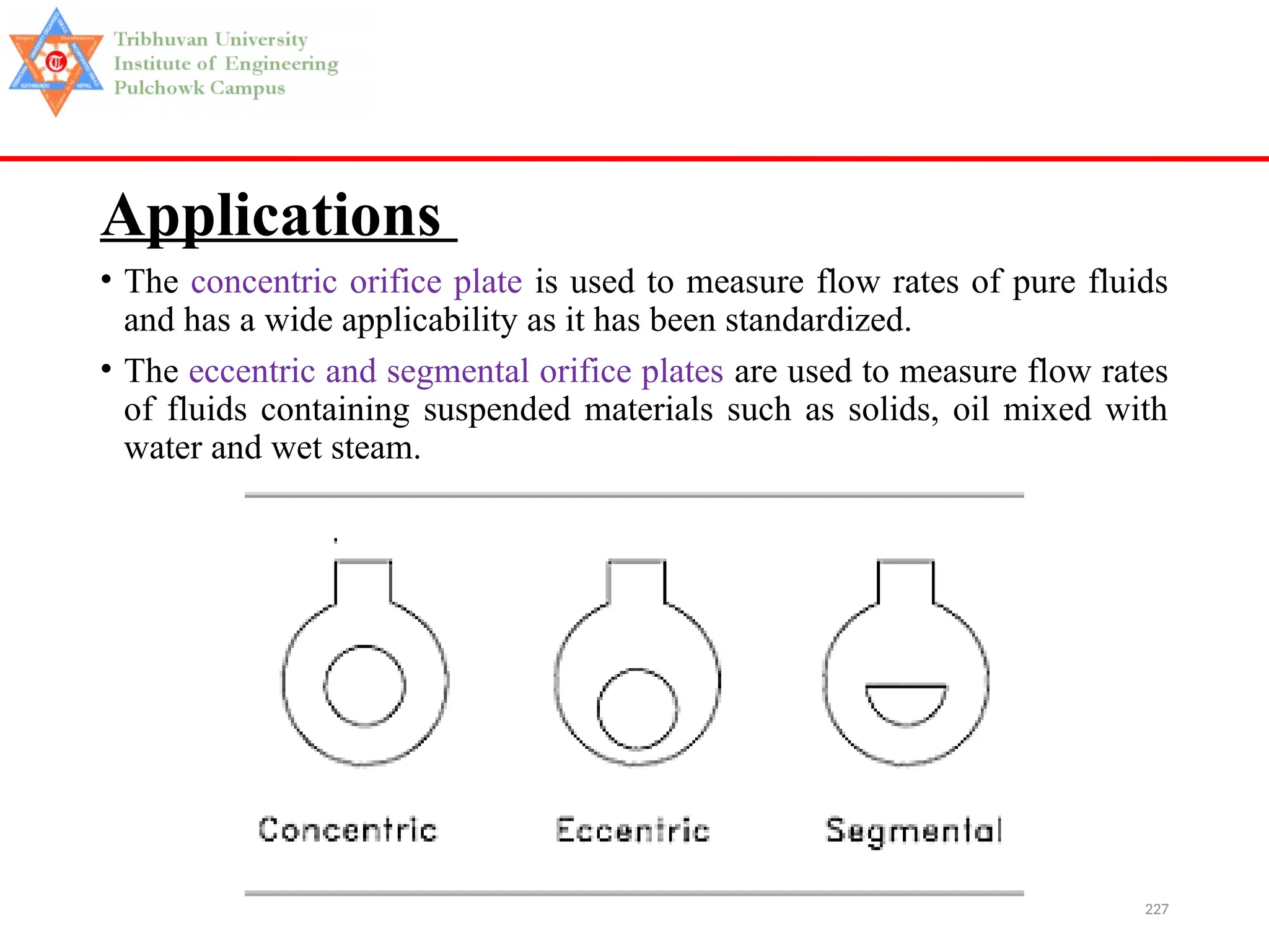
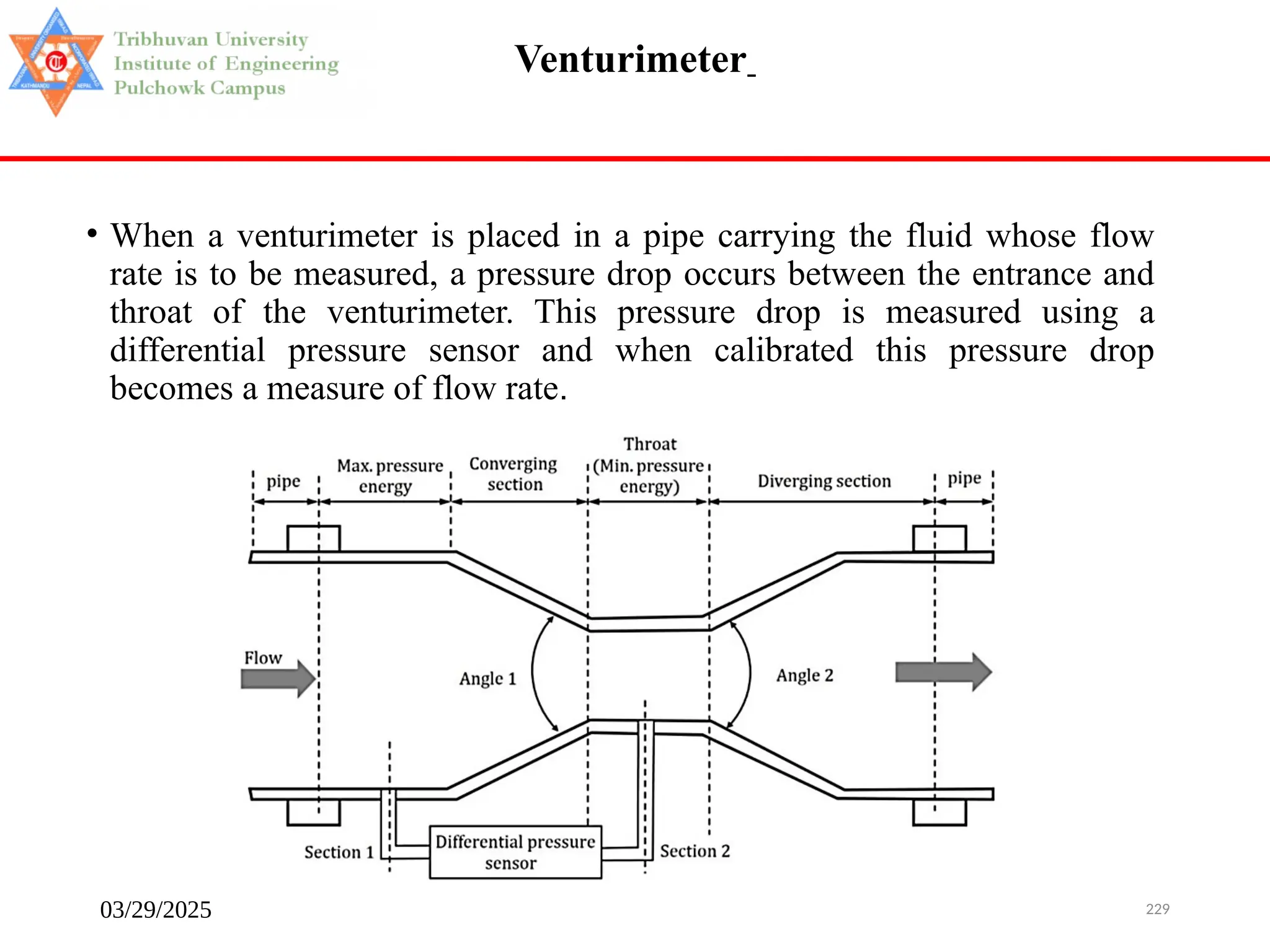
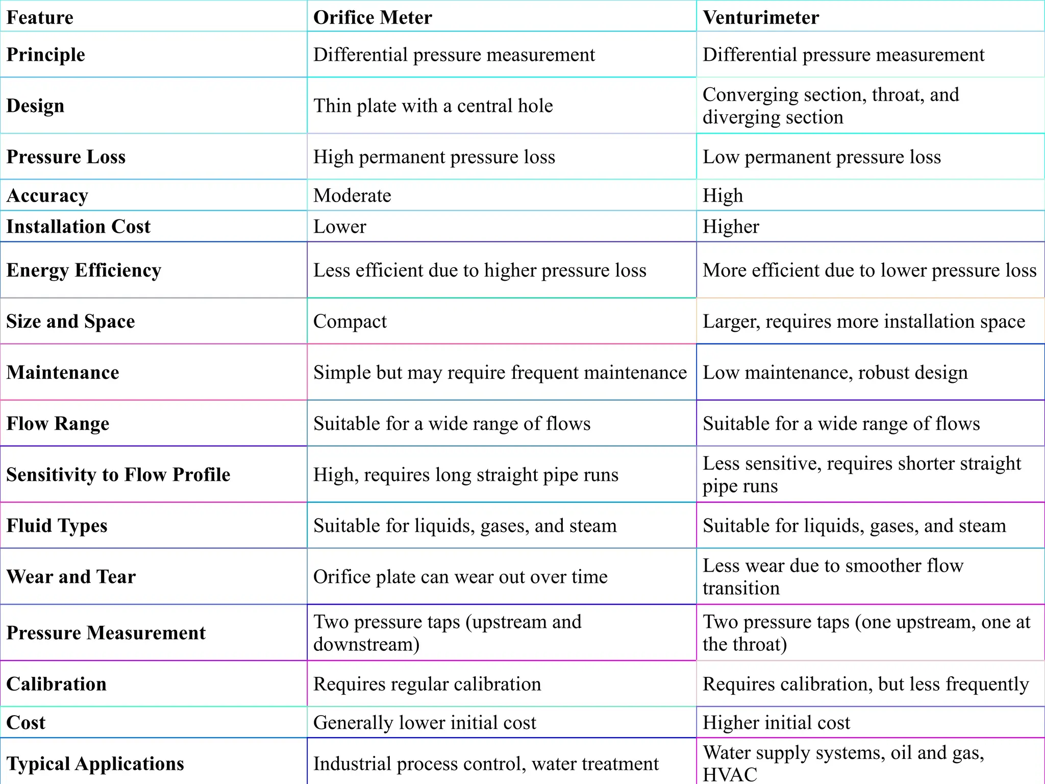
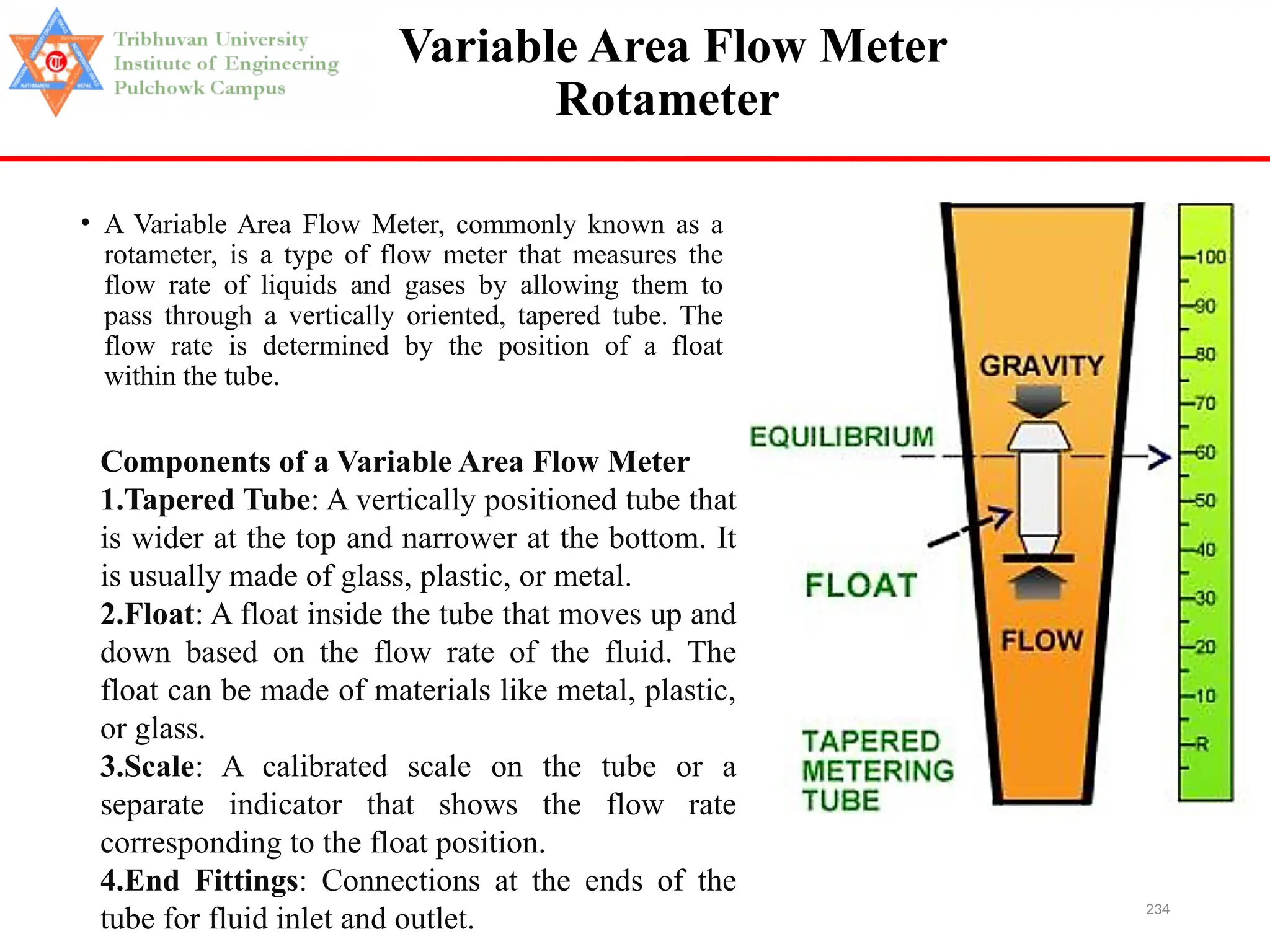
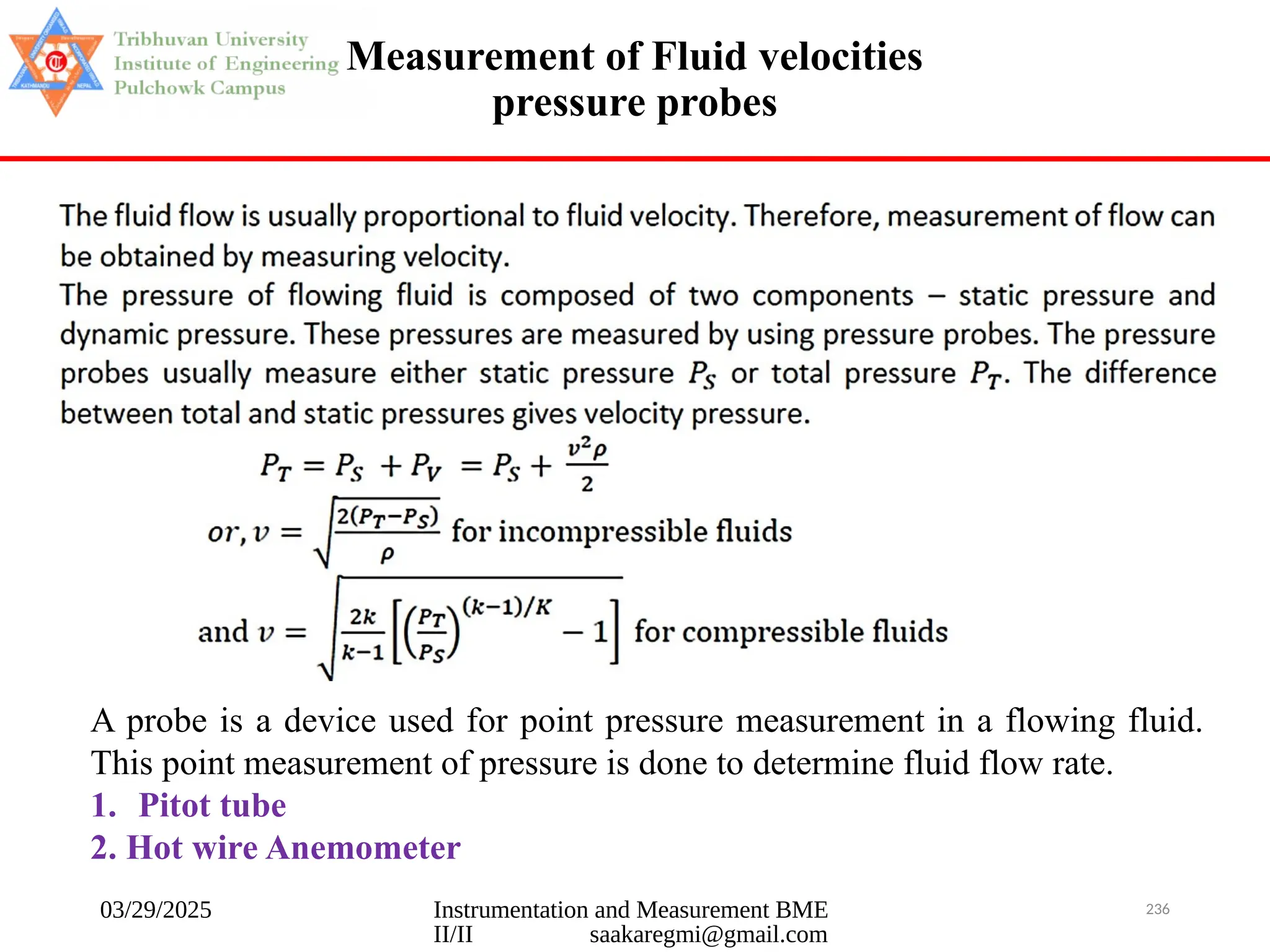
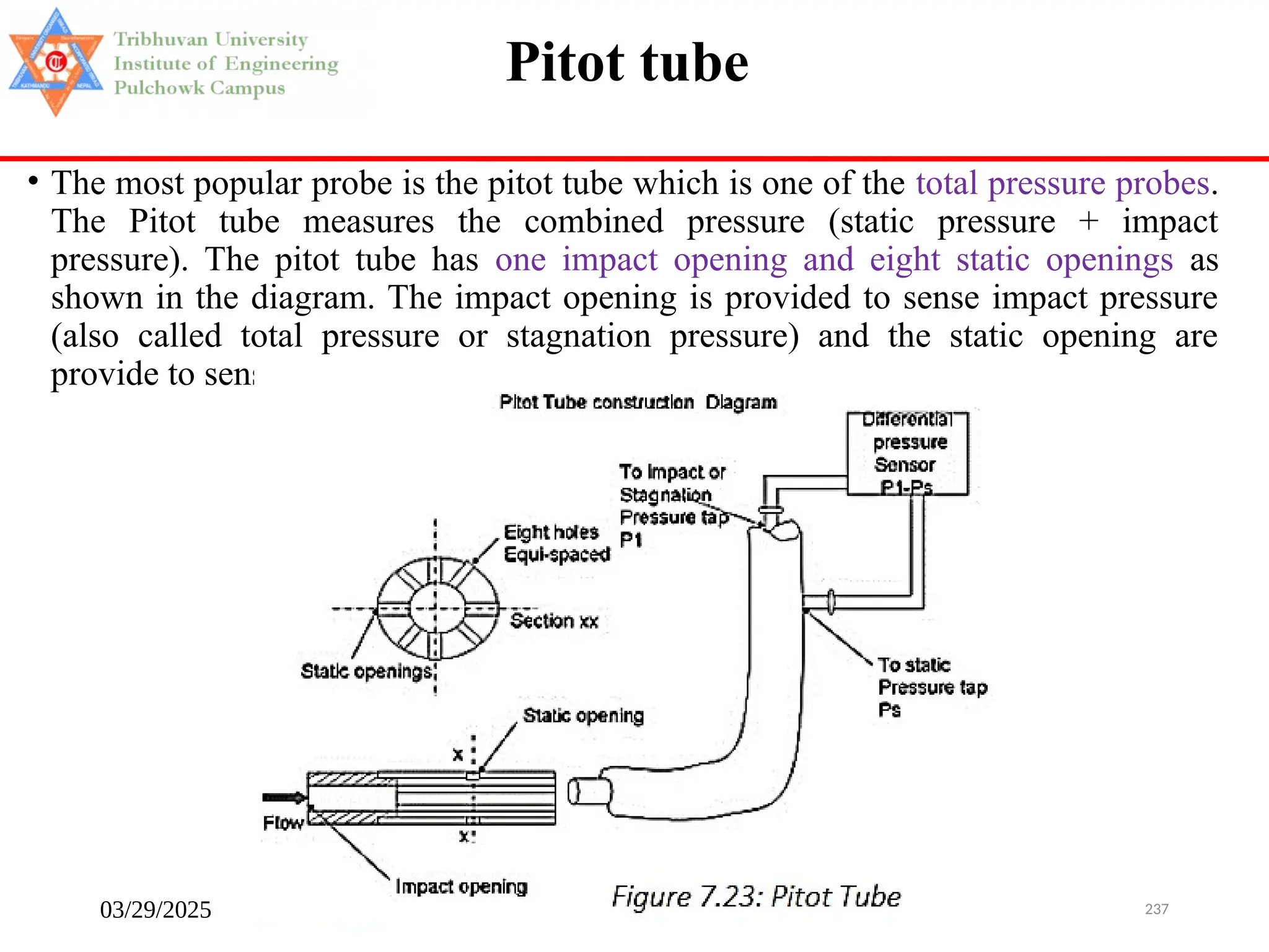
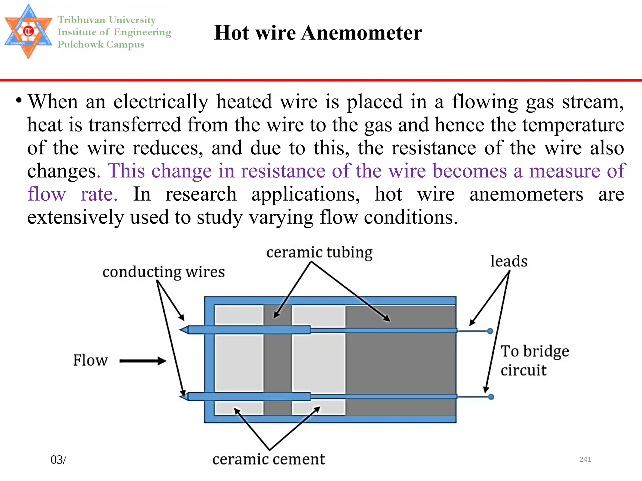
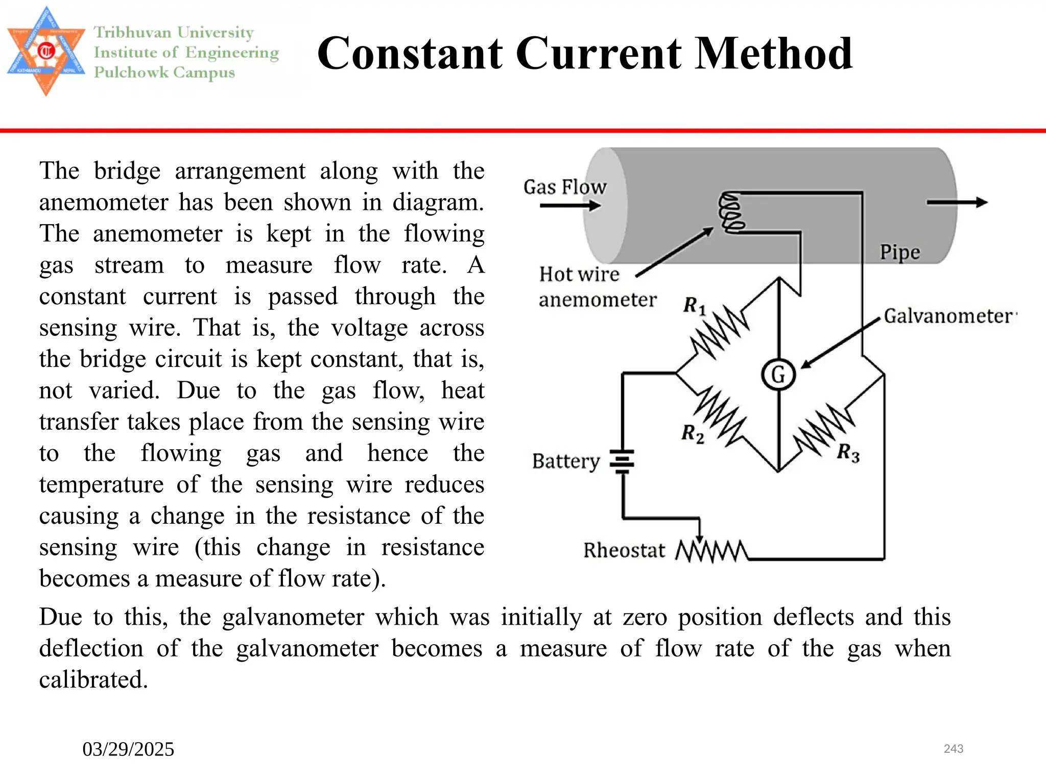
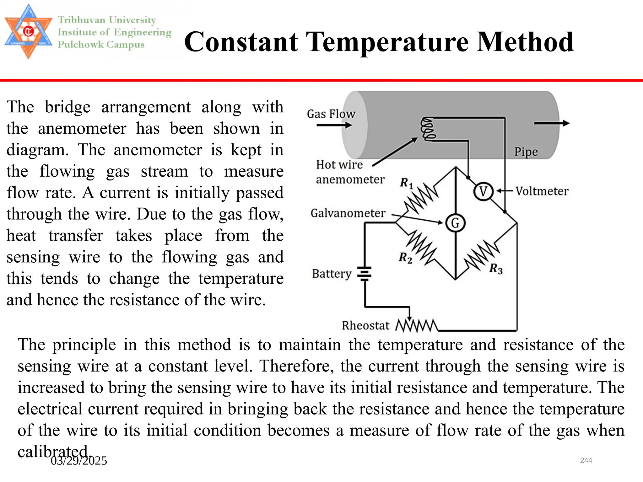
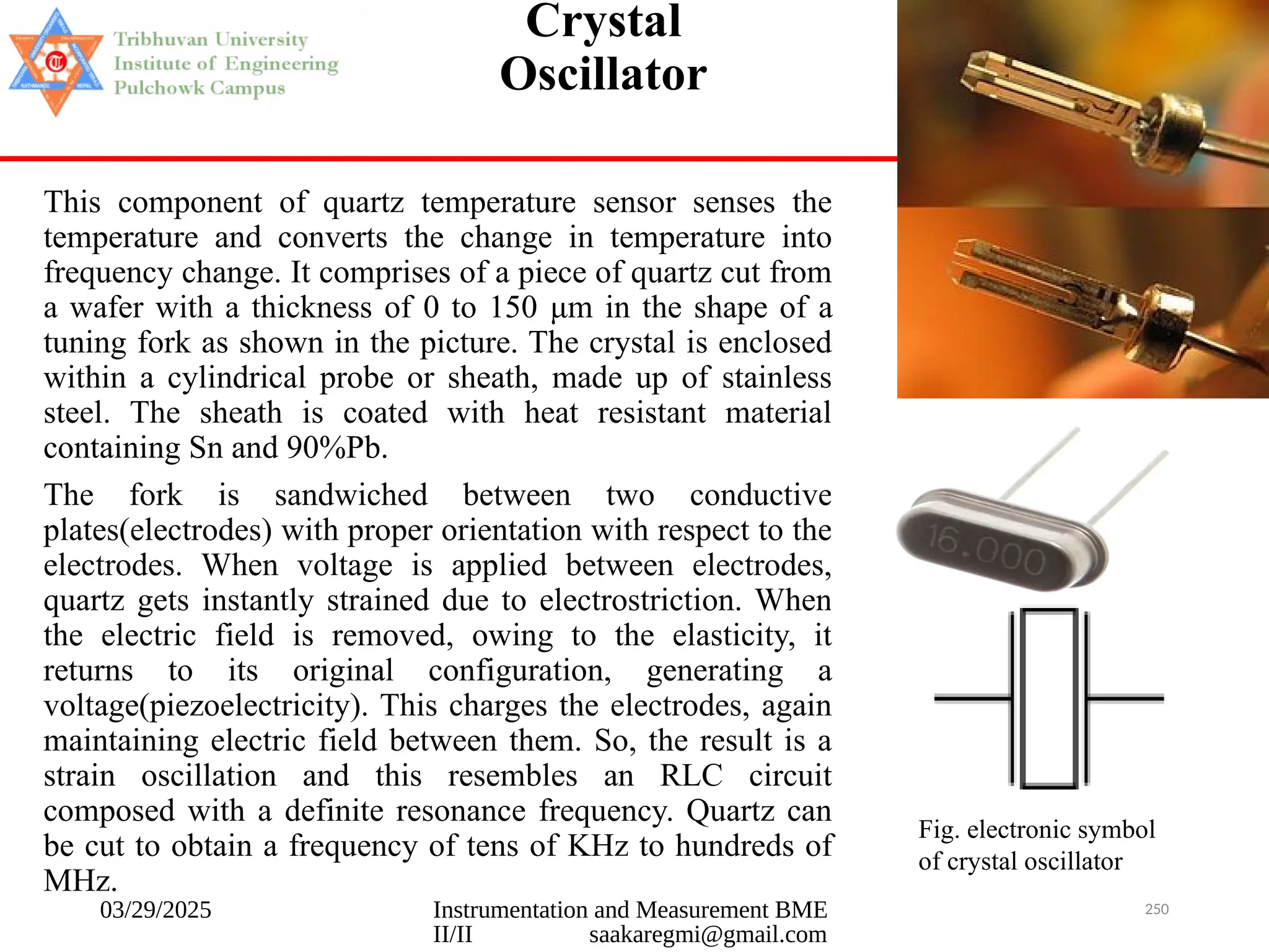
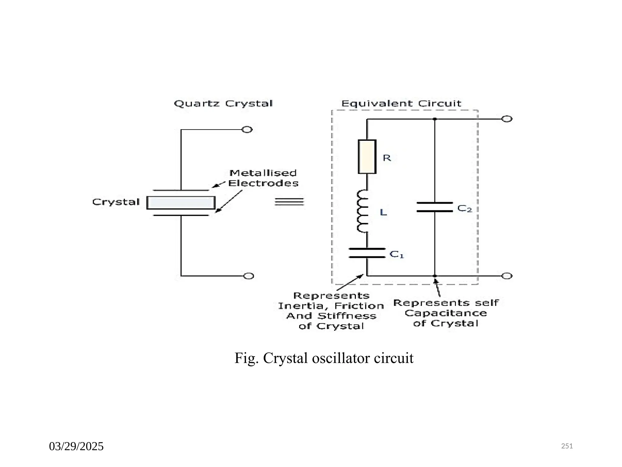
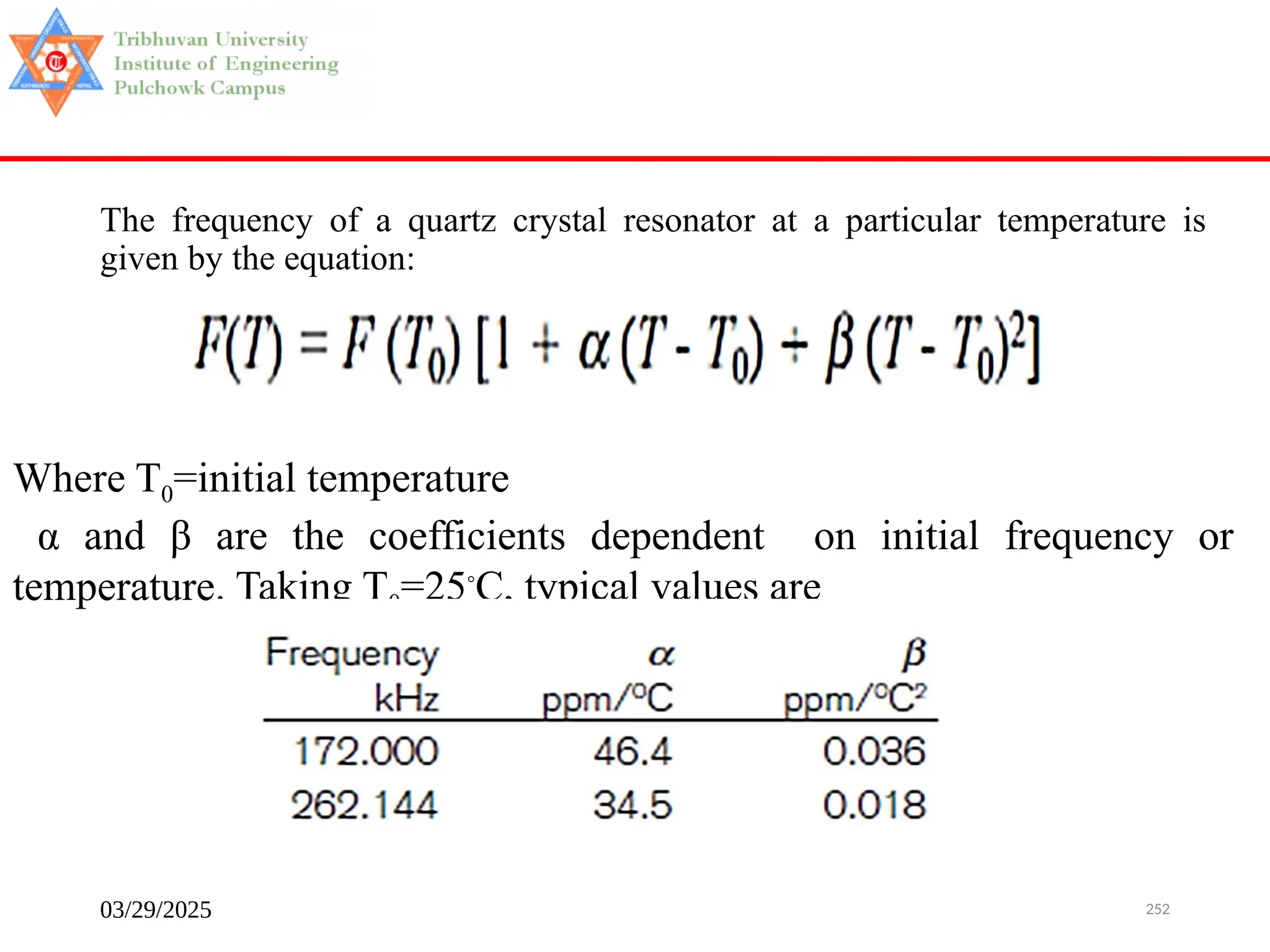
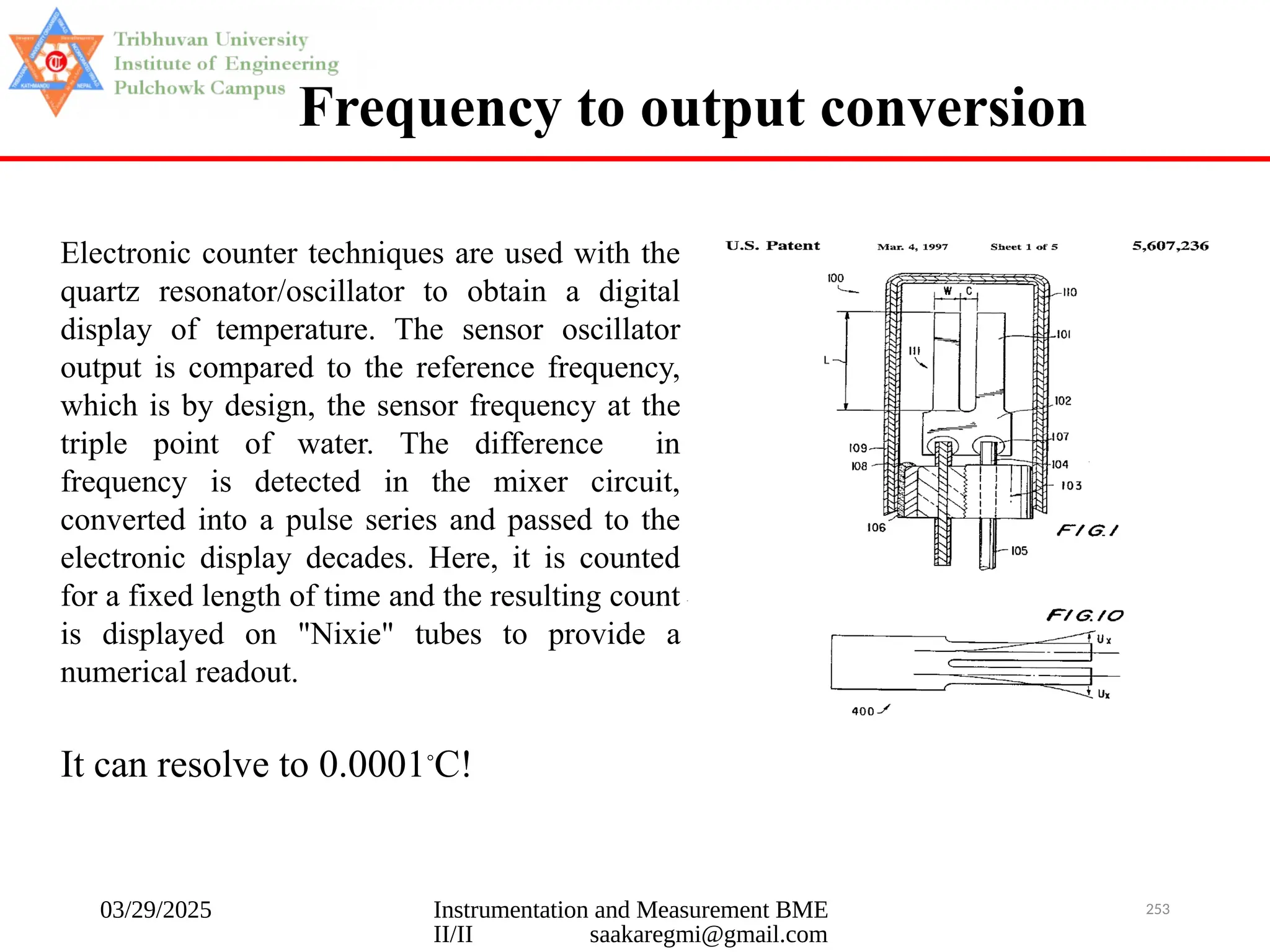
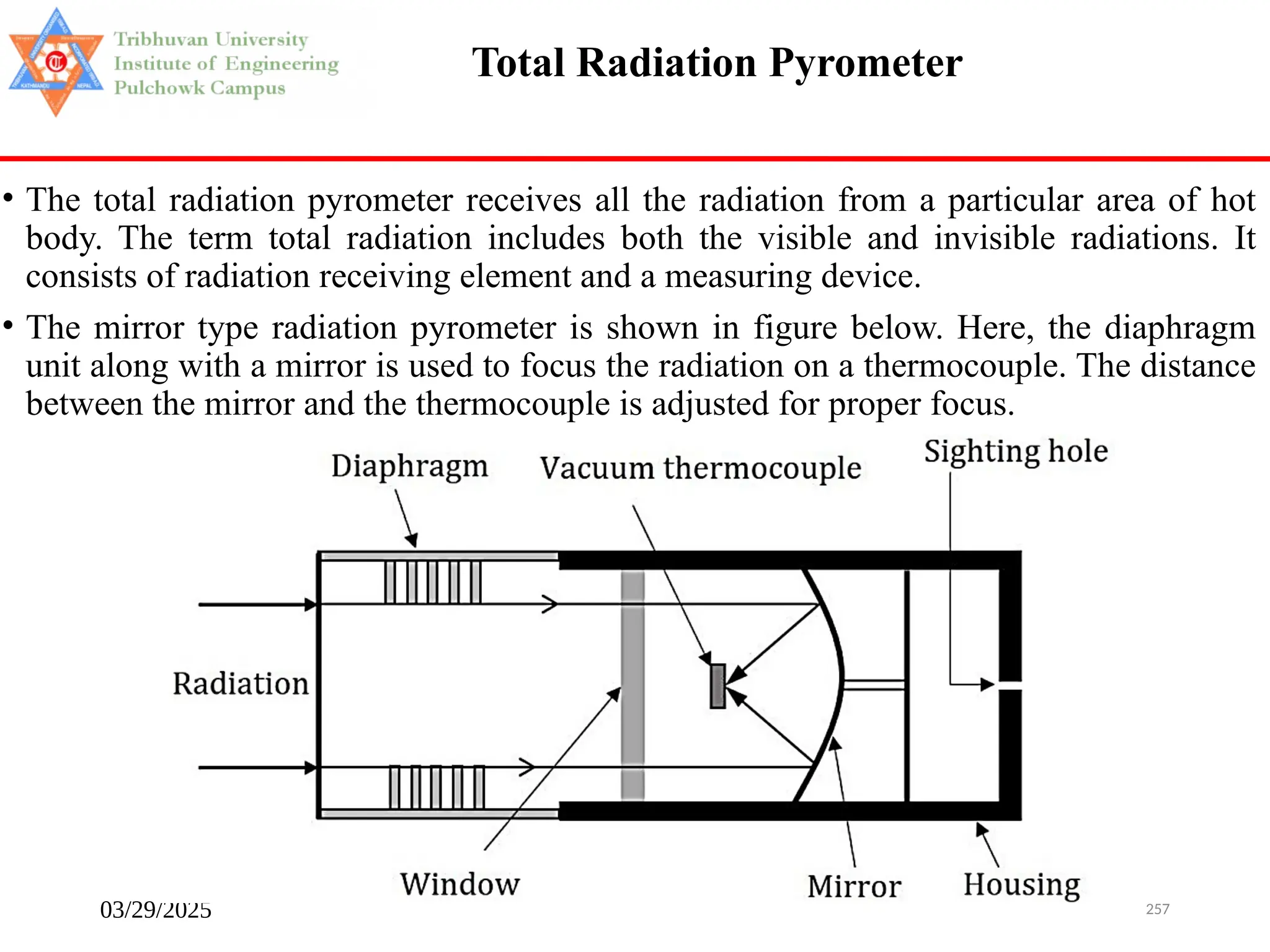
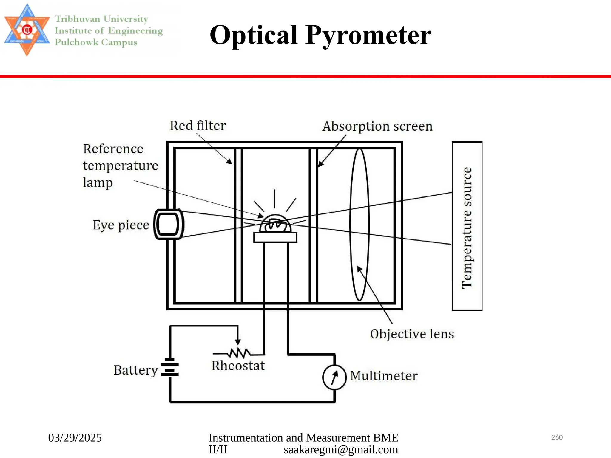
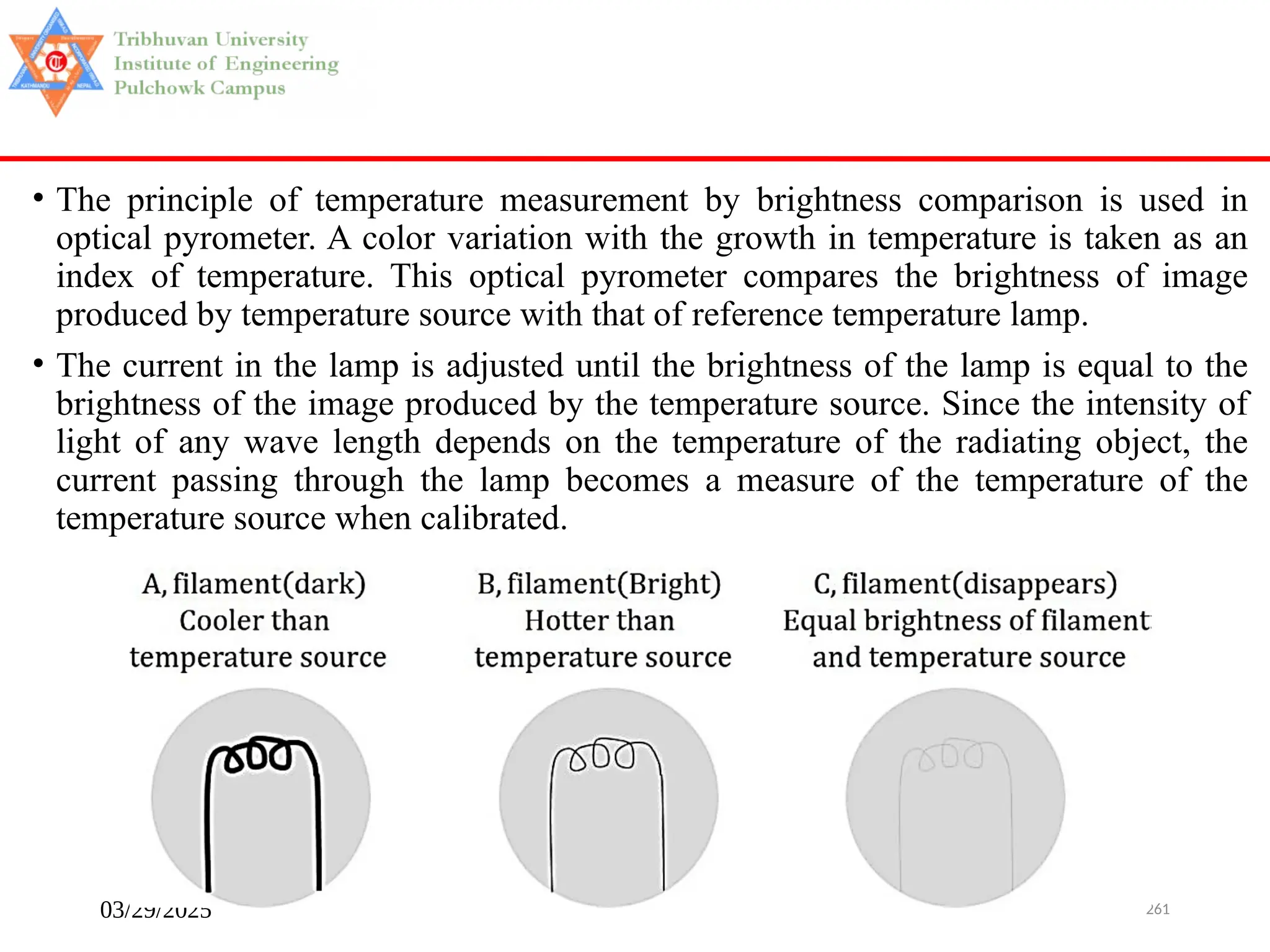
![03/29/2025 263
• When a temperature source is to be measured, the radiation from the source is
focused onto the filament of the reference temperature lamp using the objective
lens. Now the eye piece is adjusted so that the filament of the reference
temperature lamp is in sharp focus and the filament is seen super imposed on
the image of the temperature source. Now the observer starts controlling the
lamp current and the filament will appear dark as in figure (A) if the filament is
cooler than the temperature source, the filament will appear bright as in figure
(B) if the filament is hotter than the temperature source, the filament will not be
seen as in figure (C) if the filament and temperature source are in the same
temperature.
• Hence the observer should control the lamp current until the filament and the
temperature source have the same brightness which will be noticed when the
filament disappears as in figure (c) in the superimposed image of the
temperature source [ that is the brightness of the lamp and the temperature
source are same]. At the instance, the current flowing through the lamp which is
indicated by the mill voltmeter connected to the lamp becomes a measure of the
temperature of the temperature source when calibrated.
Operation](https://image.slidesharecdn.com/ioepulchowk06sensors-250329171054-46c1c0c7/75/Sensor-presentation-INSTRUMENTATION-MEASUREMENT-263-2048.jpg)