Downloaded 335 times

![2
Chapter – 1
Purpose of training and about Diesel Engine
The Purpose:
Diesel Engine
Working Principle of Diesel Engine.
Diesel Engine Process.
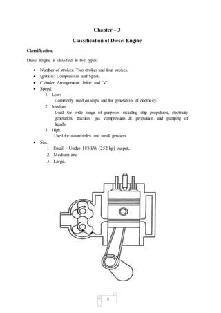
Classification of Diesel Engine.
Terminology used in Diesel Engine.
Components of Diesel Engine.
Operation of Maintenance.
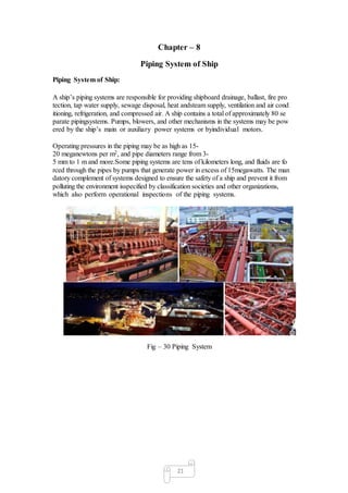
Piping System of Ship
Diesel Engine:
The diesel engine (also known as a compression-ignition engine) is an internal
combustion engine that uses the heat of compression to initiate Ignition and burn the fuel
that has been injected into the combustion chamber.
The diesel engine has the highest thermal efficiency of any standard internal or
external combustion engine due to its very high compression ratio and inherent
lean burn which enables heat dissipation by the excess air.
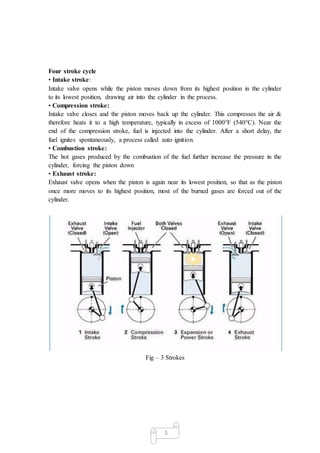
Diesel engines are manufactured in two-stroke and four-stroke versions. They
were originally used as a more efficient replacement for stationary steam engines.
The world's largest diesel engine is currently a Wärtsilä-Sulzer RTA96-C
Common Rail marine diesel of about 84.42 MW (113,210 hp) at 102 rpm[4] output.
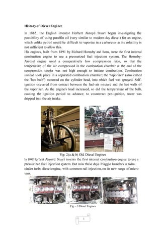
Fig: 1(a & b) Diesel Engine](https://image.slidesharecdn.com/trainingreport-141217235612-conversion-gate01/85/Training-report-on-Diesel-Engine-s-component-Engine-head-2-320.jpg)


This document provides an overview of diesel engine components and terminology. It discusses the purpose, working principle, classification, and history of diesel engines. The key components described include the engine block, crankshaft, pistons, connecting rods, cylinder liners, cylinder head, camshaft, valves, fuel system, and air system. Terminology explained includes top dead center, bottom dead center, compression ratio, indicated power, brake power, and efficiency. Piping systems of ships are also mentioned as a related topic.


