Downloaded 1,561 times


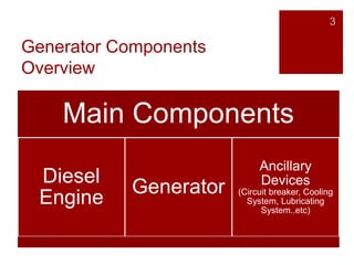
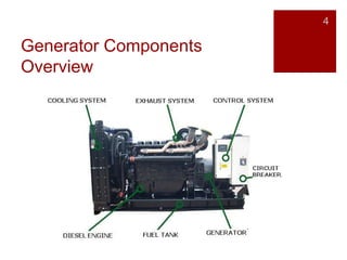
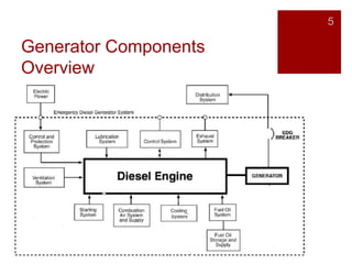


The document discusses the main components and working principle of a diesel generator. A diesel generator combines a diesel engine with an electric generator and other auxiliary devices to generate electrical energy. It works by converting the chemical energy of fuel into thermal energy, then mechanical energy through the combustion and expansion of gases in the engine, which is then converted into electrical energy through the generator via electromagnetic induction. The key components are the diesel engine, generator, and auxiliary devices like the cooling system. The diesel engine uses compression ignition to burn fuel injected into the combustion chamber.


