INTRODUCTION
Heat engine isa machine for converting heat,
developed by burning fuel into useful work. It can be said
that heat engine is equipment which generates thermal
energy and transforms it into mechanical energy.
Based on fuel used
1. Diesel engine 2. Petrol engine 3. Gas engine
Diesel engine – Diesel is used as fuel
Petrol engine – Petrol is used as fuel
Gas engines – propane, butane or methane gases are used
3.
CONSTRUCTION OF ANIC ENGINE
I.C. engine converts the reciprocating motion of piston
into rotary motion of the crankshaft by means of a
connecting rod. The piston which reciprocating in the
cylinder is very close fit in the cylinder. Rings are inserted in
the circumferential grooves of the piston to prevent leakage
of gases from sides of the piston. Usually a cylinder is bored
in a cylinder block and a gasket, made of copper sheet or
asbestos is inserted between the cylinder and the cylinder
head to avoid ant leakage. The combustion space is provided
at the top of the cylinder head where combustion takes place.
The connecting rod connects the piston and the crankshaft.
The end of the connecting rod connecting the piston is called
small end.
4.
A pin calledgudgeon pin or wrist pin is provided for
connecting the piston and the connecting rod at the small
end. The other end of the connecting rod connecting the
crank shaft is called big end. When piston is moved up and
down, the motion is transmitted to the crank shaft by the
connecting rod and the crank shaft makes rotary motion.
The crankshaft rotates in main bearings which are fitted
the crankcase. A flywheel is provided at one end of the
crankshaft for smoothing the uneven torque produced by
the engine. There is an oil sump at the bottom of the engine
which contains lubricating oil for lubricating different parts
of the engine.
5.
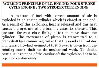
WORKING PRINCIPLE OFI.C. ENGINE/ FOUR STROKE
CYCLE ENGINE / TWO STROKE CYCLE ENGINE
A mixture of fuel with correct amount of air is
exploded in an engine cylinder which is closed at one end.
As a result of this explosion, heat is released and this heat
causes the pressure of the burning gases to increase. This
pressure forces a close fitting piston to move down the
cylinder. The movement of piston is transmitted to a
crankshaft by a connecting rod so that the crankshaft rotates
and turns a flywheel connected to it. Power is taken from the
rotating crank shaft to do mechanical work. To obtain
continuous rotation of the crankshaft the explosion has to be
repeated continuously.
6.
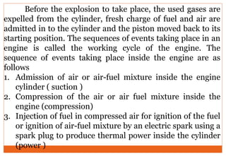
Before the explosionto take place, the used gases are
expelled from the cylinder, fresh charge of fuel and air are
admitted in to the cylinder and the piston moved back to its
starting position. The sequences of events taking place in an
engine is called the working cycle of the engine. The
sequence of events taking place inside the engine are as
follows
1. Admission of air or air-fuel mixture inside the engine
cylinder ( suction )
2. Compression of the air or air fuel mixture inside the
engine (compression)
3. Injection of fuel in compressed air for ignition of the fuel
or ignition of air-fuel mixture by an electric spark using a
spark plug to produce thermal power inside the cylinder
(power )
7.
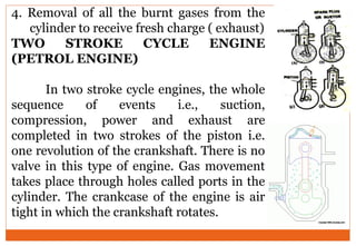
4. Removal ofall the burnt gases from the
cylinder to receive fresh charge ( exhaust)
TWO STROKE CYCLE ENGINE
(PETROL ENGINE)
In two stroke cycle engines, the whole
sequence of events i.e., suction,
compression, power and exhaust are
completed in two strokes of the piston i.e.
one revolution of the crankshaft. There is no
valve in this type of engine. Gas movement
takes place through holes called ports in the
cylinder. The crankcase of the engine is air
tight in which the crankshaft rotates.
8.
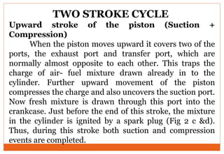
TWO STROKE CYCLE
Upwardstroke of the piston (Suction +
Compression)
When the piston moves upward it covers two of the
ports, the exhaust port and transfer port, which are
normally almost opposite to each other. This traps the
charge of air- fuel mixture drawn already in to the
cylinder. Further upward movement of the piston
compresses the charge and also uncovers the suction port.
Now fresh mixture is drawn through this port into the
crankcase. Just before the end of this stroke, the mixture
in the cylinder is ignited by a spark plug (Fig 2 c &d).
Thus, during this stroke both suction and compression
events are completed.
9.
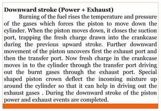
Downward stroke (Power+ Exhaust)
Burning of the fuel rises the temperature and pressure
of the gases which forces the piston to move down the
cylinder. When the piston moves down, it closes the suction
port, trapping the fresh charge drawn into the crankcase
during the previous upward stroke. Further downward
movement of the piston uncovers first the exhaust port and
then the transfer port. Now fresh charge in the crankcase
moves in to the cylinder through the transfer port driving
out the burnt gases through the exhaust port. Special
shaped piston crown deflect the incoming mixture up
around the cylinder so that it can help in driving out the
exhaust gases . During the downward stroke of the piston
power and exhaust events are completed.
10.
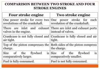
COMPARISON BETWEEN TWOSTROKE AND FOUR
STROKE ENGINES
Four stroke engine Two stroke engine
One power stroke for every two
revolutions of the crankshaft.
One power stroke for each
revolution of the crankshaft.
There are inlet and exhaust
valves in the engine.
There are inlet and exhaust ports
instead of valves.
Crankcase is not fully closed and
air tight.
Crankcase is fully closed and air
tight.
Top of the piston compresses the
charge.
Both sides of the piston compress
the charge.
Size of the flywheel is
comparatively larger.
Size of the flywheel is
comparatively smaller.
Fuel is fully consumed. Fuel is not fully consumed.
11.
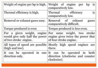
Weight of engineper hp is high. Weight of engine per hp is
comparatively low.
Thermal efficiency is high. Thermal efficiency is
comparatively low.
Removal or exhaust gases easy. Removal of exhaust gases
comparatively difficult.
Torque produced is even Torque produced is less even.
For a given weight, engine
would give only half the power
of two stroke engine.
For same weight, two stroke
engine gives twice the power that
of four stroke engine.
All types of speed are possible
(high and low).
Mostly high speed engines are
there.
It can be operated in one
direction only.
It can be operated in both
direction (clockwise and counter
clockwise).
12.
WORKING PRINCIPLE OFDIESEL ENGINE
The basic components of diesel engine are cylinder,
piston, injector, valves, connecting rod and crankshaft. In
diesel engines only air is drawn into the cylinder. The
engine has high compraession ratio hence the air in the
cylinder attains very high temperature and pressure at the
end of the compression stroke. At the end of the
compression stroke, the fuel is sprayed into the cylinder in
atomized form using injectors. Due to high temperature,
the fuel gets ignited, begins to burn and produce lot of
heat. Due to the heat the gases expand, move the piston
downward and rotate the crank shaft. The torque available
at the rotating crank shaft is used to do any mechanical
work.
13.
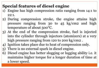
Special features ofdiesel engine
1) Engine has high compression ratio ranging from 14:1 to
22:1.
2) During compression stroke, the engine attains high
pressure ranging from 30 to 45 kg/cm2 and high
temperature of about 500°C.
3) At the end of the compression stroke, fuel is injected
into the cylinder through injectors (atomizers) at a very
high pressure ranging from 120 to 200 kg/cm2 .
4) Ignition takes place due to heat of compression only.
5) There is no external spark in diesel engine.
6) Diesel engine has better slogging or lugging ability i.e. it
maintains higher torque for a longer duration of time at
a lower speed.
14.
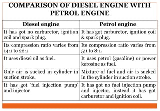
COMPARISON OF DIESELENGINE WITH
PETROL ENGINE
Diesel engine Petrol engine
It has got no carburetor, ignition
coil and spark plug.
It has got carburetor, ignition coil
& spark plug.
Its compression ratio varies from
14:1 to 22:1
Its compression ratio varies from
5:1 to 8:1.
It uses diesel oil as fuel. It uses petrol (gasoline) or power
kerosine as fuel.
Only air is sucked in cylinder in
suction stroke.
Mixture of fuel and air is sucked
in the cylinder in suction stroke.
It has got ‘fuel injection pump’
and injector
It has got no fuel injection pump
and injector, instead it has got
carburetor and ignition coil.
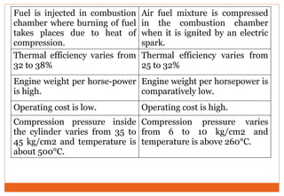
15.
Fuel is injectedin combustion
chamber where burning of fuel
takes places due to heat of
compression.
Air fuel mixture is compressed
in the combustion chamber
when it is ignited by an electric
spark.
Thermal efficiency varies from
32 to 38%
Thermal efficiency varies from
25 to 32%
Engine weight per horse-power
is high.
Engine weight per horsepower is
comparatively low.
Operating cost is low. Operating cost is high.
Compression pressure inside
the cylinder varies from 35 to
45 kg/cm2 and temperature is
about 500°C.
Compression pressure varies
from 6 to 10 kg/cm2 and
temperature is above 260°C.
16.
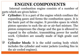
ENGINE COMPONENTS
Internal combustionengine consists of a number of
parts which are given below :
Cylinder: It is a part of the engine which confines the
expanding gases and forms the combustion space. It is
the basic part of the engine. It provides space in which
piston operates to suck the air or air-fuel mixture. The
piston compresses the charge and the gas is allowed to
expand in the cylinder, transmitting power for useful
work. Cylinders are usually made of high grade cast
iron.
Cylinder block: It is the solid casting body which
includes the cylinder and water jackets (cooling fins in
the air cooled engines).
17.
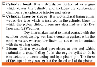
Cylinder head:It is a detachable portion of an engine
which covers the cylinder and includes the combustion
chamber, spark plugs or injector and valves.
Cylinder liner or sleeve: It is a cylindrical lining either
wet or dry type which is inserted in the cylinder block in
which the piston slides. Liners are classified as : (1) Dry
liner and (2) Wet liner.
Dry liner makes metal to metal contact with the
cylinder block casing. wet liners come in contact with the
cooling water, whereas dry liners do not come in contact
with the cooling water.
Piston: It is a cylindrical part closed at one end which
maintains a close sliding fit in the engine cylinder. It is
connected to the connecting rod by a piston pin. The force
of the expanding gases against the closed end of the piston,
18.
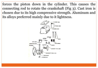
forces the pistondown in the cylinder. This causes the
connecting rod to rotate the crankshaft (Fig 3). Cast iron is
chosen due to its high compressive strength. Aluminum and
its alloys preferred mainly due to it lightness.
19.
Engine components
Head (Crown)of piston: It is the top of the piston.
Skirt: It is that portion of the piston below the piston pin
which is designed to adsorb the side movements of the
piston.
Piston ring: It is a split expansion ring, placed in the
groove of the piston. They are usually made of cast iron
or pressed steel alloy (Fig.3). The function of the ring are
as follows :
It forms a gas tight combustion chamber for all
positions of piston.
It reduces contact area between cylinder wall and
piston wall preventing friction losses and excessive
wear.
20.
It controlsthe cylinder lubrication.
It transmits the heat away from the piston to the
cylinder walls.
Piston rings are of two types: (1) Compression ring
and (2) Oil ring
Compression ring
Compression rings are usually plain, single piece
and are always placed in the grooves of the piston
nearest to the piston head. They prevent leakage of
gases from the cylinder and helps increasing
compression pressure inside the cylinder.
21.
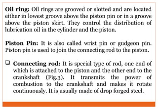
Oil ring: Oilrings are grooved or slotted and are located
either in lowest groove above the piston pin or in a groove
above the piston skirt. They control the distribution of
lubrication oil in the cylinder and the piston.
Piston Pin: It is also called wrist pin or gudgeon pin.
Piston pin is used to join the connecting rod to the piston.
Connecting rod: It is special type of rod, one end of
which is attached to the piston and the other end to the
crankshaft (Fig.3). It transmits the power of
combustion to the crankshaft and makes it rotate
continuously. It is usually made of drop forged steel.
22.
Crankshaft: Itis the main shaft of an engine which
converts the reciprocating motion of the piston into
rotary motion of the flywheel (Fig.3). Usually the
crankshaft is made of drop forged steel or cast steel.
The space that supports the crankshaft in the cylinder
block is called main journal, whereas the part to
which connecting rod is attached is known as crank
journal. Crankshaft is provided with counter weights
throughout its length to have counter balance of the
unit.
23.
Flywheel: Flywheelis made of cast iron. Its main
functions are as follows :
It stores energy during power stroke and returns
back the energy during the idle strokes, providing a
uniform rotary motion of flywheel.
The rear surface of the flywheel serves as one of the
pressure surfaces for the clutch plate.
Engine timing marks are usually stamped on the
flywheel, which helps in adjusting the timing of the
engine.
Sometime the flywheel serves the purpose of a pulley
for transmitting power.
24.
Crankcase: Thecrankcase is that part of the engine
which supports and encloses the crankshaft and
camshaft. It provides a reservoir for the lubricating oil.
It also serves as a mounting unit for such accessories as
the oil pump, oil filter,, starting motor and ignition
components. The upper portion of the crankcase is
usually integral with cylinder block. The lower part of
the crankcase is commonly called oil pan and is usually
made of cast iron or cast aluminum.
Camshaft: It is a shaft which raises and lowers the
inlet and exhaust valves at proper times. Camshaft is
driven by crankshaft by means of gears, chains or
sprockets (Fig3). The speed of the camshaft is exactly
half the speed of the crankshaft in four stroke engine.
25.
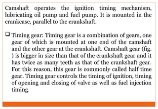
Camshaft operates theignition timing mechanism,
lubricating oil pump and fuel pump. It is mounted in the
crankcase, parallel to the crankshaft.
Timing gear: Timing gear is a combination of gears, one
gear of which is mounted at one end of the camshaft
and the other gear at the crankshaft. Camshaft gear (fig.
) is bigger in size than that of the crankshaft gear and it
has twice as many teeth as that of the crankshaft gear.
For this reason, this gear is commonly called half time
gear. Timing gear controls the timing of ignition, timing
of opening and closing of valve as well as fuel injection
timing.
26.
Inlet manifold: Itis that part of the engine through
which air or air-fuel mixture enters into the engine
cylinder. It is fitted by the side of the cylinder head.
Exhaust manifold: It is that part of the engine
through which exhaust gases go out of the engine
cylinder. It is capable of withstanding high temperature
of burnt gases. It is fitted by the side of the cylinder
head.
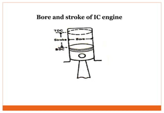
Top dead centre - When the piston is at the top of its
stroke, it is said to be at the top dead centre (TDC),
Bottom dead centre - when the piston is at the
bottom of its stroke, it is said to be at its bottom dead
centre (BDC).
27.
In two strokecycle engine both the sides of the
piston are effective which is not the case in four stroke
cycle engine.
Scavenging
The process of removal of burnt or exhaust gases
from the engine cylinder is known as scavenging. Entire
burnt gases do not go out in normal stroke, hence some
type of blower or compressor is used to remove the
exhaust gases in two stroke cycle engine.
28.
TERMINOLOGY CONNECTED WITH
ENGINEPOWER
• Bore- Bore is the diameter of the engine cylinder.
• Stroke - It is the linear distance traveled by the piston
from Top dead centre (TDC) to Bottom dead centre
(BDC).
• Stroke-bore ratio -The ratio of length of stroke (L)
and diameter of bore (D) of the cylinder is called stroke-
bore ratio (L/D). In general, this ratio varies between 1
to 1.45 and for tractor engines, this ratio is about 1.25.
• Swept volume - It is the volume (A x L) displaced by
one stroke of the piston where A is the cross sectional
area of piston and L is the length of stroke (Fig.4).