Downloaded 1,158 times
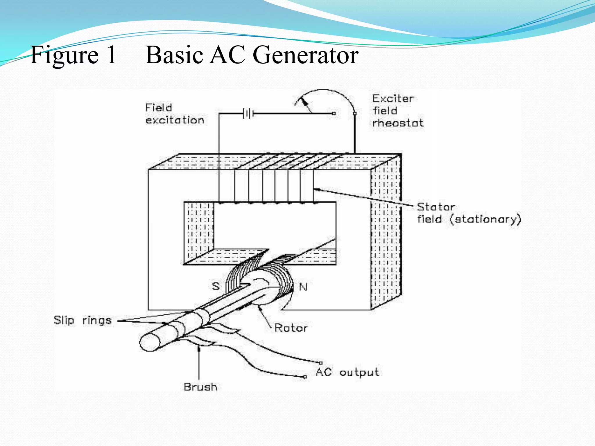
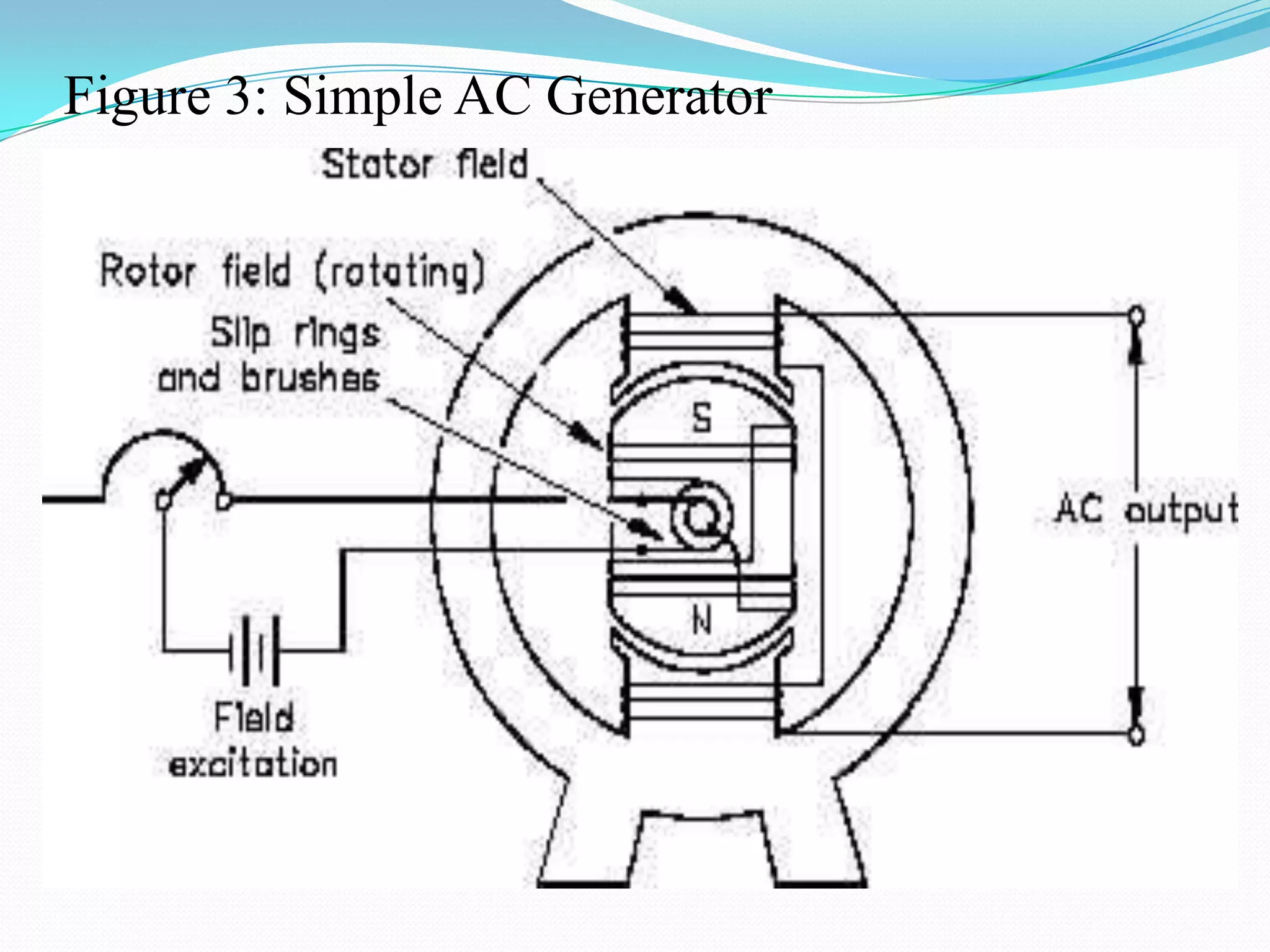

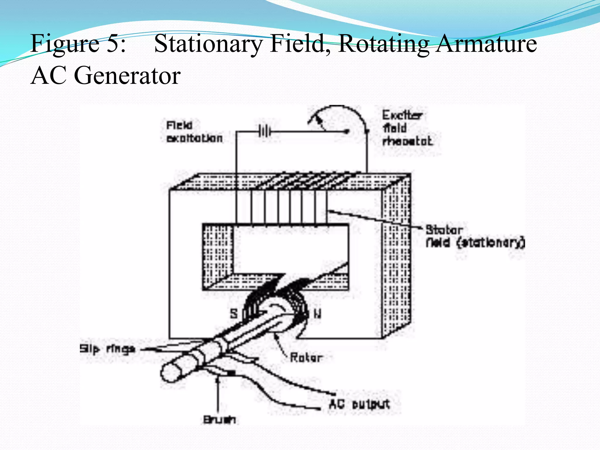

The document describes the key components and operation of an AC generator. It includes: - The main components are the field, armature, prime mover, rotor, stator, and slip rings. The rotor and stator can each be the field or armature depending on the generator type. - In operation, the prime mover rotates the rotor through the stationary field, inducing voltage in the armature windings. Slip rings allow a continuous connection to the rotating armature. - Losses occur from internal resistance, hysteresis in the iron cores, and mechanical factors like bearing friction. Efficiency is the ratio of output to input power. Generators are rated by voltage, current, power


