Downloaded 651 times
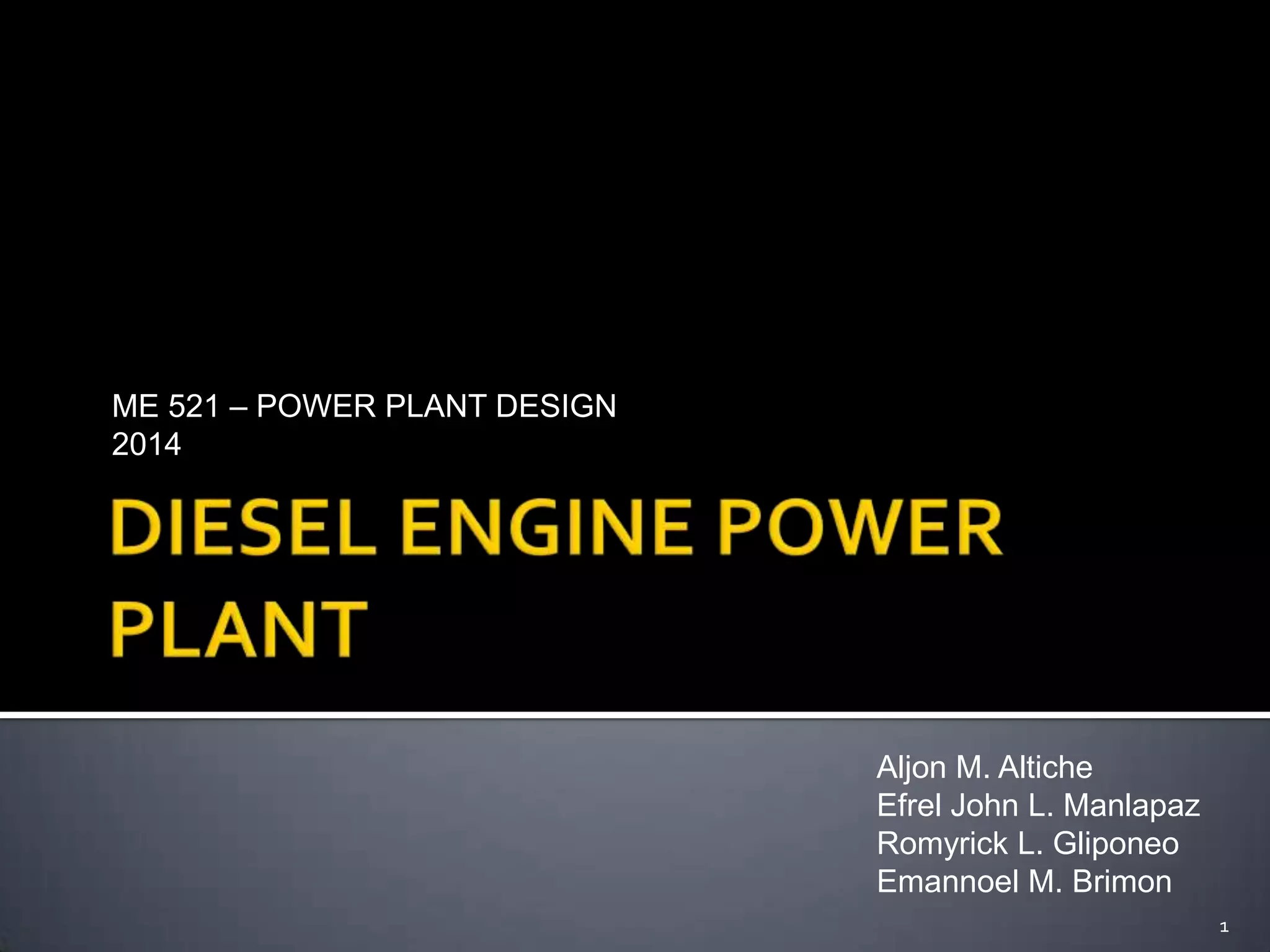


![OPERATION PROCEDURES
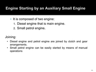
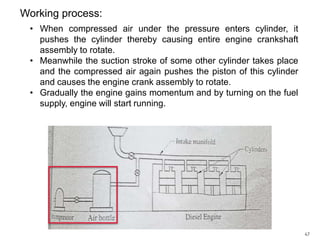
Pre-Operation Procedures
Verify order of operation with Shift Supervisor On-duty prior to carrying out prestartup procedures.
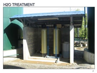
Visually check the Jacket Water [JW] and Injector Cooling [IC] Water
expansion tanks for proper level.
Check inlet and outlet valves of Nozzle and Jacket Waters systems for proper
open or close positions.
Press JW and NC water pumps start button located on the Engine Control
Panel [ECP].
Energize JW and IC water heaters by pressing the “ON” button located on the
Heaters Control Panel [HCP].
Check the level of the various engine tanks and auxiliary equipment.
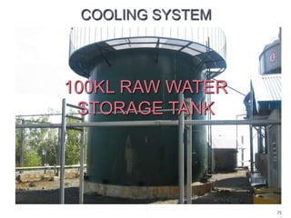
Cooling Tower Pond
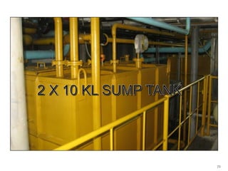
Oil Sump Tank
Cylinder Lubricating Oil Tank
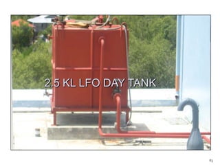
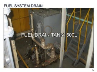
Bunker fuel service and settling tank
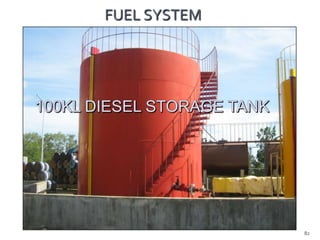
Diesel storage tanks
Turbocharger oil level
Governor oil level
Outboard bearing oil level
Air pressure for 30 and 8 bar tanks
94](https://image.slidesharecdn.com/dieselenginereport-140208103037-phpapp02/85/Diesel-engine-report-94-320.jpg)
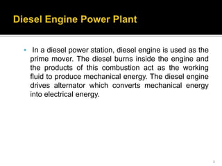
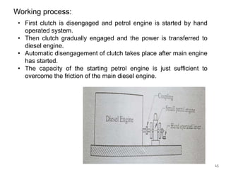
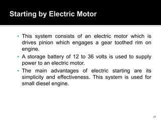
![Start-Up Procedure
Energize main power supply for the engine alarm.
Start up the following and adjust the pressures:
Pre-lubricating oil pump (manual position)
Diesel transfer pump
Fuel booster module
Nozzle cooling water pump
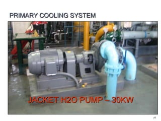
Jacket water pump
Fuel service pump
Check that the turning gear is disengaged and that the operating lever is locked.
Open all the indicator cocks.
Check starting air tank pressure gauge for the proper pressure of 25 to 30 bar.
Set the governor load limit to “0” position, and rotate the speed setting knob for at
least five [5] revolutions from zero.
Set the governor speed droop to “40” position.
Move each individual fuel pump rack in and out a few times to ensure rack is free
and not binding.
Press the emergency stop button.
Open the starting air valve.
Get clearance and “GO” signal with Shift Supervisor On-duty for startup activation.
96](https://image.slidesharecdn.com/dieselenginereport-140208103037-phpapp02/85/Diesel-engine-report-96-320.jpg)


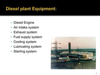
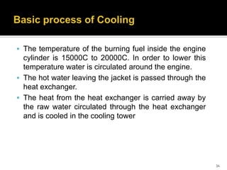
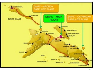
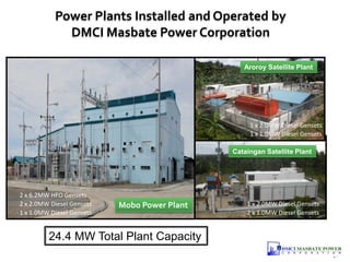
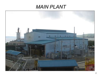
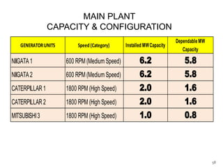
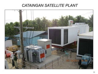
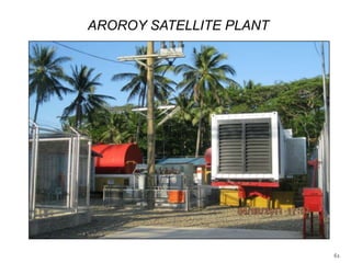
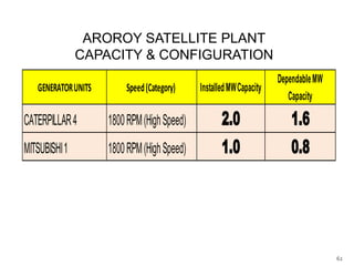
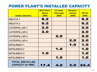
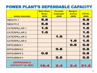
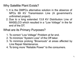
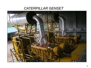
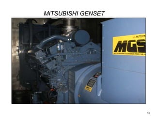
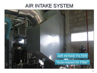
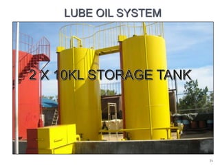
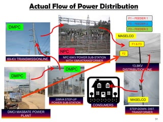
This document provides information about a diesel power plant design course and diesel power plants. It discusses the basic components and workings of diesel engines and power plants, including the engine, air intake and exhaust systems, fuel supply system, cooling system, lubricating system, and starting system. It then summarizes specific diesel power plants operated by DMCI Masbate Power Corporation on Masbate Island, Philippines, including their installed and dependable capacities, generator configurations, and reasons for having satellite plants in addition to the main plant.


![[PPT] on Steam Turbine](https://cdn.slidesharecdn.com/ss_thumbnails/spsharmafinalppt-140608082156-phpapp01-thumbnail.jpg?width=640&height=640&fit=bounds)


