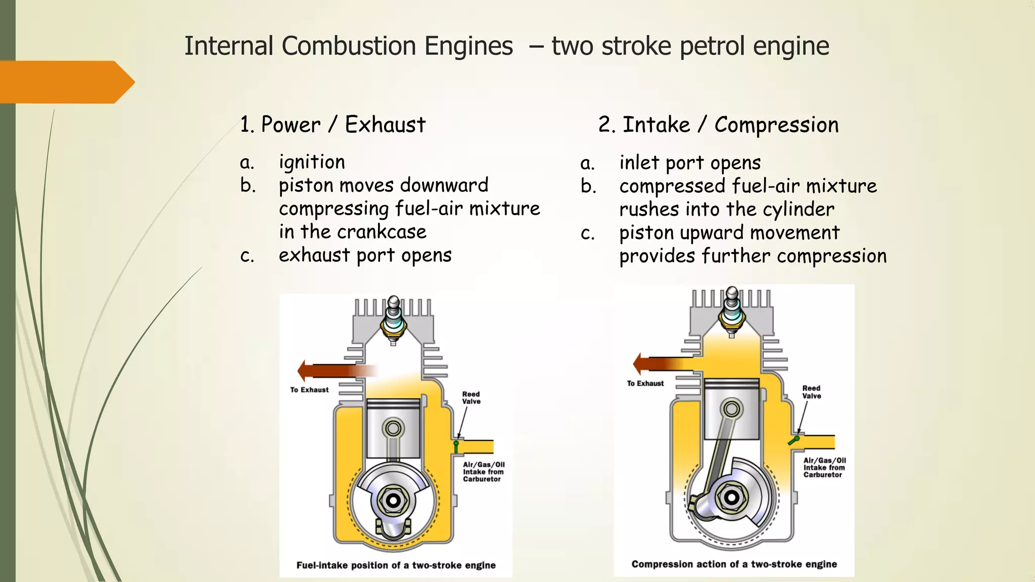
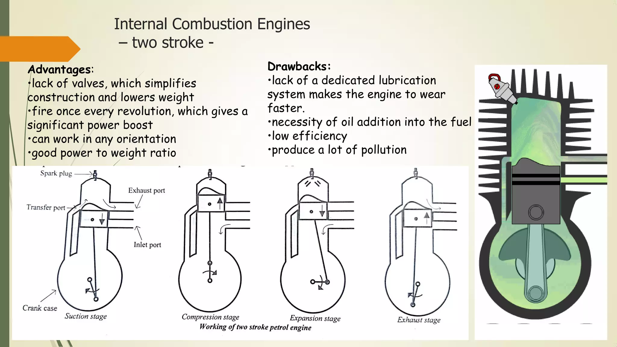
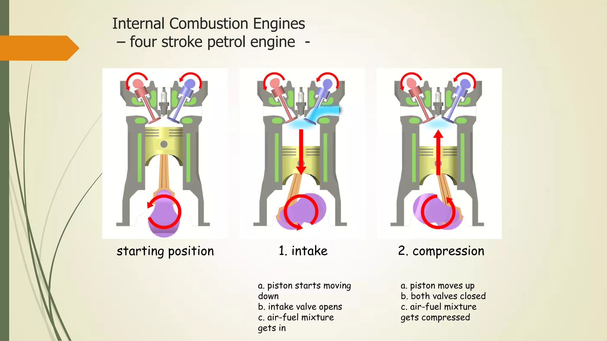
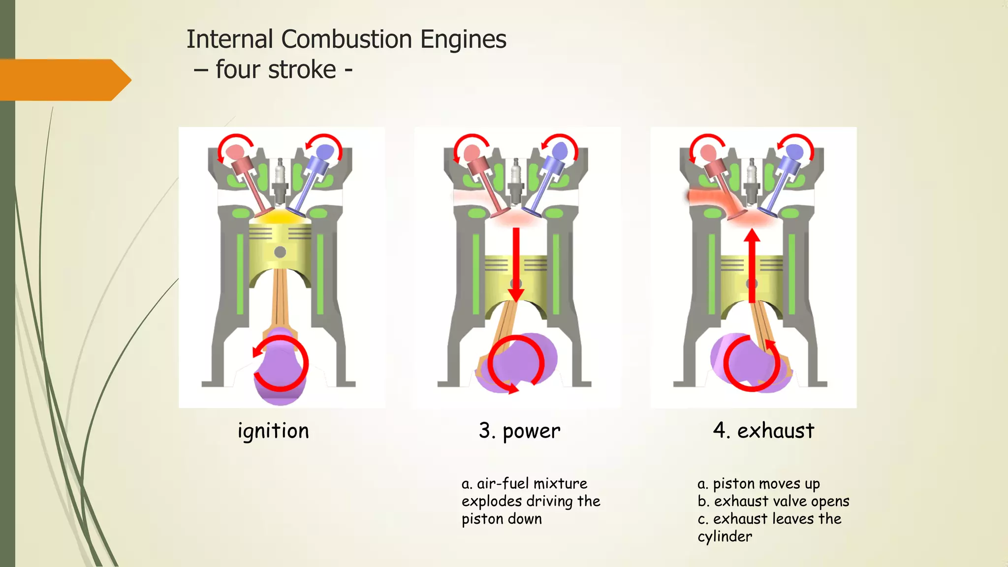
The document provides a comprehensive overview of automotive engineering, including the classification and components of engines, types of vehicles, fuel properties, and power transmission systems. It discusses internal combustion engines, their construction, and various ignition types, as well as features of two-stroke and four-stroke engines. Additionally, it covers transmission methods like belt, chain, and gear drives, detailing their mechanics and applications in automobiles.


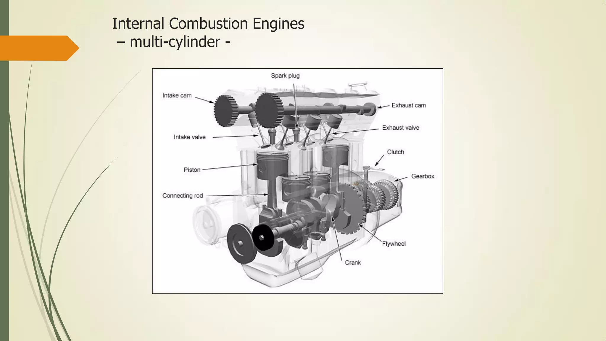


![SBP- IC Engines [Compatibility Mode] (1).pdf](https://cdn.slidesharecdn.com/ss_thumbnails/sbp-icenginescompatibilitymode1-241227102120-3fc3e41a-thumbnail.jpg?width=640&height=640&fit=bounds)


