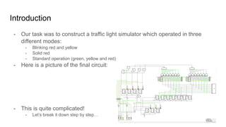
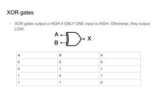
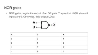
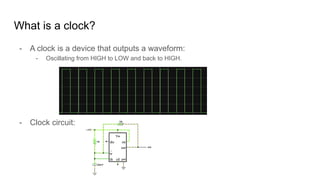
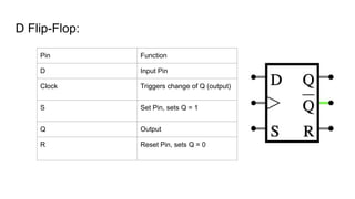
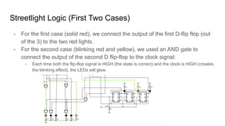
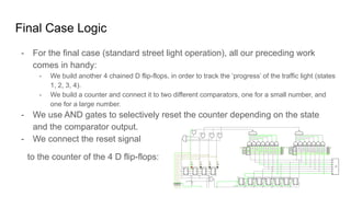
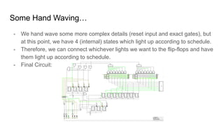
Traffic Light Final Project
By Ali El Moselhy,
Sandy Shan,
and Peter He
Table of Contents:
- Introduction
- What is a Circuit?
- What are Logic Gates?
- What are Binary Numbers?
- What is a Comparator?
- What is a Clock?
- What are Flip-Flops?
- Putting it all together…
Introduction
- Our task was to construct a traffic light simulator which operated in three
different modes:
- Blinking red and yellow
- Solid red
- Standard operation (green, yellow and red)
- Here is a picture of the final circuit:
- This is quite complicated!
- Let’s break it down step by step…
What is a Circuit?
- Circuits use a difference in voltage to extract work.
- Electricity moves from high to low voltages, and that movement allows us to do ‘things’
- A Light Emitting Diode (LED) glows when electricity runs through it.
- When referring to circuits:
- “HIGH” = “1” = “high potential” = “on”
- “LOW” = “0” = “low potential” = “off”
What are Logic Gates?
- Logic Gates are the foundation of all modern circuits.
- Logic Gates take in multiple inputs, and output a single HIGH or LOW signal.
- There are 7 main types of logic gates:
- Inverter
- AND
- OR
- XOR
- NAND
- NOR
- XNOR
- We used 4 of these gate types.
AND gates
- AND gates output HIGH if both inputs are HIGH. Otherwise, they output LOW:
A B X
0 0 0
0 1 0
1 0 0
1 1 1
OR gates
- OR gates output HIGH if any input is HIGH. Otherwise, they output LOW:
A B X
0 0 0
0 1 1
1 0 1
1 1 1
XOR gates
- XOR gates output a HIGH if ONLY ONE input is HIGH. Otherwise, they output
LOW:
A B X
0 0 0
0 1 1
1 0 1
1 1 0
NOR gates
- NOR gates negate the output of an OR gate. They output HIGH when all
inputs are 0. Otherwise, they output LOW:
A B X
0 0 1
0 1 0
1 0 0
1 1 0
Binary Numbers
- Binary numbers are numbers stored in a format that the computer can
understand:
- How can we differentiate between 0, 1, 2, … 8, 9? We can’t…
- We DO have values of either 0 or 1, so we can use a system of binary numbers.
- Each place value in a binary number represents a power of two:
1101 = 1 + 4 + 8 = 13
1st place
value: 1*20
3rd place
value: 1*22
4th place
value: 1*23
2nd place
value: 0*21
What is a comparator?
- Some quick recall:
- An XOR gate only activates when the inputs are different e.g. 1 and 0, or 0
and 1.
- Therefore, if an XOR gate outputs 0, we know the two inputs must be the
same, either both 0’s or 1’s.
- With a NOR gate, we can use this feature to compare two binary numbers:
What is a clock?
- A clock is a device that outputs a waveform:
- Oscillating from HIGH to LOW and back to HIGH.
- Clock circuit:
What are Flip-Flops?
- Flip-flops are devices which act as basic memory - they can store a single bit
each.
- Two main types (that we used):
- J-K flip-flops - used in our counter.
- D-flip flops - used for general memory.
- Both types of Flip-Flops activate on a signal edge:
D Flip-Flop:
Pin Function
D Input Pin
Clock Triggers change of Q (output)
S Set Pin, sets Q = 1
Q Output
R Reset Pin, sets Q = 0
JK Flip-Flop:
Pin Function
J, K Input Pins
Clock Triggers change of Q (output)
Q Output
R Reset Pin, sets Q=0
JK Flip-Flop Behavior
- The behavior of JK flip-flops is quite complicated:
- The most useful thing to us is the behavior when both J and K are one: the
chip toggles back and forth between 0 and 1.
Counters
- Think of counting in binary:
0, 1, 10, 11, 100, 101, 110, 111, 1000…
- We examine the 3rd digit.
- It only changes on the digits highlighted in blue, and each time before the change, the
preceding digits are 1 (highlighted in red)
- To be more precise, for any digit to change when counting in binary, all preceding digits need
to be 1’s.
- We can use this idea to build a counter which operates off of a clock.
Counters
- Here is a synchronous counter (clock signals are simultaneous between each
flip-flop):
- Each digit only changes (toggles) when every preceding digit is 1. (We read
left as the smallest digit, and right as the largest digit.)
- Connecting together the Reset inputs of each flip flop allows us to reset the
entire counter with a single input.
Chained D Flip-Flops
- We handle the ‘chosen’ states as follows:
- Initialize 3 chained D flip-flops in a 1-0-0 format, and connect a button to the
clock input of each:
This construction causes a HIGH signal to propagate through the flip flops each
time we hit the switch.
Streetlight Logic (First Two Cases)
- For the first case (solid red), we connect the output of the first D-flip flop (out
of the 3) to the two red lights.
- For the second case (blinking red and yellow), we used an AND gate to
connect the output of the second D flip-flop to the clock signal:
- Each time both the flip-flop signal is HIGH (the state is correct) and the clock is HIGH (creates
the blinking effect), the LEDs will glow.
Final Case Logic
- For the final case (standard street light operation), all our preceding work
comes in handy:
- We build another 4 chained D flip-flops, in order to track the ‘progress’ of the traffic light (states
1, 2, 3, 4).
- We build a counter and connect it to two different comparators, one for a small number, and
one for a large number.
- We use AND gates to selectively reset the counter depending on the state
and the comparator output.
- We connect the reset signal
to the counter of the 4 D flip-flops:
Some Hand Waving…
- We hand wave some more complex details (reset input and exact gates), but
at this point, we have 4 (internal) states which light up according to schedule.
- Therefore, we can connect whichever lights we want to the flip-flops and have
them light up according to schedule.
- Final Circuit:

Traffic Light.pdf

  • 1.
    Traffic Light FinalProject By Ali El Moselhy, Sandy Shan, and Peter He
  • 2.
    Table of Contents: -Introduction - What is a Circuit? - What are Logic Gates? - What are Binary Numbers? - What is a Comparator? - What is a Clock? - What are Flip-Flops? - Putting it all together…
  • 3.
    Introduction - Our taskwas to construct a traffic light simulator which operated in three different modes: - Blinking red and yellow - Solid red - Standard operation (green, yellow and red) - Here is a picture of the final circuit: - This is quite complicated! - Let’s break it down step by step…
  • 4.
    What is aCircuit? - Circuits use a difference in voltage to extract work. - Electricity moves from high to low voltages, and that movement allows us to do ‘things’ - A Light Emitting Diode (LED) glows when electricity runs through it. - When referring to circuits: - “HIGH” = “1” = “high potential” = “on” - “LOW” = “0” = “low potential” = “off”
  • 5.
    What are LogicGates? - Logic Gates are the foundation of all modern circuits. - Logic Gates take in multiple inputs, and output a single HIGH or LOW signal. - There are 7 main types of logic gates: - Inverter - AND - OR - XOR - NAND - NOR - XNOR - We used 4 of these gate types.
  • 6.
    AND gates - ANDgates output HIGH if both inputs are HIGH. Otherwise, they output LOW: A B X 0 0 0 0 1 0 1 0 0 1 1 1
  • 7.
    OR gates - ORgates output HIGH if any input is HIGH. Otherwise, they output LOW: A B X 0 0 0 0 1 1 1 0 1 1 1 1
  • 8.
    XOR gates - XORgates output a HIGH if ONLY ONE input is HIGH. Otherwise, they output LOW: A B X 0 0 0 0 1 1 1 0 1 1 1 0
  • 9.
    NOR gates - NORgates negate the output of an OR gate. They output HIGH when all inputs are 0. Otherwise, they output LOW: A B X 0 0 1 0 1 0 1 0 0 1 1 0
  • 10.
    Binary Numbers - Binarynumbers are numbers stored in a format that the computer can understand: - How can we differentiate between 0, 1, 2, … 8, 9? We can’t… - We DO have values of either 0 or 1, so we can use a system of binary numbers. - Each place value in a binary number represents a power of two: 1101 = 1 + 4 + 8 = 13 1st place value: 1*20 3rd place value: 1*22 4th place value: 1*23 2nd place value: 0*21
  • 11.
    What is acomparator? - Some quick recall: - An XOR gate only activates when the inputs are different e.g. 1 and 0, or 0 and 1. - Therefore, if an XOR gate outputs 0, we know the two inputs must be the same, either both 0’s or 1’s. - With a NOR gate, we can use this feature to compare two binary numbers:
  • 12.
    What is aclock? - A clock is a device that outputs a waveform: - Oscillating from HIGH to LOW and back to HIGH. - Clock circuit:
  • 13.
    What are Flip-Flops? -Flip-flops are devices which act as basic memory - they can store a single bit each. - Two main types (that we used): - J-K flip-flops - used in our counter. - D-flip flops - used for general memory. - Both types of Flip-Flops activate on a signal edge:
  • 14.
    D Flip-Flop: Pin Function DInput Pin Clock Triggers change of Q (output) S Set Pin, sets Q = 1 Q Output R Reset Pin, sets Q = 0
  • 15.
    JK Flip-Flop: Pin Function J,K Input Pins Clock Triggers change of Q (output) Q Output R Reset Pin, sets Q=0
  • 16.
    JK Flip-Flop Behavior -The behavior of JK flip-flops is quite complicated: - The most useful thing to us is the behavior when both J and K are one: the chip toggles back and forth between 0 and 1.
  • 17.
    Counters - Think ofcounting in binary: 0, 1, 10, 11, 100, 101, 110, 111, 1000… - We examine the 3rd digit. - It only changes on the digits highlighted in blue, and each time before the change, the preceding digits are 1 (highlighted in red) - To be more precise, for any digit to change when counting in binary, all preceding digits need to be 1’s. - We can use this idea to build a counter which operates off of a clock.
  • 18.
    Counters - Here isa synchronous counter (clock signals are simultaneous between each flip-flop): - Each digit only changes (toggles) when every preceding digit is 1. (We read left as the smallest digit, and right as the largest digit.) - Connecting together the Reset inputs of each flip flop allows us to reset the entire counter with a single input.
  • 19.
    Chained D Flip-Flops -We handle the ‘chosen’ states as follows: - Initialize 3 chained D flip-flops in a 1-0-0 format, and connect a button to the clock input of each: This construction causes a HIGH signal to propagate through the flip flops each time we hit the switch.
  • 20.
    Streetlight Logic (FirstTwo Cases) - For the first case (solid red), we connect the output of the first D-flip flop (out of the 3) to the two red lights. - For the second case (blinking red and yellow), we used an AND gate to connect the output of the second D flip-flop to the clock signal: - Each time both the flip-flop signal is HIGH (the state is correct) and the clock is HIGH (creates the blinking effect), the LEDs will glow.
  • 21.
    Final Case Logic -For the final case (standard street light operation), all our preceding work comes in handy: - We build another 4 chained D flip-flops, in order to track the ‘progress’ of the traffic light (states 1, 2, 3, 4). - We build a counter and connect it to two different comparators, one for a small number, and one for a large number. - We use AND gates to selectively reset the counter depending on the state and the comparator output. - We connect the reset signal to the counter of the 4 D flip-flops:
  • 22.
    Some Hand Waving… -We hand wave some more complex details (reset input and exact gates), but at this point, we have 4 (internal) states which light up according to schedule. - Therefore, we can connect whichever lights we want to the flip-flops and have them light up according to schedule. - Final Circuit: