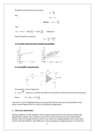
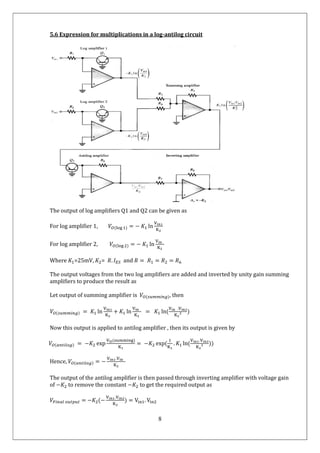
Electronics
National
Analog
UNDER THE GUIDANCE OF
DR. KOUSIK GUHA SIR AND DR
DEPT OF ELECTRONICS AND COMMUNICATION
NIT SILCHAR
1
Department of
Electronics and Communication Engineering
ational Institute of Technology
2020
Analog IC and Technology
Mini Project
Submitted By:
Name - RAN SHER
Scholar ID - 1814110
Branch – ECE -B
DR. BRINDA BHOWMICK MA’AM,
COMMUNICATION ENGINEERING,
Engineering
Technology, Silchar
2
Log-Antilog Single Quardant Multipliers
RAN SHER (1814110), B.Tech(5th sem)
Department of Electronics and Communiction Engineering
National Institute of Technology, Silchar
ransherraj@gmail.com
ABSTRACT
Log-antilog amplifiers are excellent devices to perform the mathematical operations like multiplication,
division and exponentiation just like in computers. This is the theoretical study of the Log and antilog
single quadrant multipliers. The approach is to theoretically identify the characteristics and behavior
of Log and antilog multipliers and show how they are extremely important in producing errorless
multiplication.
TABLE OF CONTENTS
Introduction……………………………………2
Multiplier Quadrants…………………………..3
Log amplifiers…………………………………3
Anti-log amplifiers…..………………………...4
Log-Antilog……..……………………………...6
Results and Discussion…………………….......9
Applications……………………………………9
Conclusions…………………………………….9
Acknowledgement……………………………...9
References……………………………………..10
1. INTRODUCTION
Log and Antilog amplifiers are non-linear circuits in which the output voltage is proportional to the
logarithm (or exponent) of the input. The log and antilog amplifiers together can be utilized to produce
log-antilog multipliers. It is well known that some processes such as multiplication and
division which can be performed by addition and subtraction of logs.
Log amplifiers produces the output voltage which is proportional to the natural logarithm of the
applied input voltage whereas antilog amplifier, is an electronic circuit that produces an output that is
proportional to the natural anti-logarithm of the applied input. Hence the output produced by two log
amplifiers when added and passed through an anti-log amplifier produces a voltage, which is equal to
product of the voltages applied at the two log amplifiers. Hence log and antilog amplifiers together can
be used for development of log-antilog multipliers.
In single quadrant log antilog multipliers, the applied input voltages to the log amplifiers is of single
polarity and the final output produced is also of single polarity.
3
2. MULTIPLIER QUADRANTS
From a mathematical point of view, multiplication is a "four quadrant" operation—that is to say that
both inputs may be either positive or negative, as may be the output. Some of the circuits used to
produce electronic multipliers, however, are limited to signals of one polarity. If both signals must be
unipolar, we have a "single quadrant" multiplier, and the output will also be unipolar. If one of the
signals is unipolar, but the other may have either polarity, the multiplier is a "two quadrant"
multiplier, and the output may have either polarity (and is "bipolar"). The circuitry used to produce
one- and two-quadrant multipliers may be simpler than that required for four quadrant multipliers,
and since there are many applications where full four quadrant multiplication is not required, it is
common to find accurate devices which work only in one or two quadrants.
3. LOG AMPLIFIERS
A logarithmic amplifier, or a log amplifier, is an electronic circuit that produces an output that is
proportional to the logarithm of the applied input voltage. These amplifiers are used to produce the log
term when input voltages are passed through it. The important significance of log amplifiers is that
addition of two log values gives out a single log with product of two input voltages. In log circuits,
logging elements (diode or transistor) are directly connected to the output terminal of the log circuits.
Some characteristics of log amplifiers-
 Linear graph: voltage gain is very high for low input voltages and very low for high input voltages
 Semi logarithmic graph: straight line proves logarithmic nature of amplifier’s transfer
characteristics.
 Transfer characteristics of log amps are usually expressed in terms of slope of 𝑉 versus 𝑉 plot in
mili-volts per decode.
 η affects slope of transfer curve; 𝐼 determines the y intercept.
Log amplifiers can be designed in two way-
1. Log amplifiers using diode
2. Log amplifiers using transistor
3.1 Log amplifier using diode
4
Using KCL and basic theory of op amp,
I =
And
I = − I
Hence, I = −
And
𝑉 = −𝑉 = −ηV ln = −V ln taking η=1
Diode resistance is given by,
𝑟 = =
3.2 Transfer characteristics of diode log amplifier
3.3 Log amplifier using transistor
For transistor, current is given by,
𝐼 = 𝐼 𝑒 where 𝐼 is emitter saturation current and 𝑉 is drop across emitter-base junction
Hence , 𝑉 = 𝑉 = 𝑉 ln
Transistor is used as logging element in log amp which allows operation of log amplifiers over
wider current ranges hence it is called as transdiode configuration.
4. ANTI-LOG AMPLIFIERS
Antilog amplifiers are the amplifiers whose output is proportional to the natural antilog of the
applied input voltage. These amplifiers are used to remove the log term and and develop the
product of the two voltage elements which is our main aim. Antilog amplifiers have nearly same
circuit as the log amplifiers, only difference is the arrangement of logging element. In contrast to
5
log amplifiers, in antilog amplifiers, logging element is directly connected with input voltage
element. Constant parameters can be added or removed just by using inverting amplifiers of
suitable gain factor. Hence after taking log inputs to antilog, some constant element is produced
which is removed by using suitable inverting amplifiers.
Similar to log amplifiers, antilog amplifiers can be designed in two ways.
1. With diode logging element.
2. With transdiode logging element.
4.1 Anti-Log Amplifiers with diode as logging element
Output voltage is given by
𝑉 = −𝑅 𝐼 𝑒
4.2 Anti-Log Amplifiers with transdiode(transistor) as logging element
Output voltage is given by
𝑉 = −𝑅 𝐼 𝑒
Same as the log amplifiers, it is necessary to know saturation currents for the determination of
output voltages in anti-log amplifiers. It is require to tightly control junction temperature as with
increase in temperature, there will be increases the thermal voltages and alter in the resistance of
the logging element and hence it may happen to get errors in calculations of output voltages.
Temperature can be controlled by using temperature compensation circuits.
6
5. LOG – ANTILOG
Log - antilog amplifier circuits includes the same elements but arranged with exactly opposite
feedback configuration. Some integrated log amplifiers have uncommitted elements allowing user
to implement antilog amplifiers.
Some IC like ICL8049 are committed only for antilog amplifiers. Some are called as multifunction
converters like AD538, LH0094, 4302 etc. includes operational amplifiers(op amps) and
transistors to simultaneously implement log and antilog functions, or functions derived from it
such as
 multiplication,
 division,
 raising to a power,
 taking a root etc.
5.1 Multiplication stages in log-antilog multipliers
 First step is to get logarithm of the input voltages applied at log amplifiers.
𝑉 = ln 𝑉
and
𝑉 = ln 𝑉
where 𝑉 and 𝑉 are the output voltages of log amplifiers, 𝑉 and 𝑉 are input to log amplifiers
 Second step is to add the outputs of two log amplifiers, which will give logarithm of
product of two original input voltages.
𝑉 = 𝑉 + 𝑉 = ln 𝑉 + ln 𝑉 = ln(𝑉 . 𝑉 )
 Lastly taking the antilog will give the product of two input voltages.
𝑉 = exp 𝑉 = exp(ln(𝑉 . 𝑉 )) = 𝑉 . 𝑉
5.2 Block Diagram of log-antilog multiplication
*The constants has been omitted for simplicity.
7
5.3 Computations using log-antilog
Multiplication: Division: Raising to power A:
5.4 Basic Circuit diagram of multiplication in log-antilog
In the above circuit diagram, it can be seen that four similar operational amplifiers, three
similar diodes, six resistances of equal value, load resistance and two input voltages.
When two input voltages are applied to the two similar log amplifier circuits, the output
produced is log of two input voltages. These outputs are combined and passed to a non-
inverting amplifier to produce an output, which is again passed to an antilog amplifier circuit
which produces the required output, which is the product of two applied input voltages.
The significance of inverting amplifier is that it converts the negative voltage to positive and
also multiplies voltages with a suitable gain factor which is necessary to implement during the
process of multiplication using log antilog amplifiers.
The voltage across the load resistance can be found altered magnitude, which can be recovered
using inverting amplifier of suitable gain factor.
8
5.6 Expression for multiplications in a log-antilog circuit
The output of log amplifiers Q1 and Q2 can be given as
For log amplifier 1, 𝑉 ( ) = − 𝐾 ln
For log amplifier 2, 𝑉 ( ) = − 𝐾 ln
Where 𝐾 =25mV, 𝐾 = 𝑅. 𝐼 and 𝑅 = 𝑅 = 𝑅 = 𝑅
The output voltages from the two log amplifiers are added and inverted by unity gain summing
amplifiers to produce the result as
Let output of summing amplifier is 𝑉 ( ), then
𝑉 ( ) = 𝐾 ln + 𝐾 ln = 𝐾 ln(
.
)
Now this output is applied to antilog amplifier , then its output is given by
𝑉 ( ) = −𝐾 exp
( )
= −𝐾 exp( . 𝐾 ln(
.
))
Hence, 𝑉 ( ) = −
.
The output of the antilog amplifier is then passed through inverting amplifier with voltage gain
of −𝐾 to remove the constant −𝐾 to get the required output as
𝑉 = −𝐾 (−
.
) = V . V
9
6. RESULT AND DISCUSSION
Logarithmic and antilogarithmic amplifiers are used to produce the product of applied input
voltages as
𝑉 = V . V
In similar fashion, multiplication for the two or more voltages can be done in an efficient
manner with the help of log-antilog circuits.
Diodes and Transistors are temperature dependent, hence it is required to maintain the
constant temperature for the errorless result. The output is dependent on the saturation
current which varies from transistor to transistor, hence there is the need of stabilizing circuit
to stabilize output against the variations.
Log-antilog multipliers can be used for wide range of input voltages delivering results with
minimum error.
7. APPLICATIONS
There are numerous applications of log and antilog amplifiers and also their combinations in
electronics industry. They are excellent in doing various computations with much simpler
circuits and produces outputs with very less error. The main applications of log antilog circuits
as follows:
 Multiplication and division,
 Powers and roots
 Compression and Decompression
 True RMS detection
 Process control
8. CONCLUSIONS
After studying the single quadrant log-antilog multipliers, I came to the conclusion that log and
antilog circuits are excellent in producing the multiplication of two or more applied input
voltages with excellent accuracy and the accuracy can be improved by keeping reverse
saturation current and temperature at the constant value.
9. ACKNOWLEDGEMENT
The author is thankful to Dr. Koushik Guha Sir, Assistant Professor, National Institute of
Technology Silchar and Dr. Brinda Bhowmick ma’am, Associate Professor, National Institute of
Technology Silchar for their guide, advise and motivation throughout the completion of this
report.
Author would also like to express his gratitude to his college, National Institute of Technology,
Silchar for providing him with such a strong platform and enabling him to harness his talents.
Lastly, he would like to express his appreciation to his parents for providing him moral support
and encouragement.
10
10. REFERENCES
[1] Microelectronics Circuits by Sedra and Smith.pdf
[2] Donald A. Neamen Microelectronic Circuits Analysis and Design.pdf
[3] Op Amps: Design, application, and Troubleshooting by David L. Terrel.pdf
[4] https://www.slideshare.net
[5] https://www.analog.com
[6] https://www.electronicshub.org
[7] https://en.wikibooks.org/wiki/Electronics/Analog_multipliers
[8] https://en.wikipedia.org

Log antilog amplifiers by ransher

  • 1.
    Electronics National Analog UNDER THE GUIDANCEOF DR. KOUSIK GUHA SIR AND DR DEPT OF ELECTRONICS AND COMMUNICATION NIT SILCHAR 1 Department of Electronics and Communication Engineering ational Institute of Technology 2020 Analog IC and Technology Mini Project Submitted By: Name - RAN SHER Scholar ID - 1814110 Branch – ECE -B DR. BRINDA BHOWMICK MA’AM, COMMUNICATION ENGINEERING, Engineering Technology, Silchar
  • 2.
    2 Log-Antilog Single QuardantMultipliers RAN SHER (1814110), B.Tech(5th sem) Department of Electronics and Communiction Engineering National Institute of Technology, Silchar ransherraj@gmail.com ABSTRACT Log-antilog amplifiers are excellent devices to perform the mathematical operations like multiplication, division and exponentiation just like in computers. This is the theoretical study of the Log and antilog single quadrant multipliers. The approach is to theoretically identify the characteristics and behavior of Log and antilog multipliers and show how they are extremely important in producing errorless multiplication. TABLE OF CONTENTS Introduction……………………………………2 Multiplier Quadrants…………………………..3 Log amplifiers…………………………………3 Anti-log amplifiers…..………………………...4 Log-Antilog……..……………………………...6 Results and Discussion…………………….......9 Applications……………………………………9 Conclusions…………………………………….9 Acknowledgement……………………………...9 References……………………………………..10 1. INTRODUCTION Log and Antilog amplifiers are non-linear circuits in which the output voltage is proportional to the logarithm (or exponent) of the input. The log and antilog amplifiers together can be utilized to produce log-antilog multipliers. It is well known that some processes such as multiplication and division which can be performed by addition and subtraction of logs. Log amplifiers produces the output voltage which is proportional to the natural logarithm of the applied input voltage whereas antilog amplifier, is an electronic circuit that produces an output that is proportional to the natural anti-logarithm of the applied input. Hence the output produced by two log amplifiers when added and passed through an anti-log amplifier produces a voltage, which is equal to product of the voltages applied at the two log amplifiers. Hence log and antilog amplifiers together can be used for development of log-antilog multipliers. In single quadrant log antilog multipliers, the applied input voltages to the log amplifiers is of single polarity and the final output produced is also of single polarity.
  • 3.
    3 2. MULTIPLIER QUADRANTS Froma mathematical point of view, multiplication is a "four quadrant" operation—that is to say that both inputs may be either positive or negative, as may be the output. Some of the circuits used to produce electronic multipliers, however, are limited to signals of one polarity. If both signals must be unipolar, we have a "single quadrant" multiplier, and the output will also be unipolar. If one of the signals is unipolar, but the other may have either polarity, the multiplier is a "two quadrant" multiplier, and the output may have either polarity (and is "bipolar"). The circuitry used to produce one- and two-quadrant multipliers may be simpler than that required for four quadrant multipliers, and since there are many applications where full four quadrant multiplication is not required, it is common to find accurate devices which work only in one or two quadrants. 3. LOG AMPLIFIERS A logarithmic amplifier, or a log amplifier, is an electronic circuit that produces an output that is proportional to the logarithm of the applied input voltage. These amplifiers are used to produce the log term when input voltages are passed through it. The important significance of log amplifiers is that addition of two log values gives out a single log with product of two input voltages. In log circuits, logging elements (diode or transistor) are directly connected to the output terminal of the log circuits. Some characteristics of log amplifiers-  Linear graph: voltage gain is very high for low input voltages and very low for high input voltages  Semi logarithmic graph: straight line proves logarithmic nature of amplifier’s transfer characteristics.  Transfer characteristics of log amps are usually expressed in terms of slope of 𝑉 versus 𝑉 plot in mili-volts per decode.  η affects slope of transfer curve; 𝐼 determines the y intercept. Log amplifiers can be designed in two way- 1. Log amplifiers using diode 2. Log amplifiers using transistor 3.1 Log amplifier using diode
  • 4.
    4 Using KCL andbasic theory of op amp, I = And I = − I Hence, I = − And 𝑉 = −𝑉 = −ηV ln = −V ln taking η=1 Diode resistance is given by, 𝑟 = = 3.2 Transfer characteristics of diode log amplifier 3.3 Log amplifier using transistor For transistor, current is given by, 𝐼 = 𝐼 𝑒 where 𝐼 is emitter saturation current and 𝑉 is drop across emitter-base junction Hence , 𝑉 = 𝑉 = 𝑉 ln Transistor is used as logging element in log amp which allows operation of log amplifiers over wider current ranges hence it is called as transdiode configuration. 4. ANTI-LOG AMPLIFIERS Antilog amplifiers are the amplifiers whose output is proportional to the natural antilog of the applied input voltage. These amplifiers are used to remove the log term and and develop the product of the two voltage elements which is our main aim. Antilog amplifiers have nearly same circuit as the log amplifiers, only difference is the arrangement of logging element. In contrast to
  • 5.
    5 log amplifiers, inantilog amplifiers, logging element is directly connected with input voltage element. Constant parameters can be added or removed just by using inverting amplifiers of suitable gain factor. Hence after taking log inputs to antilog, some constant element is produced which is removed by using suitable inverting amplifiers. Similar to log amplifiers, antilog amplifiers can be designed in two ways. 1. With diode logging element. 2. With transdiode logging element. 4.1 Anti-Log Amplifiers with diode as logging element Output voltage is given by 𝑉 = −𝑅 𝐼 𝑒 4.2 Anti-Log Amplifiers with transdiode(transistor) as logging element Output voltage is given by 𝑉 = −𝑅 𝐼 𝑒 Same as the log amplifiers, it is necessary to know saturation currents for the determination of output voltages in anti-log amplifiers. It is require to tightly control junction temperature as with increase in temperature, there will be increases the thermal voltages and alter in the resistance of the logging element and hence it may happen to get errors in calculations of output voltages. Temperature can be controlled by using temperature compensation circuits.
  • 6.
    6 5. LOG –ANTILOG Log - antilog amplifier circuits includes the same elements but arranged with exactly opposite feedback configuration. Some integrated log amplifiers have uncommitted elements allowing user to implement antilog amplifiers. Some IC like ICL8049 are committed only for antilog amplifiers. Some are called as multifunction converters like AD538, LH0094, 4302 etc. includes operational amplifiers(op amps) and transistors to simultaneously implement log and antilog functions, or functions derived from it such as  multiplication,  division,  raising to a power,  taking a root etc. 5.1 Multiplication stages in log-antilog multipliers  First step is to get logarithm of the input voltages applied at log amplifiers. 𝑉 = ln 𝑉 and 𝑉 = ln 𝑉 where 𝑉 and 𝑉 are the output voltages of log amplifiers, 𝑉 and 𝑉 are input to log amplifiers  Second step is to add the outputs of two log amplifiers, which will give logarithm of product of two original input voltages. 𝑉 = 𝑉 + 𝑉 = ln 𝑉 + ln 𝑉 = ln(𝑉 . 𝑉 )  Lastly taking the antilog will give the product of two input voltages. 𝑉 = exp 𝑉 = exp(ln(𝑉 . 𝑉 )) = 𝑉 . 𝑉 5.2 Block Diagram of log-antilog multiplication *The constants has been omitted for simplicity.
  • 7.
    7 5.3 Computations usinglog-antilog Multiplication: Division: Raising to power A: 5.4 Basic Circuit diagram of multiplication in log-antilog In the above circuit diagram, it can be seen that four similar operational amplifiers, three similar diodes, six resistances of equal value, load resistance and two input voltages. When two input voltages are applied to the two similar log amplifier circuits, the output produced is log of two input voltages. These outputs are combined and passed to a non- inverting amplifier to produce an output, which is again passed to an antilog amplifier circuit which produces the required output, which is the product of two applied input voltages. The significance of inverting amplifier is that it converts the negative voltage to positive and also multiplies voltages with a suitable gain factor which is necessary to implement during the process of multiplication using log antilog amplifiers. The voltage across the load resistance can be found altered magnitude, which can be recovered using inverting amplifier of suitable gain factor.
  • 8.
    8 5.6 Expression formultiplications in a log-antilog circuit The output of log amplifiers Q1 and Q2 can be given as For log amplifier 1, 𝑉 ( ) = − 𝐾 ln For log amplifier 2, 𝑉 ( ) = − 𝐾 ln Where 𝐾 =25mV, 𝐾 = 𝑅. 𝐼 and 𝑅 = 𝑅 = 𝑅 = 𝑅 The output voltages from the two log amplifiers are added and inverted by unity gain summing amplifiers to produce the result as Let output of summing amplifier is 𝑉 ( ), then 𝑉 ( ) = 𝐾 ln + 𝐾 ln = 𝐾 ln( . ) Now this output is applied to antilog amplifier , then its output is given by 𝑉 ( ) = −𝐾 exp ( ) = −𝐾 exp( . 𝐾 ln( . )) Hence, 𝑉 ( ) = − . The output of the antilog amplifier is then passed through inverting amplifier with voltage gain of −𝐾 to remove the constant −𝐾 to get the required output as 𝑉 = −𝐾 (− . ) = V . V
  • 9.
    9 6. RESULT ANDDISCUSSION Logarithmic and antilogarithmic amplifiers are used to produce the product of applied input voltages as 𝑉 = V . V In similar fashion, multiplication for the two or more voltages can be done in an efficient manner with the help of log-antilog circuits. Diodes and Transistors are temperature dependent, hence it is required to maintain the constant temperature for the errorless result. The output is dependent on the saturation current which varies from transistor to transistor, hence there is the need of stabilizing circuit to stabilize output against the variations. Log-antilog multipliers can be used for wide range of input voltages delivering results with minimum error. 7. APPLICATIONS There are numerous applications of log and antilog amplifiers and also their combinations in electronics industry. They are excellent in doing various computations with much simpler circuits and produces outputs with very less error. The main applications of log antilog circuits as follows:  Multiplication and division,  Powers and roots  Compression and Decompression  True RMS detection  Process control 8. CONCLUSIONS After studying the single quadrant log-antilog multipliers, I came to the conclusion that log and antilog circuits are excellent in producing the multiplication of two or more applied input voltages with excellent accuracy and the accuracy can be improved by keeping reverse saturation current and temperature at the constant value. 9. ACKNOWLEDGEMENT The author is thankful to Dr. Koushik Guha Sir, Assistant Professor, National Institute of Technology Silchar and Dr. Brinda Bhowmick ma’am, Associate Professor, National Institute of Technology Silchar for their guide, advise and motivation throughout the completion of this report. Author would also like to express his gratitude to his college, National Institute of Technology, Silchar for providing him with such a strong platform and enabling him to harness his talents. Lastly, he would like to express his appreciation to his parents for providing him moral support and encouragement.
  • 10.
    10 10. REFERENCES [1] MicroelectronicsCircuits by Sedra and Smith.pdf [2] Donald A. Neamen Microelectronic Circuits Analysis and Design.pdf [3] Op Amps: Design, application, and Troubleshooting by David L. Terrel.pdf [4] https://www.slideshare.net [5] https://www.analog.com [6] https://www.electronicshub.org [7] https://en.wikibooks.org/wiki/Electronics/Analog_multipliers [8] https://en.wikipedia.org