Downloaded 90 times

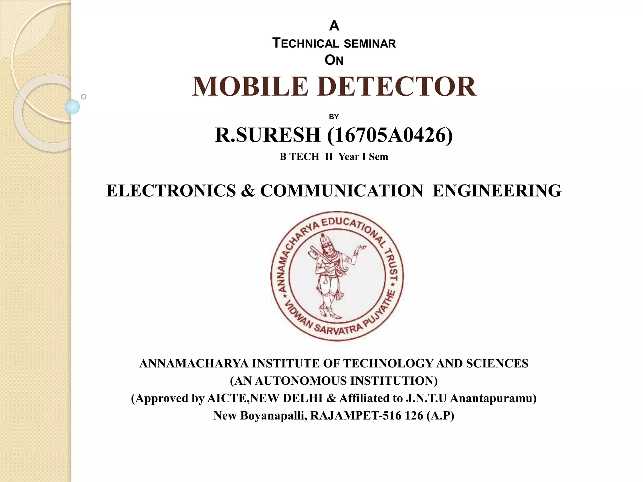


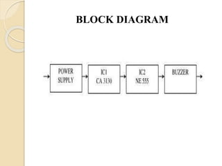

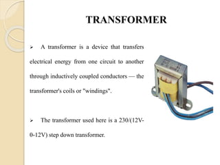
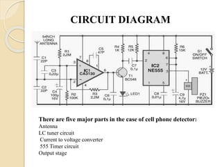


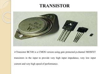


This document describes the design and components of a mobile detector circuit. It includes a block diagram showing the main components: a power supply, transformer, bridge rectifier, op-amp voltage converter, 555 timer circuit, transistor, and piezo buzzer. The detector works by using an antenna to pick up radio frequency signals from an activated mobile phone, which triggers the 555 timer circuit to activate the buzzer, alerting others to the phone's use. The detector has applications in places where mobile phone use needs to be restricted like exam halls, hospitals, and government facilities.


![Space mouse[1]](https://cdn.slidesharecdn.com/ss_thumbnails/spacemouse1-170302013457-thumbnail.jpg?width=640&height=640&fit=bounds)

![5 pen technology[1]](https://cdn.slidesharecdn.com/ss_thumbnails/5pentechnology1-170302013213-thumbnail.jpg?width=640&height=640&fit=bounds)


