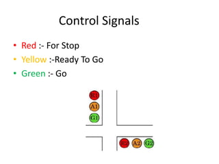
Traffic Light Controller
Submitted to Submitted By
Prof. Rohit Rastogi Nimmi Verma
Preeti
C.S.E(Third Sem)
Acknowledgement
This presentation is prepared on TRAFFIC LIGHT
CONTROL SYSTEM and acknowledges the
dedicated work of Nimmi Verma and Preeti of
B.tech 2nd year (CSE).
Also, a lot of thanks to our Proffs. Mr. Rohit Rastogi
and Mr. Shyam Singh under whose guidance this
presentation have come to success.
We look forward for complementing various critics
who have given comments for the improvisation
of this project.
Content
• Introduction
• Apparatus
• Pin Description
• Circuit Diagram & Working
• Truth Table
• Future Scopes
• Limitations
• Conclusion
Introduction
This two way traffic light project described below is
a small model of traffic light which we see in
Our day to day life on streets.
Basic Idea:- Basic Idea behind this project is to
avoid different collision of vehicles and avoid
the accident.
Control Signals
• Red :- For Stop
• Yellow :-Ready To Go
• Green :- Go
Apparatus
• Bread Board
• Connecting Wire
• Battery
• IC’s
:- CD4017(16 pin CMOS decade counter/ Divider)
:- 4072 ( a dual 4 input OR gate.)
:- 7432 (a quad 2 input OR gate.)
• LED
Pin Description
CD4017:- CD4017 is a16 pin CMOS decade counter/ Divider.
It take clock signal from the clock input and turn on the 10
output in sequence, each time when it receives clock input
pulses.
4072:- 4072 is a dual 4 input OR gate. Output of OR gate goes
high when any of the input goes high and if all input is low
then output is also low.
7432 :- 7432 is a quad 2 input OR gate. In this also output goes
high when any of the input is high and goes low when all
inputs are low.
Working
• First of all make the connections as shown in
circuit diagram.
• When switch is pressed first time output pin 3 of
IC1 goes high . Because of this pin 2 of IC2
become high and Green LED6 will glow. Similarly
this high is also provided to pin 1 of IC3 therefore
its output also goes high indicated by glowing of
RED LED1.
• Similar phenomenon happens when you press
the switch second, third and fourth time. Because
it is making the pin 1 and pin 3 of IC2 and IC3 to
go high
• Now when you press the switch for fifth time pin 10 of
IC1 goes high and this will make all input (2, 3, 4 & 5) of
IC2 low because of that Green LED 6 stop glowing. And
Yellow LED5 connected to Diode D1 start glowing. And
pin 3 of IC3 is high and Red LED1 continuous to glow.
• Now when you press the switch for sixth time pin 1 of
IC1 goes high. Which will make the pin 13 of IC2 goes
high this will glow the Green LED 3. It will also makes
the pin 4 of IC3 high and because of this, pin 6 of IC3
also high and Red LED 4 also glow.
• Now when you press the switch for tenth time pin 11
of IC1 goes high and this will make all input (9, 10, 11 &
12) of IC2 low because of that Green LED 6 stop
glowing. And Yellow LED2 connected to Diode D2 start
glowing. And pin 6 of IC3 is high and Red LED4
continuous to glow.
D1 D2 IC2a IC2b IC3a IC3b R 1 Y 1 G 1 R 2 Y 2 G 3
0 0 1 0 1 0 1 0 0 0 0 1
0 0 1 0 1 0 1 0 0 0 0 1
0 0 1 0 1 0 1 0 0 0 0 1
0 0 1 0 1 0 1 0 0 0 0 1
1 0 0 0 1 0 1 0 0 0 1 0
0 0 0 1 0 1 0 0 1 1 0 0
0 0 0 1 0 1 0 0 1 1 0 0
0 0 0 1 0 1 0 0 1 1 0 0
0 0 0 1 0 1 0 0 1 1 0 0
0 1 0 0 0 1 0 1 0 1 0 0
Future Scope
• Using timer and micro-controller, this circuit
can become more efficient and automatic.
• Using methodology of this circuit we can
design four way traffic light controller also.
Limitations
• This circuit control only two way traffic due to
this reason it is use only in towns and slow
traffic areas.
• This circuit does not contain any type of timer
or micro-controller, so it operates manually.
• This circuit cannot be used in metro city or
where there is more traffic.
Conclusion
Through this knowledgeable presentation we
want to conclude that the traffic light
controller system is the basic need for today’s
busy people.
This system is basically designed through logic
gates and we can further design a four way
controller system.
In a nutshell, this system defines a more
precautive way of preventing day to day
accidents.
Team Member
Nimmi Verma
( niknimnik@gmail.com).
Preeti
(madnawatpreeti6@gmail.com).

Traffic light controller

  • 1.
    Traffic Light Controller Submittedto Submitted By Prof. Rohit Rastogi Nimmi Verma Preeti C.S.E(Third Sem)
  • 2.
    Acknowledgement This presentation isprepared on TRAFFIC LIGHT CONTROL SYSTEM and acknowledges the dedicated work of Nimmi Verma and Preeti of B.tech 2nd year (CSE). Also, a lot of thanks to our Proffs. Mr. Rohit Rastogi and Mr. Shyam Singh under whose guidance this presentation have come to success. We look forward for complementing various critics who have given comments for the improvisation of this project.
  • 3.
    Content • Introduction • Apparatus •Pin Description • Circuit Diagram & Working • Truth Table • Future Scopes • Limitations • Conclusion
  • 4.
    Introduction This two waytraffic light project described below is a small model of traffic light which we see in Our day to day life on streets. Basic Idea:- Basic Idea behind this project is to avoid different collision of vehicles and avoid the accident.
  • 5.
    Control Signals • Red:- For Stop • Yellow :-Ready To Go • Green :- Go
  • 6.
    Apparatus • Bread Board •Connecting Wire • Battery • IC’s :- CD4017(16 pin CMOS decade counter/ Divider) :- 4072 ( a dual 4 input OR gate.) :- 7432 (a quad 2 input OR gate.) • LED
  • 7.
    Pin Description CD4017:- CD4017is a16 pin CMOS decade counter/ Divider. It take clock signal from the clock input and turn on the 10 output in sequence, each time when it receives clock input pulses. 4072:- 4072 is a dual 4 input OR gate. Output of OR gate goes high when any of the input goes high and if all input is low then output is also low. 7432 :- 7432 is a quad 2 input OR gate. In this also output goes high when any of the input is high and goes low when all inputs are low.
  • 9.
    Working • First ofall make the connections as shown in circuit diagram. • When switch is pressed first time output pin 3 of IC1 goes high . Because of this pin 2 of IC2 become high and Green LED6 will glow. Similarly this high is also provided to pin 1 of IC3 therefore its output also goes high indicated by glowing of RED LED1. • Similar phenomenon happens when you press the switch second, third and fourth time. Because it is making the pin 1 and pin 3 of IC2 and IC3 to go high
  • 10.
    • Now whenyou press the switch for fifth time pin 10 of IC1 goes high and this will make all input (2, 3, 4 & 5) of IC2 low because of that Green LED 6 stop glowing. And Yellow LED5 connected to Diode D1 start glowing. And pin 3 of IC3 is high and Red LED1 continuous to glow. • Now when you press the switch for sixth time pin 1 of IC1 goes high. Which will make the pin 13 of IC2 goes high this will glow the Green LED 3. It will also makes the pin 4 of IC3 high and because of this, pin 6 of IC3 also high and Red LED 4 also glow. • Now when you press the switch for tenth time pin 11 of IC1 goes high and this will make all input (9, 10, 11 & 12) of IC2 low because of that Green LED 6 stop glowing. And Yellow LED2 connected to Diode D2 start glowing. And pin 6 of IC3 is high and Red LED4 continuous to glow.
  • 12.
    D1 D2 IC2aIC2b IC3a IC3b R 1 Y 1 G 1 R 2 Y 2 G 3 0 0 1 0 1 0 1 0 0 0 0 1 0 0 1 0 1 0 1 0 0 0 0 1 0 0 1 0 1 0 1 0 0 0 0 1 0 0 1 0 1 0 1 0 0 0 0 1 1 0 0 0 1 0 1 0 0 0 1 0 0 0 0 1 0 1 0 0 1 1 0 0 0 0 0 1 0 1 0 0 1 1 0 0 0 0 0 1 0 1 0 0 1 1 0 0 0 0 0 1 0 1 0 0 1 1 0 0 0 1 0 0 0 1 0 1 0 1 0 0
  • 13.
    Future Scope • Usingtimer and micro-controller, this circuit can become more efficient and automatic. • Using methodology of this circuit we can design four way traffic light controller also.
  • 14.
    Limitations • This circuitcontrol only two way traffic due to this reason it is use only in towns and slow traffic areas. • This circuit does not contain any type of timer or micro-controller, so it operates manually. • This circuit cannot be used in metro city or where there is more traffic.
  • 15.
    Conclusion Through this knowledgeablepresentation we want to conclude that the traffic light controller system is the basic need for today’s busy people. This system is basically designed through logic gates and we can further design a four way controller system. In a nutshell, this system defines a more precautive way of preventing day to day accidents.
  • 17.
    Team Member Nimmi Verma (niknimnik@gmail.com). Preeti (madnawatpreeti6@gmail.com).