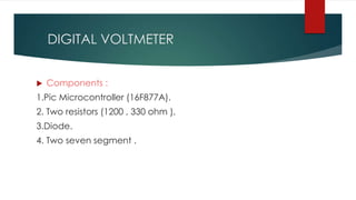
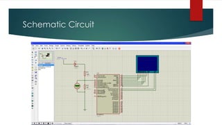
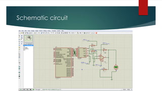
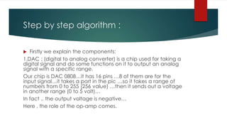
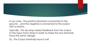
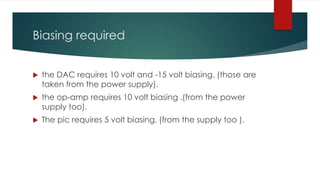
‫الرحيم‬ ‫الرحمن‬ ‫هللا‬ ‫بسم‬
OUR PROJECT IS 2 DEVICES :
1.DIGITAL VOLTMETER.
2.CONTROL VOLTAGE POWER SUPPLY.
DIGITAL VOLTMETER
 Components :
1.Pic Microcontroller (16F877A).
2. Two resistors (1200 , 330 ohm ).
3.Diode.
4. Two seven segment .
Purpose :
Measuring positive voltages.
Schematic Circuit
Schematic of this process.
 In our case … the vertical axis has values from 0 to 5 (volts) … and
ADC samples the signal from 0 to 1023 ( 1024 value) …
approximately , one sample is 0.0049 ... (5/1024) …. And every
value of voltage has an equivalent value of sampling…
 So , the pic reads the value of sampling and multiply it with 0.0049
to get the real value of voltage.
 We used mikroC IDE …it has many built in functions …
 one of them : ADC_READ() … we used this function to do these
steps…
 After we could determine the value of voltage , we display it on
the 2 seven segment .
 The 2 common anode seven segment are connected on the same
lines..
 We used an algorithm to display the 2 numbers on the 2 sev seg.
 The algorithm briefly : turn on the first and turn off the second…. and
send the data of the first one..
 Then turn off the first and turn on the second and send the data of the
second…and so on …
 This operation is performed very fast …(high frequency) …
 So we see the 2 seven segment are on and the number is displayed..
 Finally: we put a diode in the input voltage to
protect our pic from the negative voltage .
 For sure we take in consideration the voltage
drop on the diode ..
CONTROL VOLTAGE POWER SUPPLY.
 COMPONENTS:
1.FIXED 15/-15 VOLT POWER SUPPLY COMPONENTS.
2.pic16F877A.
3.DAC 0808.
4.op-amp 741.
5.Push buttons.
Purpose:
Control the voltage by push buttons …
The output range is from 0 to 10 volts.
Brief Algorithm :
The 2 push buttons increase and decrease the
voltage by giving a signal to the pic…and the pic
send out a signal to the DAC…and the DAC send
a signal to the op-amp … and the op-amp give
us the wanted voltage.
Schematic circuit
Step by step algorithm :
 Firstly we explain the components:
1.DAC : (digital to analog converter) is a chip used for taking a
digital signal and do some functions on it to output an analog
signal with a specific range.
Our chip is DAC 0808…it has 16 pins …8 of them are for the
input signal…it takes a port in the pic …so it takes a range of
numbers from 0 to 255 (256 value) …then it sends out a voltage
in another range (0 to 5 volt)…
In fact .. the output voltage is negative…
Here , the role of the op-amp comes.
2.The op-amp: (operational amplifier ) is a chip used for
many purposes…
Explicitly we deal with the op-amp as a black box …we
don’t know yet the internal construction of this IC.
In our case ..we used it for 2 purposes…
For inverting and amplifying….
Briefly , the op-amp has 2 input terminals (positive and
negative) and an output terminal…
In our case : the positive terminal is connected to the
ground …and the negative is connected to the output
with a resistor…
Typically , the op-amp makes feedback from the output
to the input many times in order to make the two terminals
have the same voltage.
So , the 2 input terminals have 0 volt.
 In addition to the op-amp input terminals have a very
high impedance …so that no current enters it and no
voltage is wasted..
Biasing required
 the DAC requires 10 volt and -15 volt biasing. (those are
taken from the power supply).
 the op-amp requires 10 volt biasing .(from the power
supply too).
 The pic requires 5 volt biasing. (from the supply too ).
 For more information about :
1.Microcontroller : ask ahmad.
2.About pcb and software : ask sabry.
3.About electronic components : ask
sherbiny.
our 1st project
our 1st project

our 1st project

  • 1.
    ‫الرحيم‬ ‫الرحمن‬ ‫هللا‬‫بسم‬ OUR PROJECT IS 2 DEVICES : 1.DIGITAL VOLTMETER. 2.CONTROL VOLTAGE POWER SUPPLY.
  • 2.
    DIGITAL VOLTMETER  Components: 1.Pic Microcontroller (16F877A). 2. Two resistors (1200 , 330 ohm ). 3.Diode. 4. Two seven segment .
  • 3.
  • 4.
  • 5.
  • 6.
     In ourcase … the vertical axis has values from 0 to 5 (volts) … and ADC samples the signal from 0 to 1023 ( 1024 value) … approximately , one sample is 0.0049 ... (5/1024) …. And every value of voltage has an equivalent value of sampling…  So , the pic reads the value of sampling and multiply it with 0.0049 to get the real value of voltage.  We used mikroC IDE …it has many built in functions …  one of them : ADC_READ() … we used this function to do these steps…  After we could determine the value of voltage , we display it on the 2 seven segment .
  • 7.
     The 2common anode seven segment are connected on the same lines..  We used an algorithm to display the 2 numbers on the 2 sev seg.  The algorithm briefly : turn on the first and turn off the second…. and send the data of the first one..  Then turn off the first and turn on the second and send the data of the second…and so on …  This operation is performed very fast …(high frequency) …  So we see the 2 seven segment are on and the number is displayed..
  • 8.
     Finally: weput a diode in the input voltage to protect our pic from the negative voltage .  For sure we take in consideration the voltage drop on the diode ..
  • 9.
    CONTROL VOLTAGE POWERSUPPLY.  COMPONENTS: 1.FIXED 15/-15 VOLT POWER SUPPLY COMPONENTS. 2.pic16F877A. 3.DAC 0808. 4.op-amp 741. 5.Push buttons.
  • 10.
    Purpose: Control the voltageby push buttons … The output range is from 0 to 10 volts.
  • 11.
    Brief Algorithm : The2 push buttons increase and decrease the voltage by giving a signal to the pic…and the pic send out a signal to the DAC…and the DAC send a signal to the op-amp … and the op-amp give us the wanted voltage.
  • 12.
  • 13.
    Step by stepalgorithm :  Firstly we explain the components: 1.DAC : (digital to analog converter) is a chip used for taking a digital signal and do some functions on it to output an analog signal with a specific range. Our chip is DAC 0808…it has 16 pins …8 of them are for the input signal…it takes a port in the pic …so it takes a range of numbers from 0 to 255 (256 value) …then it sends out a voltage in another range (0 to 5 volt)… In fact .. the output voltage is negative… Here , the role of the op-amp comes.
  • 14.
    2.The op-amp: (operationalamplifier ) is a chip used for many purposes… Explicitly we deal with the op-amp as a black box …we don’t know yet the internal construction of this IC. In our case ..we used it for 2 purposes… For inverting and amplifying…. Briefly , the op-amp has 2 input terminals (positive and negative) and an output terminal…
  • 15.
    In our case: the positive terminal is connected to the ground …and the negative is connected to the output with a resistor… Typically , the op-amp makes feedback from the output to the input many times in order to make the two terminals have the same voltage. So , the 2 input terminals have 0 volt.
  • 16.
     In additionto the op-amp input terminals have a very high impedance …so that no current enters it and no voltage is wasted..
  • 17.
    Biasing required  theDAC requires 10 volt and -15 volt biasing. (those are taken from the power supply).  the op-amp requires 10 volt biasing .(from the power supply too).  The pic requires 5 volt biasing. (from the supply too ).
  • 18.
     For moreinformation about : 1.Microcontroller : ask ahmad. 2.About pcb and software : ask sabry. 3.About electronic components : ask sherbiny.