1. Digital electronics deals with data and codes represented in a digital format using two conditions: 0 and 1.
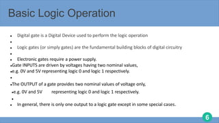
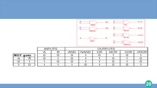
2. Digital circuits are made from logic gates, which perform operations on binary inputs to produce binary outputs according to truth tables.
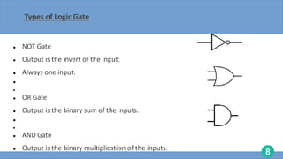
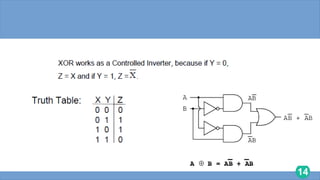
3. Common logic gates include AND, OR, NOT, NAND, NOR, XOR, and XNOR gates, which can be combined to perform more complex operations.


![[Deck] What's New in Spark-Iceberg Integration via DSV2.pptx](https://cdn.slidesharecdn.com/ss_thumbnails/deckwhatsnewinspark-icebergintegrationviadsv2-260210005337-25955b12-thumbnail.jpg?width=640&height=640&fit=bounds)


