This document compares two current controllers - hysteresis control and proportional-integral (PI) control - for a five-level cascaded H-bridge multilevel inverter. Hysteresis control provides excellent dynamic performance but variable switching frequency, while PI control with sinusoidal pulse width modulation provides fixed switching frequency and better harmonic performance. Simulation results show that PI control achieves lower total harmonic distortion than hysteresis control under different load conditions, though hysteresis control has faster response. PI control is thus better suited for applications requiring lower harmonic distortion.
![International Journal Of Computational Engineering Research (ijceronline.com) Vol. 2 Issue. 6
Comparison of Current Controllers for a Five-level Cascaded H-Bridge
Multilevel Inverter
Sundararajan K1, Alamelu Nachiappan2, Veerapathiran G3
1
Sathyabama University, Chennai,
2, 3
Pondicherry Engineering College, Puducherry, India,
Abstract:
The hysteresis current controller provides excellent dynamic performance, whereas the Proportional-Integral
controller provides instantaneous current control and wave shaping, fixed inverter switching frequency resulting in only known
harmonics. A comparative study between Hysteresis current control and Proportional-Integral (PI) current control using
sinusoidal pulse width modulation (SPWM) techniques for a five-level cascaded H-bridge multilevel inverter is presented in
this paper. A comparison has been made in terms of total harmonic distortion (THD) level at the three phase load current. The
simulation study has been carried out with the help of MATLAB Simulink software and the performance of such controllers has
been observed during load variations.
Keywords: Cascaded H-Bridge, Current controller, Hysteresis controller, Multilevel inverter, PI controller, Sinusoidal pulse
width modulation (SPWM), Total harmonic distortion (THD)
1. Introduction
Presently, large electric drives and utility applications require advanced power electronics converters to meet the high
power demands. As a result, multilevel inverter technology is a very efficient alternative for medium-voltage and high-power
applications because of its fruitful advantages [1-4]. It can realize high voltage and high power output by using semiconductor
switches without the use of transformer and dynamic voltage balance circuits. When the number of output levels increases, the
harmonic content in the output voltage and current as well as electromagnetic interference decreases. The basic concept of a
multilevel inverter is to achieve high power by using a series of power semiconductor switches with several lower dc voltage
sources to perform the power conversion by synthesizing a staircase voltage waveform [4]. To obtain a low distortion output
voltage nearly sinusoidal, a triggering signal should be generated to control the switching frequency of each power
semiconductor switch. In the proposed study the triggering signals to multi level inverter (MLI) are designed by using the
Sinusoidal Pulse Width Modulation (SPWM) technique.
The well-established topologies of multilevel inverters include neutral point clamped (NPC), flying capacitor and
Cascaded H-bridge (CHB). These inverters have several advantages over the traditional inverters. The CHB inverter
configuration has recently become very popular in high-power AC supplies and adjustable-speed drive applications. The CHB
multilevel inverter is designed with a series of H-bridge (single-phase full bridge) inverter units in each of its three phases. The
main focus of this paper is on the CHB inverter with different current control techniques including PI current control and
hysteresis current control. These current control techniques are studied and compared with each other for analyzing their
advantages and disadvantages. The current control techniques are also analyzed and compared based on current tracking,
output quality, Total Harmonic distortion (THD), Modulation index and Load variations. To show the performance of the
proposed CHB inverter, the MATLAB-simulink is used to simulate the five-level CHB inverter with the proposed current
control techniques. The design and simulation of the five-level CHB inverter with predictive current control has to be
introduced as a future work of this paper.
2. Inverter Model
The cascaded H-bridge multilevel inverter model is based on the series connection of H-bridges with separate dc
sources. Since the output terminals of the H-bridges are connected in series, the dc sources must be isolated from each other
(Fig.1). Owing to this property, CHB-MLIs have also been proposed to be used with fuel cells or photovoltaic arrays in order
to achieve higher levels [1,5-7]. The resulting ac output voltage is synthesized by the addition of the voltages generated by
different H-bridge cells. Each single phase H-bridge generates three voltage levels as +Vdc, 0, -Vdc by connecting the dc
source to the ac output by different combinations of four switches (S11 , S12 ,S13 and S14).
Issn 2250-3005(online) October| 2012 Page 55](https://image.slidesharecdn.com/j026055062-121102023656-phpapp02/75/J026055062-1-2048.jpg)
![International Journal Of Computational Engineering Research (ijceronline.com) Vol. 2 Issue. 6
(7)
The load model can be expressed also as a vector equation using the following vectorial transformation:
(8)
where a, b, and c are the three-phase variables of voltage or current, and α and β are the vectorial variables. Using this
transformation, (5) can be described in terms of the vectorial variables α−β as
(9)
where vα,β is the inverter voltage vector and iα,β is the load current vector.
3. Modulation Techniques For CHB Inverter
There are different modulation techniques available for a CHB multilevel inverter [8-10]. Among all those techniques,
PWM technique which produces less total harmonic distortion (THD) values is most preferable. Phase Shifted PWM (PS-
PWM) and Level-shifted PWM (LS-PWM) are the natural extension of traditional PWM techniques. For generating triggering
pulses to MLI, pure sinusoidal wave as modulating signal and multi carrier signal which is of triangular in shape have been
considered [11]. For an L-level CHB inverter, (L-1) carrier signals are required.
In PSPWM, a phase shift is introduced between the carrier signals of contiguous cells, producing a phase-shifted
switching pattern between them. When connected together, a stepped multilevel waveform is originated. It has been
demonstrated that the lowest distortion can be achieved when the phase shifts between carriers are 180°/C (where C is the
number of power cells) (Fig.2). The phase-shifts of the carriers produce multiplicative effect, which means that the total output
voltage has a switching pattern with C times the frequency of the switching pattern of each cell. Hence, better total harmonic
distortion (THD) is obtained at the output, using C times lower frequency carriers.
Figure 2. Phase Shifted PWM (PS-PWM)
In Level-shifted PWM (LS-PWM), the L-1 carriers are arranged in vertical shifts instead of the phase-shift used in PS-
PWM. The carriers span the whole amplitude range that can be generated by the inverter.
They can be arranged in vertical shifts, with all the signals in phase with each other, called phase disposition (PD-PWM);
with all the positive carriers in phase with each other and in opposite phase of the negative carriers, known as phase opposition
disposition (POD-PWM); and alternate phase opposition disposition (APOD-PWM), which is obtained by alternating the phase
between adjacent carriers [12]. An example of the phase disposition (PD-PWM) for the five-level CHB inverter (thus four
carriers) is given in Fig. 3.
Figure 3. Phase disposition (PD-PWM)
Issn 2250-3005(online) October| 2012 Page 57](https://image.slidesharecdn.com/j026055062-121102023656-phpapp02/75/J026055062-3-2048.jpg)
![International Journal Of Computational Engineering Research (ijceronline.com) Vol. 2 Issue. 6
4. Analysis of Current Controllers
4.1. Hysteresis current controller
The hysteresis modulation for power electronic converters is attractive in many different applications because of its
unmatched dynamic response and wide command-tracking bandwidth. The hysteresis modulation is a feedback current control
method where the load current tracks the reference current within a hysteresis band in nonlinear load application of CHB
multilevel inverter. The block diagram of a hysteresis control of an H-bridge is shown in Fig.4a and the operation principle of
the hysteresis modulation in Fig.4b. The controller generates the sinusoidal reference current of desired magnitude and
frequency that is compared with the actual line current. If the current exceeds the upper limit of the hysteresis band, the next
higher voltage level should be selected to attempt to force the current error towards zero. However, the new inverter voltage
level may not be sufficient to return the current error to zero and inverter should switch to next higher voltage level until the
correct voltage level is selected. As a result, the current gets back into the hysteresis band, and the actual current is forced to
track the reference current within the hysteresis band. Three hysteresis controllers which are used to implement the correct
voltage level selection are defined as double offset band three level, double band three level, and time-based three level
hysteresis controllers [13, 14].
The switching frequency changes according to variations of the load parameters and operating conditions. This is one
of the major drawbacks [15] of hysteresis control, since variable switching frequency can cause resonance problems. In
addition, the switching losses restrict the application of hysteresis control to lower power levels.
(b)
Figure 4. Hysteresis current control: (a) block diagram of an H-bridge cell with hysteresis controller, (b) hysteresis
current band and voltage curves of load feedback
4.2. Proportional-Integral Current Controller Using PWM
The PI current controller with PWM control scheme is shown in Fig.5. The error between the reference and the
measured load current is processed by the PI controller to generate the reference voltages. A modulator is needed to generate
the drive signals for the inverter switches. The reference load voltages are compared with a triangular carrier signal, and the
output of each comparator is used to drive the CHB multilevel inverter.
Issn 2250-3005(online) October| 2012 Page 58](https://image.slidesharecdn.com/j026055062-121102023656-phpapp02/75/J026055062-4-2048.jpg)


![International Journal Of Computational Engineering Research (ijceronline.com) Vol. 2 Issue. 6
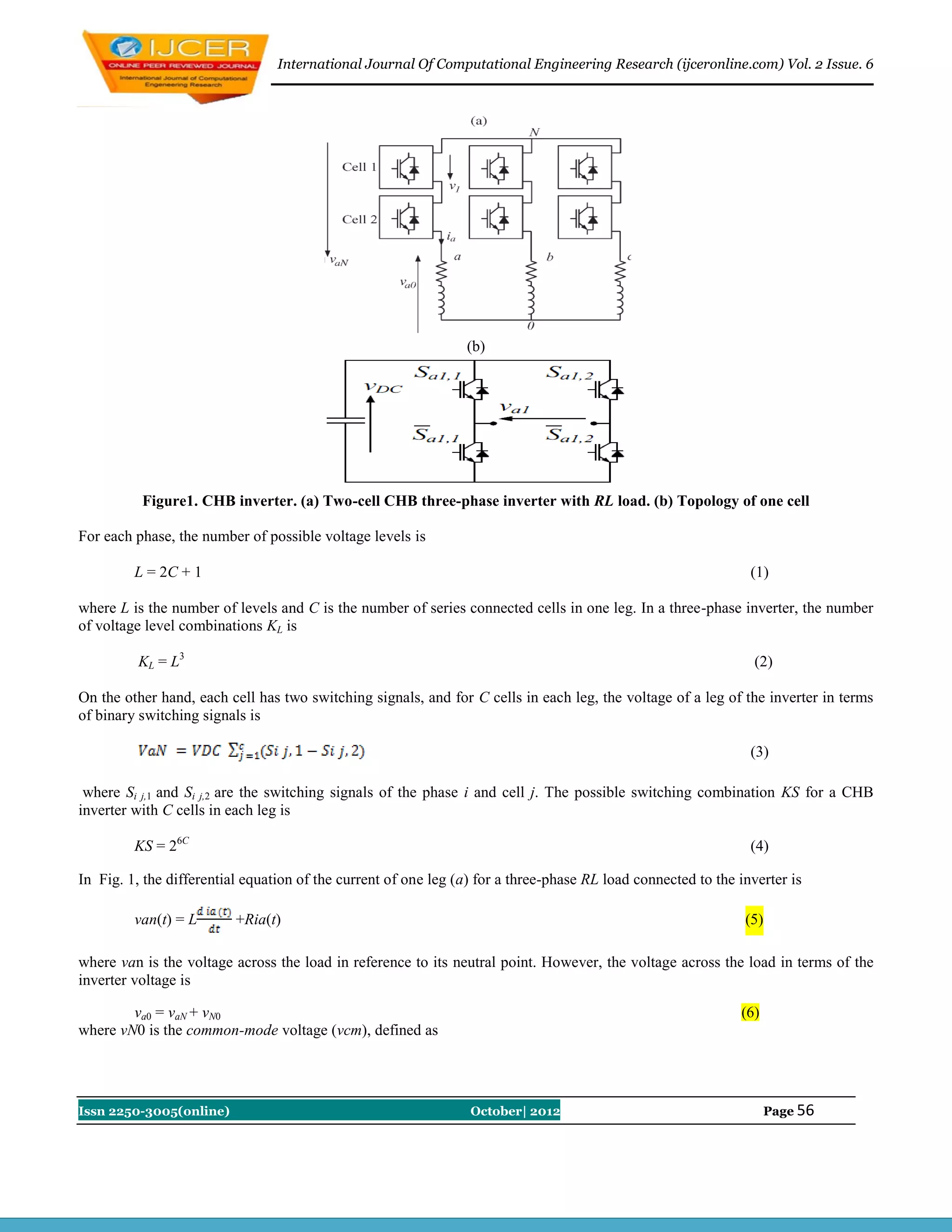
Table 2. Comparison of parameters for hysteresis and PI current controller
Different Loads PI Current Controller Hysteresis Current Controller
R=96Ω ,L=35mH THD=3.38% THD=6.96%
R=96Ω ,L=30mH THD=3.95% THD=6.90%
R=47Ω ,L=15mH THD=8.51% THD=10.76%
R=47Ω ,L=10mH THD=10.15% THD=12.14%
The different load parameters were tested and observed for the comparison of the performance of the hysteresis
control and PI control with PWM techniques. The comparison results are shown in the table 2. As the load value increases, the
THD value also increases but the PI current controller shows better response compared to the Hysteresis Controller. From fig.8
(a-d), it can be observed that the hysteresis control produces continuous and wide frequency range output current spectrum,
which is considered as a disadvantage of this method. From fig. 9 (a-d), it is observed that the harmonic content generated
when using the PI current control, is concentrated around the carrier frequency. This is considered as an advantage of the PI
current control over the hysteresis control.
6. Conclusion
The CHB multilevel inverter's current has been controlled by the Hysteresis and Proportional - Integral (PI) current
controllers. Hysteresis controller shows good dynamic response but with some noticeable disturbances in voltage and current
waveforms. The PI current controller with PWM modulation technique shows slower response due to the dynamics of the
closed current loops, but performed better compared to the hysteresis current controller. The harmonic spectrums for the two
control methods were compared and the simulation results show that the current spectrum obtained with PI current control is
better than the hysteresis current controller.
References
[1] J.Rodriguez, J.-S. Lai, and F. Z. Peng, “Multilevel inverters: A survey of topologies, controls, and applications,” IEEE Trans. Ind.
Electron., vol. 49, no. 4, , pp. 724–738 Aug. 2002.
[2]. Holmes, D.G, McGrath, B.P., “Multicarrier PWM strategies for multilevel inverters”, IEEE Trans. Ind. Electron., Vol. 49, issue:4,
pp.858-867, Aug 2002
[3]. Yan Deng, Hongyan Wang, Chao Zhang, Lei Hu and Xiangning He, “Multilevel PWM Methods Based On Control Degrees Of
Freedom Combination And Its Theoretical Analysis”, IEEE IAS 2005 Conference record no.:0-7803-9208-6/05, pp.1692 – 1699,
2005.
[4]. J. Rodriguez, B. Wu, S. Bernet, J. Pontt, and S. Kouro, “Multilevel voltage source-converter topologies for industrial medium-voltage
drives”, IEEE Trans. Ind. Electron., vol. 54, no. 6, pp. 2930–2945, Dec. 2007.
[5] Panagis P, Stergiopoulos F, Marabeas P, Manias S. Comparison of state of the art multilevel inverters. In: Proceedings of IEEE
annual power electronics specialist conference PESC „08, Rhodes (Greece), 2008.
[6] Hochgraf C, Lasseter R, Divan D, Lipo TA. “Comparison of multilevel inverters for static VAR compensation”, In: Proceedings of
IEEE ind appl society annual meeting, 1994.
[7] Kuhn H, Ruger NE, Mertens A., “ Control strategy for multilevel inverter with non-ideal dc sources”, In Proceedings of IEEE power
electronics specialists conf. Orlando (USA), 2007.
[8] S. Bernet, Tutorial, “Multi Level converters”, in Proc. Power Electron. Spec. Conf. (PESC 04), Aachen, Germany, Jun 20, 2004.
[9] B.Wu, “High Power converters and AC motor drives”, in Proc. Power Electron. Spec. Conf. (PESC 05), Recife, Brazil, Jun. 2005.
[10] J. Rodrı´guez, S. Kouro, and P. Lezana, B, “Tutorial on multilevel converters”, in Proc. Power Electron. Intell.
Contr. Energy Conserv. (PELINCEC 2005), Warsaw, Poland, Oct. 2005.
[11] J. Rodrı´guez, Ed., B, “ Special section on multilevel inverters”, Part I, IEEE Trans. Ind. Electron., vol. 49, Aug. 2002.
[12] G. Carrara, S. Gardella, M. Marchesoni, R. Salutari, and G. Sciutto, B, “A new multilevel PWM method: A theoretical analysis”,
IEEE Trans. Power Electron., vol. 7, Jul. 1992, pp. 497–505.
[13] Bojovi RI, Griva G, Bostan V, Guerreiro M, Farina F, Profumo F., “Current control strategy for power conditioners using sinusoidal
signal integrators in synchronous reference frame”, IEEE Trans Power Electron, 2005; 20:pp.1402–12.
[14] Kang BJ, Liaw CM., “Random hysteresis PWM inverter with robust spectrum shaping”, IEEE Trans Aerospace Electron Syst
2001;37:619–28.
[15] Carl N.M.,Victor S.P. Cheung, and Henry S.H. Chung, “Constant Frequency Hysteresis Current Control of Grid-Connected VSI
without Bandwidth Control”, Energy Conversion Congress and Exposition, 2009. ECCE 2009.
Issn 2250-3005(online) October| 2012 Page 62](https://image.slidesharecdn.com/j026055062-121102023656-phpapp02/75/J026055062-8-2048.jpg)


![[IJET-V2I3P17] Authors: R.C.Rohini, G.Srividhya](https://cdn.slidesharecdn.com/ss_thumbnails/ijet-v2i3p17-160711110843-thumbnail.jpg?width=640&height=640&fit=bounds)