Download as PDF, PPTX


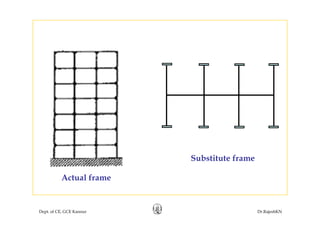
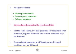
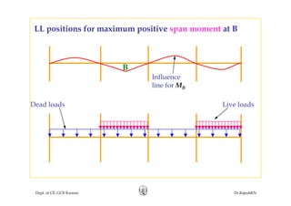
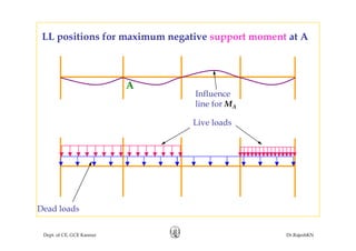
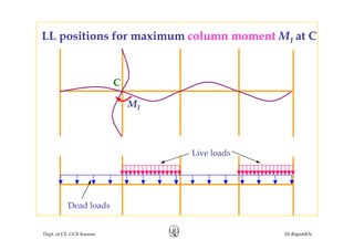
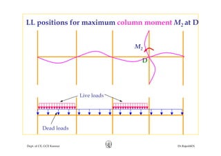
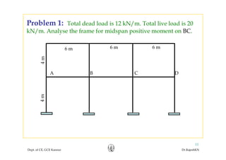
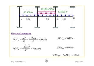
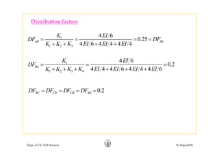
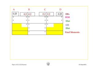
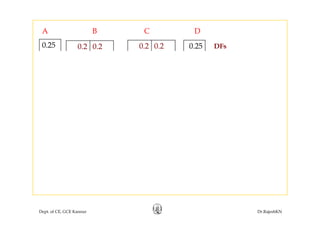
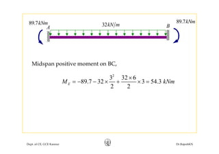
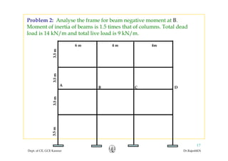
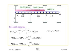
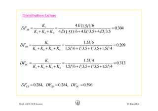
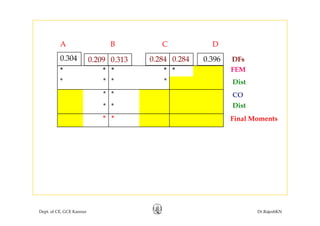
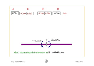
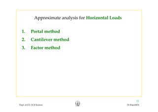
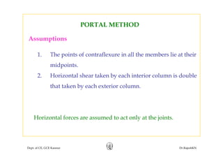
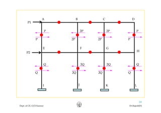
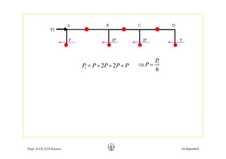
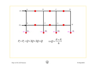
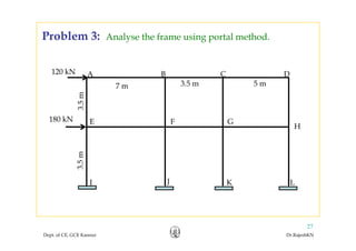
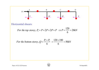
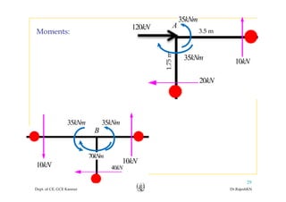
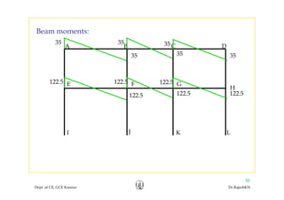
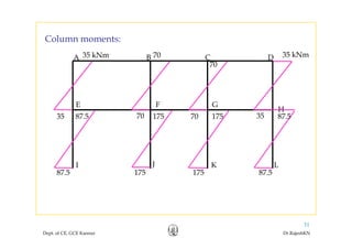
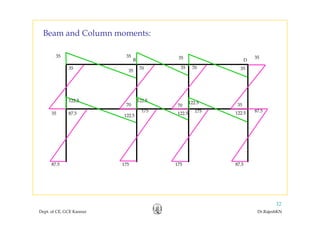
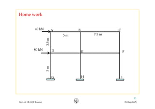
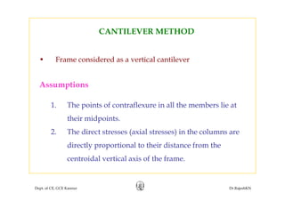
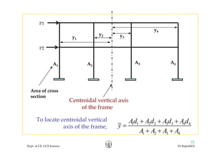
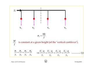
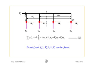
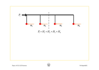
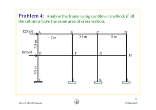
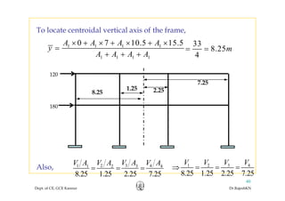
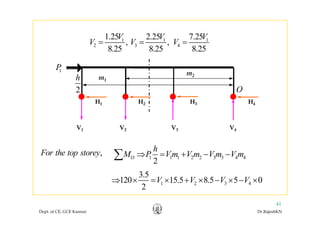
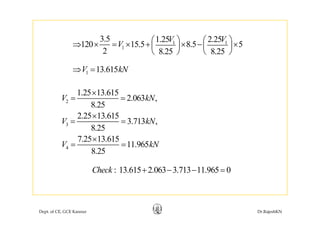
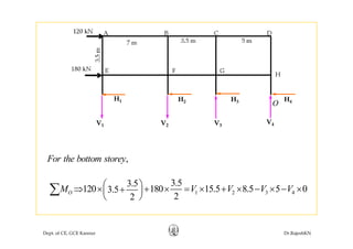
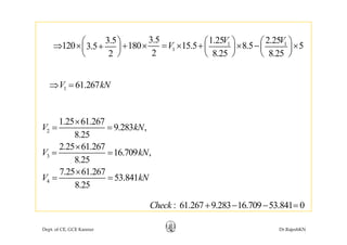
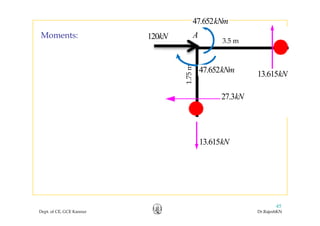
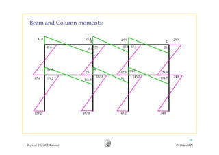
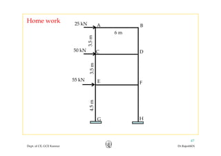
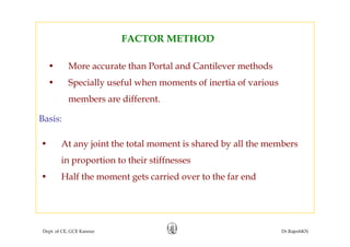
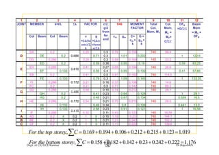
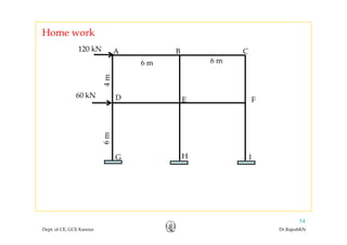
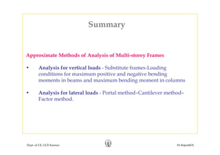

This document discusses approximate analysis methods for multi-storey frames under vertical and lateral loads. It introduces the substitute frame method, portal method, and cantilever method for analyzing frames. An example problem demonstrates using the substitute frame method to analyze a frame for vertical loads, distributing fixed end moments using distribution factors. Homework is assigned to analyze another frame using the cantilever method under given loading conditions.