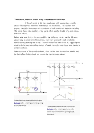
This document describes the development of an automatic fan system that controls fan speed based on room temperature. It uses a LM35 temperature sensor to detect temperature changes and an LM3914 integrated circuit to automatically adjust the fan speed through relays. The system aims to enable automatic fan speed control, develop an automatic fan system that changes speed according to temperature, and allow users to view the temperature and speed status on an LCD display. It works by sensing temperature with the LM35 sensor and sending the output to the LM3914 IC, which activates relays to change the fan speed as the temperature rises or falls.

![9.2 Importance
The transistor is the key active component in practically all
modern electronics. Many consider it to be one of the greatest inventions of the 20th
century. Its importance in today's society rests on its ability to be mass-produced using
a highly automated process (semiconductor device fabrication) that achieves
astonishingly low per-transistor costs. The invention of the first transistor at Bell
Labs was named an IEEE Milestone in 2009.
Although several companies each produce over a billion individually packaged (known
as discrete) transistors every year, the vast majority of transistors are now produced
in integrated circuits (often shortened to IC, microchips or simply chips), along
with diodes, resistors, capacitors and other electronic components, to produce
complete electronic circuits. A logic gate consists of up to about twenty transistors
whereas an advanced microprocessor, as of 2009, can use as many as 3 billion
transistors (MOSFETs). "About 60 million transistors were built in 2002 ... for [each]
man, woman, and child on Earth."
The transistor's low cost, flexibility, and reliability have made it a ubiquito us device.
Transistorized mechatronic circuits have replaced electromechanical devices in
controlling appliances and machinery. It is often easier and cheaper to use a
standard microcontroller and write a computer program to carry out a control function
than to design an equivalent mechanical control function.](https://image.slidesharecdn.com/projectreport-141124140422-conversion-gate02/85/temperature-dependent-dc-fan-speed-controller-withou-using-micrcontroller-32-320.jpg)

![within the magnetic core. Perfect coupling implies infinitely high core magnetic
permeability and winding inductances and zero net magnetomotive force.
A varying current in the transformer's primary winding creates a varying magnetic flux
in the core and a varying magnetic field impinging on the secondary winding. This
varying magnetic field at the secondary induces a varying electromotive force (emf) or
voltage in the secondary winding. The primary and secondary windings are wrapped
around a core of infinitely high magnetic permeability[e] so that all of the magnetic flux
passes through both the primary and secondary windings. With a voltage source
connected to the primary winding and load impedance connected to the secondary
winding, the transformer currents flow in the indicated directions.
According to Faraday's law of induction, since the same magnetic flux passes through
both the primary and secondary windings in an ideal transformer,[7] a voltage is induced
in each winding, according to eq. (1) in the secondary winding case, according to eq. (2)
in the primary winding case. The primary emf is sometimes termed counter emf. This
is in accordance with Lenz's law, which states that induction of emf always opposes
development of any such change in magnetic field.
Ideal transformer equations (eq.)
By Faraday's law of induction
. . . (1)[a]
. . . (2)
Combining ratio of (1) & (2)
Turns ratio . . . (3) where
for step-down transformers, a > 1
for step-up transformers, a < 1
By law of Conservation of Energy, apparent,real and reactive power are each
conserved in the input and output
. . . (4)
Combining (3) & (4) with this endnote yields the ideal transformer identity](https://image.slidesharecdn.com/projectreport-141124140422-conversion-gate02/85/temperature-dependent-dc-fan-speed-controller-withou-using-micrcontroller-41-320.jpg)
![. (5)
By Ohm's Law and ideal transformer identity
. . . (6)
Apparent load impedance Z'L (ZL referred to the primary)
. (7)
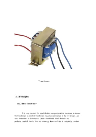
11.2.2 Real transformer
The ideal transformer model assumes that all flux generated by the primary
winding links all the turns of every winding, including itself. In practice, some flux
traverses paths that take it outside the windings. Such flux is termed leakage flux, and
results in leakage inductance in series with the mutually coupled transformer windings.
Leakage flux results in energy being alternately stored in and discharged from the
magnetic fields with each cycle of the power supply. It is not directly a power loss, but
results in inferior voltage regulation, causing the secondary voltage not to be directly
proportional to the primary voltage, particularly under heavy load. Transformers are
therefore normally designed to have very low leakage inductance.
In some applications increased leakage is desired, and long magnetic paths, air gaps, or
magnetic bypass shunts may deliberately be introduced in a transformer design to limit
the short-circuit current it will supply. Leaky transformers may be used to supply loads
that exhibit negative resistance, such as electric arcs, mercury vapor lamps, and neon
signs or for safely handling loads that become periodically short-circuited such
as electric arc welders.
Air gaps are also used to keep a transformer from saturating, especially
audio-frequency transformers in circuits that have a DC component flowing in the
windings.
Knowledge of leakage inductance is also useful when transformers are operated in
parallel. It can be shown that if the percent impedance[l] and associated winding leakage
reactance-to-resistance (X/R) ratio of two transformers were hypothetically exactly the](https://image.slidesharecdn.com/projectreport-141124140422-conversion-gate02/85/temperature-dependent-dc-fan-speed-controller-withou-using-micrcontroller-42-320.jpg)