Downloaded 2,355 times

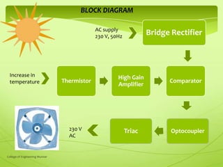
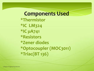
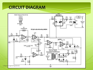
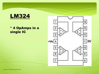


The document presents a mini project on an automatic temperature-controlled fan developed by students from the College of Engineering, Munnar. It details the components used, including thermistors and triacs, and explains their functions within the circuit designed to regulate fan speed based on temperature changes. The project is currently in progress, with the circuit successfully implemented at the breadboard level.


![Tamperature controlled fan_project_report[1]](https://cdn.slidesharecdn.com/ss_thumbnails/tamperaturecontrolledfanprojectreport1-170912121052-thumbnail.jpg?width=640&height=640&fit=bounds)


