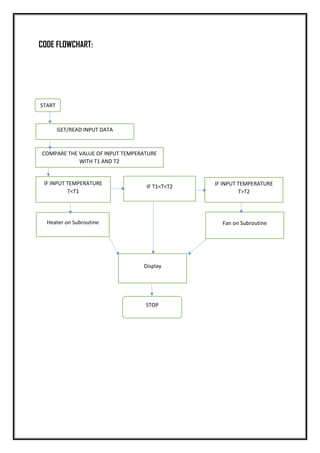
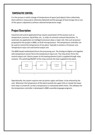
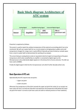
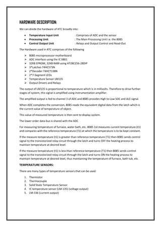
AUTOMATIC TEMPERATURE CONTROL AND READOUT
Project By:
Jayant Vig (70/EC/13) and Lavaneesh Sharma (87/EC/13) of Electronics and
Communication Engineering Department, of Netaji Subhas Institute of
Technology, Section-II.
Synopsis:
The aim of the project is to display current temperature and control/maintain
the temperature of a plant/home within a desired limit.
Course name:
EC-316 Microprocessor Lab Project.
Introduction:
In our project we are trying to achieve an optimal environment for home/plant working
conditions so that the temperature we wish to work in is always achieved and maintained
irrespective of changes in the external environment.
The system is implemented using the Intel 8085A, an 8-bit microprocessor introduced in
1976. Eagle software was used to draw out its schematic and board files. It is implemented
on a Printed Circuit Board (PCB).
Motivation and Justification:
The motivation for this project came to us while we were sitting and sipping coffee on a
chilly winter night in Delhi. We hoped fo a de i e hi h ould se se the ha ges in
temperature inside the room and eradicate the need for us to keep changing the intensity of
heater when it got too hot or too cold.
TEMPERAUTRE CONTROL:
It is the process in which change of temperature of space (and objects there collectively
there within) is measured or otherwise detected and the passage of heat energy into or out
of the space is adjusted to achieve a desired temperature range.
Project Description:
Industrial and control application/may require automation of the process such as
temperature, pressure, liquid flow, etc., in order to minimize manual intervention. To
automate any application an intelligent processor plays a major role. One such processor
proposed for the project is 8085, an 8-bit microprocessor. The temperature controller can
be used to control the temperature of any plant. Typically it contains a Processor unit,
Temperature input unit and Control output unit.
The 8085 based motherboard forms the processing unit. The Analog-to-Digital unit together
with temperature sensor forms the temperature input unit. The relay driver forms the
control output unit. Electric power to the heating element (coil) is supplied through relay
contacts. The switching ON/OFF of the relay controls the heat supplied to the plant.
Operationally, the system requires two set points-upper and lower, to be entered by the
user. Whenever the temperature of the plant exceeds the upper limit or recede the lower
limit relay is turned-off, so that a temperature is maintained within limits. The software for
the temperature controller is developed in 8085 assembly language programs.
Flowchart is explained as follows:
The sensor is used to report the ambient temperature of the external surrounding which has to be
monitored. We will use a water bath for our current project as bringing about sudden and small
temperature changes for a large room is quite difficult. Basically we have limited our sample space
from a room to water bath to demonstrate the working of our project.
The sensor being an analog device sends an equivalent electrical signal corresponding to the given
temperature which when amplified by an amplifier is converted to digital signal as the
Microprocessor only understands digital signals ie in the binary form of zeros and ones. The ADC we
have used is AD0801.
Finally the digital signal is fed into the microprocessor unit which further decodes what to do.
Basic Operation of ATC unit:
Operationally the ATC requires two set points:
: - Upper set point
: - Lower set point
Whenever the temperature of the plant exceeds the upper set point the cooler (in our project we
have used a DC fan) is turned into operation and whenever the temperature falls below the lower
set point the heater is turned on (we have used a dc bulb to indicate presence of heat radiation).
SCHEMATIC:
HARDWARE DESCRIPTION:
We can divide the hardware of ATC broadly into:
 Temperature Input Unit : Comprises of ADC and the sensor
 Processing Unit : The Main Processing Unit i.e. the 8085
 Control Output Unit : Relays and Output Control and Read-Out
The Hardware used in ATC comprises of the following
 8085 microprocessor motherboard
 ADC interface using the IC 0801
 32KB EPROM, 32KB RAM using AT28C256-28DIP
 3*Latches 74HC573N
 2*Decoder 74HCT138N
 2*7-Segment LEDs
 Temperature Sensor LM135
 Output Drivers and Relays
The output of LM135 is proportional to temperature which is in millivolts. Therefore to drive further
stages of system, this signal is amplified using instrumentation amplifier.
The amplified output is fed to channel 3 of ADC and 8085 provides High to Low SOC and ALE signal.
When ADC completes the conversion, 8085 reads the equivalent digital data from the latch which is
the current value of temperature of object.
This value of measured temperature is then sent to display system.
The lower order data-bus is shared with the ADC
For measuring temperature of furnace, water bath, etc. 8085 1st measures current temperature (t1)
and compares with the reference temperature (T1) at which the temperature is to be kept constant.
If the measure temperature (t1) is greater than reference temperature (T1) then 8085 sends control
signal to the transistorized relay circuit through the latch and turns OFF the heating process to
maintain temperature at desired level.
If the measure temperature (t1) is less than reference temperature (T1) then 8085 sends control
signal to the transistorized relay circuit through the latch and turns ON the heating process to
maintain temperature at desired level, thus maintaining the temperature of furnace, bath tub, etc.
TEMPERATURE SENSORS:
There are many types of temperature sensors that can be used:
1. Thermistor
2. Thermocouple
3. Solid State Temperature Sensor
4. IC temperature sensor (LM-135) (voltage output)
5. LM-336 (current output)
8085: The Microprocessor
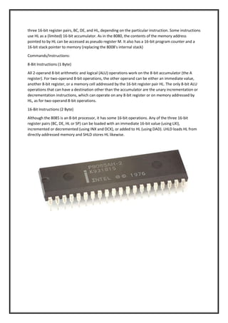
The 8085 is a conventional von Neumann design based on the Intel 8080. Unlike the 8080 it does not
multiplex state signals onto the data bus, but the 8-bit data bus is instead multiplexed with the lower
8-bits of the 16-bit address bus to limit the number of pins to 40. State signals are provided by
dedicated bus control signal pins and two dedicated bus state ID pins named S0 and S1. Pin 40 is
used for the power supply (+5 V) and pin 20 for ground. Pin 39 is used as the Hold pin. Pins 15 to 8
are generally used for address buses.[clarification needed] The processor was designed using nMOS
circuitry, and the later "H" versions were implemented in Intel's enhanced nMOS process called
HMOS ("High-performance MOS"), originally developed for fast static RAM products. Only a single 5
volt power supply is needed, like competing processors and unlike the 8080. The 8085 uses
approximately 6,500 transistors
The 8085 has extensions to support new interrupts, with three mask able vectored interrupts (RST
7.5, RST 6.5 and RST 5.5), one non-mask able interrupt (TRAP), and one externally serviced interrupt
(INTR). Each of these five interrupts has a separate pin on the processor, a feature which permits
simple systems to avoid the cost of a separate interrupt controller.
The processor has seven 8-bit registers accessible to the programmer, named A, B, C, D, E, H, and L,
where A is the 8-bit accumulator and the other six can be used as independent byte-registers or as
three 16-bit register pairs, BC, DE, and HL, depending on the particular instruction. Some instructions
use HL as a (limited) 16-bit accumulator. As in the 8080, the contents of the memory address
pointed to by HL can be accessed as pseudo register M. It also has a 16-bit program counter and a
16-bit stack pointer to memory (replacing the 8008's internal stack)
Commands/Instructions:
8-Bit Instructions (1 Byte)
All 2-operand 8-bit arithmetic and logical (ALU) operations work on the 8-bit accumulator (the A
register). For two-operand 8-bit operations, the other operand can be either an immediate value,
another 8-bit register, or a memory cell addressed by the 16-bit register pair HL. The only 8-bit ALU
operations that can have a destination other than the accumulator are the unary incrementation or
decrementation instructions, which can operate on any 8-bit register or on memory addressed by
HL, as for two-operand 8-bit operations.
16-Bit Instructions (2 Byte)
Although the 8085 is an 8-bit processor, it has some 16-bit operations. Any of the three 16-bit
register pairs (BC, DE, HL or SP) can be loaded with an immediate 16-bit value (using LXI),
incremented or decremented (using INX and DCX), or added to HL (using DAD). LHLD loads HL from
directly-addressed memory and SHLD stores HL likewise.
LM-135:
The LM135 series are precision, easily-calibrated, integrated circuit temperature sensors. Operating
as a 2-terminal zener, the LM135 has a breakdown voltage directly proportional to absolute
temperature at 10 mV/°K. With less than 1-Ω dy a i i peda e, the de i e ope ates o er a
current range of 400 µA to 5 mA with virtually no change in performance. When calibrated at 25°C,
the LM135 has typically less than 1°C error over a 100°C temperature range. Unlike other sensors,
the LM135 has a linear output.
Applications for the LM135 include almost any type of temperature sensing over a –55°C to 150°C
temperature range. The low impedance and linear output make interfacing to readout or control
circuitry are especially easy.
The LM135 operates over a –55°C to 150°C temperature range while the LM235 operates over a –
40°C to 125°C temperature range. The LM335 operates from –40°C to 100°C. The LMx35 devices are
available packaged in hermetic TO transistor packages while the LM335 is also available in plastic.
Features
 Directly Calibrated to the Kelvin Temperature
Scale
 1°C Initial Accuracy Available
 Operates from 400 µA to 5 mA
 Less than 1-Ω Dy a i I peda e
 Easily Calibrated
 Wide Operating Temperature Range
 200°C Overrange
 Low Cost
Analog to Digital Convertor: ADC0801
An analog-to-digital converter (ADC, A/D, A–D, or A-to-D) is a device that converts a continuous
physical quantity (usually voltage) to a digital number that represents the quantity's amplitude.
The conversion involves quantization of the input, so it necessarily introduces a small amount of
error. Furthermore, instead of continuously performing the conversion, an ADC does the conversion
periodically, sampling the input. The result is a sequence of digital values that have been converted
from a continuous-time and continuous-amplitude analog signal to a discrete-time and discrete-
amplitude digital signal.
The ADC0801 series are versatile 8-Bit µP compatible general purpose ADC converters operate on
single 5-V supply. These devices are treated as a memory location or I/O port to a micro-processor
system without additional interface logic. The outputs are Tri-state latched which facilitate
interfacing to micro-processor control bus. The converter is designed with a differential
potentiometric ladder, a circuit equivalent of the 256R network. It contains analog switches
sequenced by successive approximation logic. All of the package pin outs are shown and the major
logic control paths are drawn in heavier weight lines. The differential analog voltage input has good
common mode-rejection and permits offsetting the analog zero-input voltage value. Moreover, the
input reference voltage can be adjusted to allow encoding small analog voltage span to the full 8-bits
resolution. To ensure start-up under all possible conditions, an external WR pulse is required during
the first power-up cycle.
BOARD FILE:
The Board file obtained after the schematic was completed and the routing process was done.
COMPARISON OF INTERIM PROJECT REPORTS:
Expected IPR:
Observed IPR:
CONCLUSION:
INPUT DEVICES:
USER INPUT Push Button, Toggle Switch, SPST/SPDT/MPMT selector
switches, Switch Matrix, Capacitive touch, Resistive touch,
Reed switch (with a magnet input
Sound Microphone, Ultrasonic
Magnetic Field Hall Effect, Inductor, Reed switch, Magnetometer
Distance Ultrasonic ranger, IR proximity sensor
Temperature Thermistor, RTD, Thermocouple, Semiconductor
Sensor
Light LDR, Photodiode, LED as sensor
Strain/Force Strain gauge, FSR, Piezo
Relative Position Shaft encoder (Stepper Motor as a shaft encoder),
Gyroscope, Opt coupler, Linear potentiometer,
GPS
Image Camera (CMOS or CCD), Linear CCD array
Time RTC, Clock + Counter
CONTROLLER
COMMUNICATION &
NETWORK
O/P DEVIES
HOST
I/P DEVICES
POWER
SUPPLY
OUTPUT DEVICES:
Light LED, RGB LED, Laser, IR
Visual Seven/Alphanumeric Display, Character LCD,
Graphics LCD, TV
Sound Speaker, Buzzer, Ultrasound, Melody Generator
Temperature Heater, Peltier
Position Stepper Motor (Micro stepping mode), DC
Motor, Servo Motor, Servo mechanism,
Solenoid
POWER SUPPLY:
Linear or Switching, Switching Topologies Buck, boost or buck-boost Energy sources Battery
technologies
CONTROLLER:
MSP430: Low Power Mixed Signal Controller MSP432: Low Power ARM Cortex M Controller C2000:
Low Power Digital Signal Controller Tiva ARM: ARM Cortex M4F Controller
COMMUNICATION NETWORK:
Inter-device and/or Intra-device UART, SPI, I2C LIN, CAN Ethernet, WiFi USB
The interconnection of these sections was fully understood and using the embedded systems the
project was implemented. Hands-o p oje ts app oa h is fou d to e e efi ial i lea i g the
concepts related to embedded system design. By restricting the hands-on project to conform a
framework enforces an element of uniformity in the activity, which can be managed with limited
human resource. Allowing the participants to explore and implement the actual design by their own
efforts provides them with independence and infuses a sense of achievement that has a large
g atifi atio uotie t.
APPLICATIONS OF THE PROJECT & FUTURE SCOPE OF PROJECT:
 This is a very basic implementation and design of home automation system
 Few changes will be needed in order to implement the system with microcontroller
 It should be able to control various ranges of temperature
 If we use microcontroller then the cost will be minimum
If we had to choose any other device other than microprocessor we could have implemented it with
an 8 bit Magnitude comparator.
BIBLIOGAPHY:
 We want to thank our Professor D.V. Gadre Sir for his incredible support and constant
motivation and guidance whenever we needed it the most. Sir also taught us the patience
required for a long period of time in implementing such projects, and also introduced us to
the microprocessor based systems.
 Microprocessors Architecture Programming and Applications with 8085 – by R.S. Ganokar,
Fifth Edition (Penram International Publishing)
 Introduction to Microprocessor- by A.P. Mathur (Tata McGraw-Hill publishing)
 https://www.scribd.com/doc/68632956/Temperature-Controller-Using-8085-
Microprocessor#scribd
 http://www.ti.com/product/LM135
 https://en.wikipedia.org/wiki/Intel_8085
 http://www.daenotes.com/electronics/digital-electronics/Intel-8085-8-bit-microprocessor
 https://drive.google.com/file/d/0B1nfn420l7PycjIyeWZMcUxNTHc/view?usp=sharing
WHILE WORKING:
CODE FLOWCHART:
START
GET/READ THE DATA FROM THE INPUT
COMPARE THE VALUE OF CURRENT TEMPERATURE
START
GET/READ INPUT DATA
COMPARE THE VALUE OF INPUT TEMPERATURE
WITH T1 AND T2
IF INPUT TEMPERATURE
T<T1
IF T1<T<T2 IF INPUT TEMPERATURE
T>T2
Heater on Subroutine Fan on Subroutine
Display
STOP
FLOWCHART EXPLAINATION:
 The process starts by first reading the data from the input port, the value of the temperature
is converted into 8 data bits by the ADC.
 The data bus is shared and the data received is sent to the MPU where in the value of data is
compared with set magnitudes of temperatures T1 and T2. T represents the current value of
the temperature received.
 The next step is the comparison process wherein the magnitude of temperature (input) is
compared using the CPI instruction twice.
 First it is compared with the lower temperature, however we can compare any value of
te pe atu e fi st. He e e ha e hose the lo e li it fi st the efo e it’s o pa ed ith
hex value of 10°C. If the temperature is found to be lesser than 10 then the subroutine for
heater (in our case a light bulb) is serviced which in turn turns on the heater.
 Secondly it is then checked if the input temperature is greater than the upper temperature
li it of 35°C. If it’s highe tha that the the su outi e fo the oole i ou ase a d fa
is serviced.
 If the temperature is midway in between these two ranges then the value of the
temperature is just displayed. The value of current temperature is displayed all together in
any case.
 The operation is sent to halt when the full cycle is completed.

Microprocessor project

  • 1.
    AUTOMATIC TEMPERATURE CONTROLAND READOUT Project By: Jayant Vig (70/EC/13) and Lavaneesh Sharma (87/EC/13) of Electronics and Communication Engineering Department, of Netaji Subhas Institute of Technology, Section-II. Synopsis: The aim of the project is to display current temperature and control/maintain the temperature of a plant/home within a desired limit. Course name: EC-316 Microprocessor Lab Project.
  • 2.
    Introduction: In our projectwe are trying to achieve an optimal environment for home/plant working conditions so that the temperature we wish to work in is always achieved and maintained irrespective of changes in the external environment. The system is implemented using the Intel 8085A, an 8-bit microprocessor introduced in 1976. Eagle software was used to draw out its schematic and board files. It is implemented on a Printed Circuit Board (PCB). Motivation and Justification: The motivation for this project came to us while we were sitting and sipping coffee on a chilly winter night in Delhi. We hoped fo a de i e hi h ould se se the ha ges in temperature inside the room and eradicate the need for us to keep changing the intensity of heater when it got too hot or too cold.
  • 3.
    TEMPERAUTRE CONTROL: It isthe process in which change of temperature of space (and objects there collectively there within) is measured or otherwise detected and the passage of heat energy into or out of the space is adjusted to achieve a desired temperature range. Project Description: Industrial and control application/may require automation of the process such as temperature, pressure, liquid flow, etc., in order to minimize manual intervention. To automate any application an intelligent processor plays a major role. One such processor proposed for the project is 8085, an 8-bit microprocessor. The temperature controller can be used to control the temperature of any plant. Typically it contains a Processor unit, Temperature input unit and Control output unit. The 8085 based motherboard forms the processing unit. The Analog-to-Digital unit together with temperature sensor forms the temperature input unit. The relay driver forms the control output unit. Electric power to the heating element (coil) is supplied through relay contacts. The switching ON/OFF of the relay controls the heat supplied to the plant. Operationally, the system requires two set points-upper and lower, to be entered by the user. Whenever the temperature of the plant exceeds the upper limit or recede the lower limit relay is turned-off, so that a temperature is maintained within limits. The software for the temperature controller is developed in 8085 assembly language programs.
  • 4.
    Flowchart is explainedas follows: The sensor is used to report the ambient temperature of the external surrounding which has to be monitored. We will use a water bath for our current project as bringing about sudden and small temperature changes for a large room is quite difficult. Basically we have limited our sample space from a room to water bath to demonstrate the working of our project. The sensor being an analog device sends an equivalent electrical signal corresponding to the given temperature which when amplified by an amplifier is converted to digital signal as the Microprocessor only understands digital signals ie in the binary form of zeros and ones. The ADC we have used is AD0801. Finally the digital signal is fed into the microprocessor unit which further decodes what to do. Basic Operation of ATC unit: Operationally the ATC requires two set points: : - Upper set point : - Lower set point Whenever the temperature of the plant exceeds the upper set point the cooler (in our project we have used a DC fan) is turned into operation and whenever the temperature falls below the lower set point the heater is turned on (we have used a dc bulb to indicate presence of heat radiation).
  • 5.
  • 6.
    HARDWARE DESCRIPTION: We candivide the hardware of ATC broadly into:  Temperature Input Unit : Comprises of ADC and the sensor  Processing Unit : The Main Processing Unit i.e. the 8085  Control Output Unit : Relays and Output Control and Read-Out The Hardware used in ATC comprises of the following  8085 microprocessor motherboard  ADC interface using the IC 0801  32KB EPROM, 32KB RAM using AT28C256-28DIP  3*Latches 74HC573N  2*Decoder 74HCT138N  2*7-Segment LEDs  Temperature Sensor LM135  Output Drivers and Relays The output of LM135 is proportional to temperature which is in millivolts. Therefore to drive further stages of system, this signal is amplified using instrumentation amplifier. The amplified output is fed to channel 3 of ADC and 8085 provides High to Low SOC and ALE signal. When ADC completes the conversion, 8085 reads the equivalent digital data from the latch which is the current value of temperature of object. This value of measured temperature is then sent to display system. The lower order data-bus is shared with the ADC For measuring temperature of furnace, water bath, etc. 8085 1st measures current temperature (t1) and compares with the reference temperature (T1) at which the temperature is to be kept constant. If the measure temperature (t1) is greater than reference temperature (T1) then 8085 sends control signal to the transistorized relay circuit through the latch and turns OFF the heating process to maintain temperature at desired level. If the measure temperature (t1) is less than reference temperature (T1) then 8085 sends control signal to the transistorized relay circuit through the latch and turns ON the heating process to maintain temperature at desired level, thus maintaining the temperature of furnace, bath tub, etc. TEMPERATURE SENSORS: There are many types of temperature sensors that can be used: 1. Thermistor 2. Thermocouple 3. Solid State Temperature Sensor 4. IC temperature sensor (LM-135) (voltage output) 5. LM-336 (current output)
  • 7.
    8085: The Microprocessor The8085 is a conventional von Neumann design based on the Intel 8080. Unlike the 8080 it does not multiplex state signals onto the data bus, but the 8-bit data bus is instead multiplexed with the lower 8-bits of the 16-bit address bus to limit the number of pins to 40. State signals are provided by dedicated bus control signal pins and two dedicated bus state ID pins named S0 and S1. Pin 40 is used for the power supply (+5 V) and pin 20 for ground. Pin 39 is used as the Hold pin. Pins 15 to 8 are generally used for address buses.[clarification needed] The processor was designed using nMOS circuitry, and the later "H" versions were implemented in Intel's enhanced nMOS process called HMOS ("High-performance MOS"), originally developed for fast static RAM products. Only a single 5 volt power supply is needed, like competing processors and unlike the 8080. The 8085 uses approximately 6,500 transistors The 8085 has extensions to support new interrupts, with three mask able vectored interrupts (RST 7.5, RST 6.5 and RST 5.5), one non-mask able interrupt (TRAP), and one externally serviced interrupt (INTR). Each of these five interrupts has a separate pin on the processor, a feature which permits simple systems to avoid the cost of a separate interrupt controller. The processor has seven 8-bit registers accessible to the programmer, named A, B, C, D, E, H, and L, where A is the 8-bit accumulator and the other six can be used as independent byte-registers or as
  • 8.
    three 16-bit registerpairs, BC, DE, and HL, depending on the particular instruction. Some instructions use HL as a (limited) 16-bit accumulator. As in the 8080, the contents of the memory address pointed to by HL can be accessed as pseudo register M. It also has a 16-bit program counter and a 16-bit stack pointer to memory (replacing the 8008's internal stack) Commands/Instructions: 8-Bit Instructions (1 Byte) All 2-operand 8-bit arithmetic and logical (ALU) operations work on the 8-bit accumulator (the A register). For two-operand 8-bit operations, the other operand can be either an immediate value, another 8-bit register, or a memory cell addressed by the 16-bit register pair HL. The only 8-bit ALU operations that can have a destination other than the accumulator are the unary incrementation or decrementation instructions, which can operate on any 8-bit register or on memory addressed by HL, as for two-operand 8-bit operations. 16-Bit Instructions (2 Byte) Although the 8085 is an 8-bit processor, it has some 16-bit operations. Any of the three 16-bit register pairs (BC, DE, HL or SP) can be loaded with an immediate 16-bit value (using LXI), incremented or decremented (using INX and DCX), or added to HL (using DAD). LHLD loads HL from directly-addressed memory and SHLD stores HL likewise.
  • 9.
    LM-135: The LM135 seriesare precision, easily-calibrated, integrated circuit temperature sensors. Operating as a 2-terminal zener, the LM135 has a breakdown voltage directly proportional to absolute temperature at 10 mV/°K. With less than 1-Ω dy a i i peda e, the de i e ope ates o er a current range of 400 µA to 5 mA with virtually no change in performance. When calibrated at 25°C, the LM135 has typically less than 1°C error over a 100°C temperature range. Unlike other sensors, the LM135 has a linear output. Applications for the LM135 include almost any type of temperature sensing over a –55°C to 150°C temperature range. The low impedance and linear output make interfacing to readout or control circuitry are especially easy. The LM135 operates over a –55°C to 150°C temperature range while the LM235 operates over a – 40°C to 125°C temperature range. The LM335 operates from –40°C to 100°C. The LMx35 devices are available packaged in hermetic TO transistor packages while the LM335 is also available in plastic. Features  Directly Calibrated to the Kelvin Temperature Scale  1°C Initial Accuracy Available  Operates from 400 µA to 5 mA  Less than 1-Ω Dy a i I peda e  Easily Calibrated  Wide Operating Temperature Range  200°C Overrange  Low Cost
  • 10.
    Analog to DigitalConvertor: ADC0801 An analog-to-digital converter (ADC, A/D, A–D, or A-to-D) is a device that converts a continuous physical quantity (usually voltage) to a digital number that represents the quantity's amplitude. The conversion involves quantization of the input, so it necessarily introduces a small amount of error. Furthermore, instead of continuously performing the conversion, an ADC does the conversion periodically, sampling the input. The result is a sequence of digital values that have been converted from a continuous-time and continuous-amplitude analog signal to a discrete-time and discrete- amplitude digital signal. The ADC0801 series are versatile 8-Bit µP compatible general purpose ADC converters operate on single 5-V supply. These devices are treated as a memory location or I/O port to a micro-processor system without additional interface logic. The outputs are Tri-state latched which facilitate interfacing to micro-processor control bus. The converter is designed with a differential potentiometric ladder, a circuit equivalent of the 256R network. It contains analog switches sequenced by successive approximation logic. All of the package pin outs are shown and the major logic control paths are drawn in heavier weight lines. The differential analog voltage input has good common mode-rejection and permits offsetting the analog zero-input voltage value. Moreover, the input reference voltage can be adjusted to allow encoding small analog voltage span to the full 8-bits resolution. To ensure start-up under all possible conditions, an external WR pulse is required during the first power-up cycle.
  • 11.
    BOARD FILE: The Boardfile obtained after the schematic was completed and the routing process was done.
  • 12.
    COMPARISON OF INTERIMPROJECT REPORTS: Expected IPR: Observed IPR:
  • 13.
    CONCLUSION: INPUT DEVICES: USER INPUTPush Button, Toggle Switch, SPST/SPDT/MPMT selector switches, Switch Matrix, Capacitive touch, Resistive touch, Reed switch (with a magnet input Sound Microphone, Ultrasonic Magnetic Field Hall Effect, Inductor, Reed switch, Magnetometer Distance Ultrasonic ranger, IR proximity sensor Temperature Thermistor, RTD, Thermocouple, Semiconductor Sensor Light LDR, Photodiode, LED as sensor Strain/Force Strain gauge, FSR, Piezo Relative Position Shaft encoder (Stepper Motor as a shaft encoder), Gyroscope, Opt coupler, Linear potentiometer, GPS Image Camera (CMOS or CCD), Linear CCD array Time RTC, Clock + Counter CONTROLLER COMMUNICATION & NETWORK O/P DEVIES HOST I/P DEVICES POWER SUPPLY
  • 14.
    OUTPUT DEVICES: Light LED,RGB LED, Laser, IR Visual Seven/Alphanumeric Display, Character LCD, Graphics LCD, TV Sound Speaker, Buzzer, Ultrasound, Melody Generator Temperature Heater, Peltier Position Stepper Motor (Micro stepping mode), DC Motor, Servo Motor, Servo mechanism, Solenoid POWER SUPPLY: Linear or Switching, Switching Topologies Buck, boost or buck-boost Energy sources Battery technologies CONTROLLER: MSP430: Low Power Mixed Signal Controller MSP432: Low Power ARM Cortex M Controller C2000: Low Power Digital Signal Controller Tiva ARM: ARM Cortex M4F Controller COMMUNICATION NETWORK: Inter-device and/or Intra-device UART, SPI, I2C LIN, CAN Ethernet, WiFi USB The interconnection of these sections was fully understood and using the embedded systems the project was implemented. Hands-o p oje ts app oa h is fou d to e e efi ial i lea i g the concepts related to embedded system design. By restricting the hands-on project to conform a framework enforces an element of uniformity in the activity, which can be managed with limited human resource. Allowing the participants to explore and implement the actual design by their own efforts provides them with independence and infuses a sense of achievement that has a large g atifi atio uotie t.
  • 15.
    APPLICATIONS OF THEPROJECT & FUTURE SCOPE OF PROJECT:  This is a very basic implementation and design of home automation system  Few changes will be needed in order to implement the system with microcontroller  It should be able to control various ranges of temperature  If we use microcontroller then the cost will be minimum If we had to choose any other device other than microprocessor we could have implemented it with an 8 bit Magnitude comparator.
  • 17.
    BIBLIOGAPHY:  We wantto thank our Professor D.V. Gadre Sir for his incredible support and constant motivation and guidance whenever we needed it the most. Sir also taught us the patience required for a long period of time in implementing such projects, and also introduced us to the microprocessor based systems.  Microprocessors Architecture Programming and Applications with 8085 – by R.S. Ganokar, Fifth Edition (Penram International Publishing)  Introduction to Microprocessor- by A.P. Mathur (Tata McGraw-Hill publishing)  https://www.scribd.com/doc/68632956/Temperature-Controller-Using-8085- Microprocessor#scribd  http://www.ti.com/product/LM135  https://en.wikipedia.org/wiki/Intel_8085  http://www.daenotes.com/electronics/digital-electronics/Intel-8085-8-bit-microprocessor  https://drive.google.com/file/d/0B1nfn420l7PycjIyeWZMcUxNTHc/view?usp=sharing
  • 18.
  • 20.
    CODE FLOWCHART: START GET/READ THEDATA FROM THE INPUT COMPARE THE VALUE OF CURRENT TEMPERATURE START GET/READ INPUT DATA COMPARE THE VALUE OF INPUT TEMPERATURE WITH T1 AND T2 IF INPUT TEMPERATURE T<T1 IF T1<T<T2 IF INPUT TEMPERATURE T>T2 Heater on Subroutine Fan on Subroutine Display STOP
  • 21.
    FLOWCHART EXPLAINATION:  Theprocess starts by first reading the data from the input port, the value of the temperature is converted into 8 data bits by the ADC.  The data bus is shared and the data received is sent to the MPU where in the value of data is compared with set magnitudes of temperatures T1 and T2. T represents the current value of the temperature received.  The next step is the comparison process wherein the magnitude of temperature (input) is compared using the CPI instruction twice.  First it is compared with the lower temperature, however we can compare any value of te pe atu e fi st. He e e ha e hose the lo e li it fi st the efo e it’s o pa ed ith hex value of 10°C. If the temperature is found to be lesser than 10 then the subroutine for heater (in our case a light bulb) is serviced which in turn turns on the heater.  Secondly it is then checked if the input temperature is greater than the upper temperature li it of 35°C. If it’s highe tha that the the su outi e fo the oole i ou ase a d fa is serviced.  If the temperature is midway in between these two ranges then the value of the temperature is just displayed. The value of current temperature is displayed all together in any case.  The operation is sent to halt when the full cycle is completed.