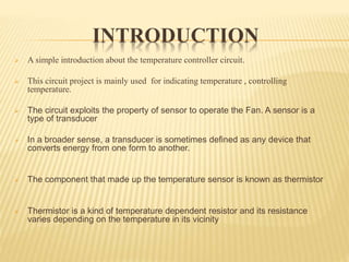
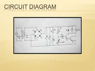
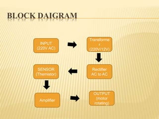
FAN CONTROLLED BY USING TEMPERATURE
SENSOR
BY
B NANDEESH
CONTENTS
 Objective of project
 Introduction
 Components used
 Circuit diagram
 Working
 Advantages
 Disadvantages
OBJECTIVE OF PROJECT
Our object of making this project is for reducing the power consumption. And
also to assist people who are disabled and are unable to control the speed of
fan.
It may also be used for monitoring changes in environment.
In near future, it can also be used in different industries and electronic devices.
INTRODUCTION
 A simple introduction about the temperature controller circuit.
 This circuit project is mainly used for indicating temperature , controlling
temperature.
 The circuit exploits the property of sensor to operate the Fan. A sensor is a
type of transducer
 In a broader sense, a transducer is sometimes defined as any device that
converts energy from one form to another.
 The component that made up the temperature sensor is known as thermistor
 Thermistor is a kind of temperature dependent resistor and its resistance
varies depending on the temperature in its vicinity
There are two types of Thermistors
 Negative Temperature Coefficient Thermistor (NTC)
 Positive Temperature Coefficient Thermistor (PTC).
 NTC Thermistor decreases its resistance when the temperature increases

 PTC Thermistor increases its resistance when the temperature increases.
 A small DC fan increases or decreases its speed as per the temperature change.
When the temperature decreases below a certain level, Fan automatically turns off.
 The main principle of this project to monitoring and to control the temperature.

COMPONENTS USED:-
 Temperature Sensor
 Resistor
 Capacitor
 DC power supply
 LED
 Diodes
 NPN Transistor
 Motor
 transformer
 Electric Fan 12V
 Vero board
 propeller
RESISTOR:-
A resistor is a two-terminal electronic component that produces a voltage
across its terminals that is proportional to the electric current through it in
accordance with Ohm's law:
V = IR
The primary characteristics of a resistor are the resistance, the tolerance,
maximum working voltage and the power rating. Other characteristics
include temperature coefficient, noise, and inductance.
CAPACITOR:-
 The capacitor's function is to store electricity, or electrical energy.
 The capacitor is constructed with two electrode plates facing each other, but
separated by an insulator.
 When DC voltage is applied to the capacitor, an electric charge is stored on
each electrode.
 While the capacitor is charging up, current flows.
 The current will stop flowing when the capacitor has fully charged.
LED:-
 A light-emitting diode (LED) is an electronic light source.
 LEDs are used as indicator lamps in many kinds of electronics and increasingly
for lighting.
 LEDs are based on the semiconductor diode.
 The longer lead is the Anode side and the short one is the Cathode side.
TEMPERATURE SENSOR:-
 The temperature sensor is known as the “Thermistor”
 A thermistor is an electronic component that exhibits a large change in
resistance with a change in its body temperature.
 The word “Thermistor” is actually a contraction of the words “Thermal
Resistor”.
DIODE:-
 A diode is a semiconductor device which allows current to flow through it in
only one direction.
 Although a transistor is also a semiconductor device, it does not operate the way
a diode does.
 A diode is specifically made to allow current to flow through it in only one
direction.
NTC THERMISTOR
 The NTC thermistors are composed of metal
oxides
 The most commonly used oxides are
those of manganese, nickel, cobalt, iron, copper and titanium.
 A mixture of two or more metal oxide powders are combined with
suitable binders, are formed to a desired geometry, dried and sintered at
an elevated temperature
CIRCUIT DIAGRAM
BLOCK DAIGRAM
INPUT
(220V AC)
Transforme
r
(220V/12V)
SENSOR
(Themistor)
Rectifier
AC to AC
OUTPUT
(motor
rotating)
Amplifier
WORKING
 The main intension is to control the fan by heating the sensor, i.e. the thermistor, where
the speed of the fan is dependent and controlled by any device’s temperature like PC. As
the temperature of the device increases or decreases, the speed of fan increases or
decreases respectively. So it can be used mainly as a cooling device. By modifying the
circuit slightly, it can also be used to control the room temperature, depending on the
property of thermistor.
 The thermistor used in the circuit here, decreases its resistance with increasing
temperature, hence the electrical conductivity also increases, increasing voltage across it,
resulting in an increment in the speed of the fan. Thus, it is possible to control the speed
of the fan automatically when the device’s temperature varies. Experiment can be
followed to evaluate whether this circuit can save energy through the use of temperature
sensor and thus promote efficiency.
ADVANTAGES:-
 This project can be used in Home.
 This project can be used in Industry.
 This will help in saving the energy / electricity.
 To monitor the environments that is not comfortable, or possible, for
humans to monitor, especially for extended periods of time.
 Prevents waste of energy when it’s not hot enough for a fan to be
needed.
 To assist people who are disabled to adjust the fan speed
automatically.
DISADVANTAGES:-
 It can only be maintained by technical person. Thus, it becomes difficult to be
maintained.
 Due to temperature variation, after sometimes its efficiency may decrease.
fan speed control by using temperature sensor

fan speed control by using temperature sensor

  • 1.
    FAN CONTROLLED BYUSING TEMPERATURE SENSOR BY B NANDEESH
  • 2.
    CONTENTS  Objective ofproject  Introduction  Components used  Circuit diagram  Working  Advantages  Disadvantages
  • 3.
    OBJECTIVE OF PROJECT Ourobject of making this project is for reducing the power consumption. And also to assist people who are disabled and are unable to control the speed of fan. It may also be used for monitoring changes in environment. In near future, it can also be used in different industries and electronic devices.
  • 4.
    INTRODUCTION  A simpleintroduction about the temperature controller circuit.  This circuit project is mainly used for indicating temperature , controlling temperature.  The circuit exploits the property of sensor to operate the Fan. A sensor is a type of transducer  In a broader sense, a transducer is sometimes defined as any device that converts energy from one form to another.  The component that made up the temperature sensor is known as thermistor  Thermistor is a kind of temperature dependent resistor and its resistance varies depending on the temperature in its vicinity
  • 5.
    There are twotypes of Thermistors  Negative Temperature Coefficient Thermistor (NTC)  Positive Temperature Coefficient Thermistor (PTC).  NTC Thermistor decreases its resistance when the temperature increases   PTC Thermistor increases its resistance when the temperature increases.  A small DC fan increases or decreases its speed as per the temperature change. When the temperature decreases below a certain level, Fan automatically turns off.  The main principle of this project to monitoring and to control the temperature. 
  • 6.
    COMPONENTS USED:-  TemperatureSensor  Resistor  Capacitor  DC power supply  LED  Diodes  NPN Transistor  Motor  transformer  Electric Fan 12V  Vero board  propeller
  • 7.
    RESISTOR:- A resistor isa two-terminal electronic component that produces a voltage across its terminals that is proportional to the electric current through it in accordance with Ohm's law: V = IR The primary characteristics of a resistor are the resistance, the tolerance, maximum working voltage and the power rating. Other characteristics include temperature coefficient, noise, and inductance.
  • 8.
    CAPACITOR:-  The capacitor'sfunction is to store electricity, or electrical energy.  The capacitor is constructed with two electrode plates facing each other, but separated by an insulator.  When DC voltage is applied to the capacitor, an electric charge is stored on each electrode.  While the capacitor is charging up, current flows.  The current will stop flowing when the capacitor has fully charged.
  • 9.
    LED:-  A light-emittingdiode (LED) is an electronic light source.  LEDs are used as indicator lamps in many kinds of electronics and increasingly for lighting.  LEDs are based on the semiconductor diode.  The longer lead is the Anode side and the short one is the Cathode side.
  • 10.
    TEMPERATURE SENSOR:-  Thetemperature sensor is known as the “Thermistor”  A thermistor is an electronic component that exhibits a large change in resistance with a change in its body temperature.  The word “Thermistor” is actually a contraction of the words “Thermal Resistor”.
  • 11.
    DIODE:-  A diodeis a semiconductor device which allows current to flow through it in only one direction.  Although a transistor is also a semiconductor device, it does not operate the way a diode does.  A diode is specifically made to allow current to flow through it in only one direction.
  • 12.
    NTC THERMISTOR  TheNTC thermistors are composed of metal oxides  The most commonly used oxides are those of manganese, nickel, cobalt, iron, copper and titanium.  A mixture of two or more metal oxide powders are combined with suitable binders, are formed to a desired geometry, dried and sintered at an elevated temperature
  • 13.
  • 14.
  • 15.
    WORKING  The mainintension is to control the fan by heating the sensor, i.e. the thermistor, where the speed of the fan is dependent and controlled by any device’s temperature like PC. As the temperature of the device increases or decreases, the speed of fan increases or decreases respectively. So it can be used mainly as a cooling device. By modifying the circuit slightly, it can also be used to control the room temperature, depending on the property of thermistor.  The thermistor used in the circuit here, decreases its resistance with increasing temperature, hence the electrical conductivity also increases, increasing voltage across it, resulting in an increment in the speed of the fan. Thus, it is possible to control the speed of the fan automatically when the device’s temperature varies. Experiment can be followed to evaluate whether this circuit can save energy through the use of temperature sensor and thus promote efficiency.
  • 16.
    ADVANTAGES:-  This projectcan be used in Home.  This project can be used in Industry.  This will help in saving the energy / electricity.  To monitor the environments that is not comfortable, or possible, for humans to monitor, especially for extended periods of time.  Prevents waste of energy when it’s not hot enough for a fan to be needed.  To assist people who are disabled to adjust the fan speed automatically.
  • 17.
    DISADVANTAGES:-  It canonly be maintained by technical person. Thus, it becomes difficult to be maintained.  Due to temperature variation, after sometimes its efficiency may decrease.