Downloaded 152 times


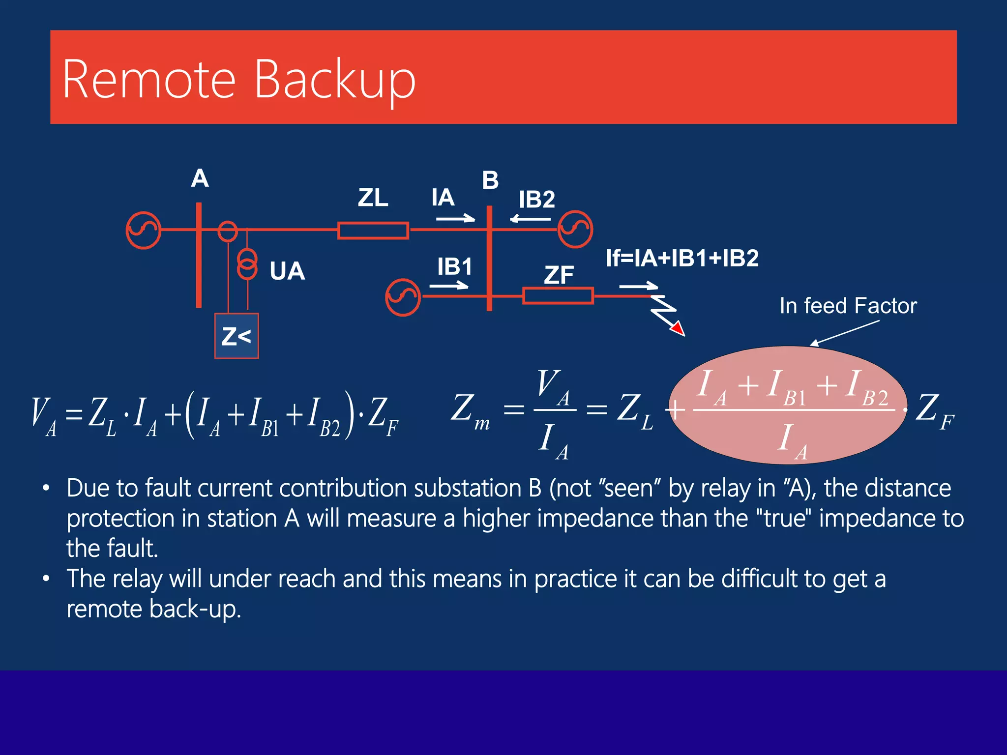

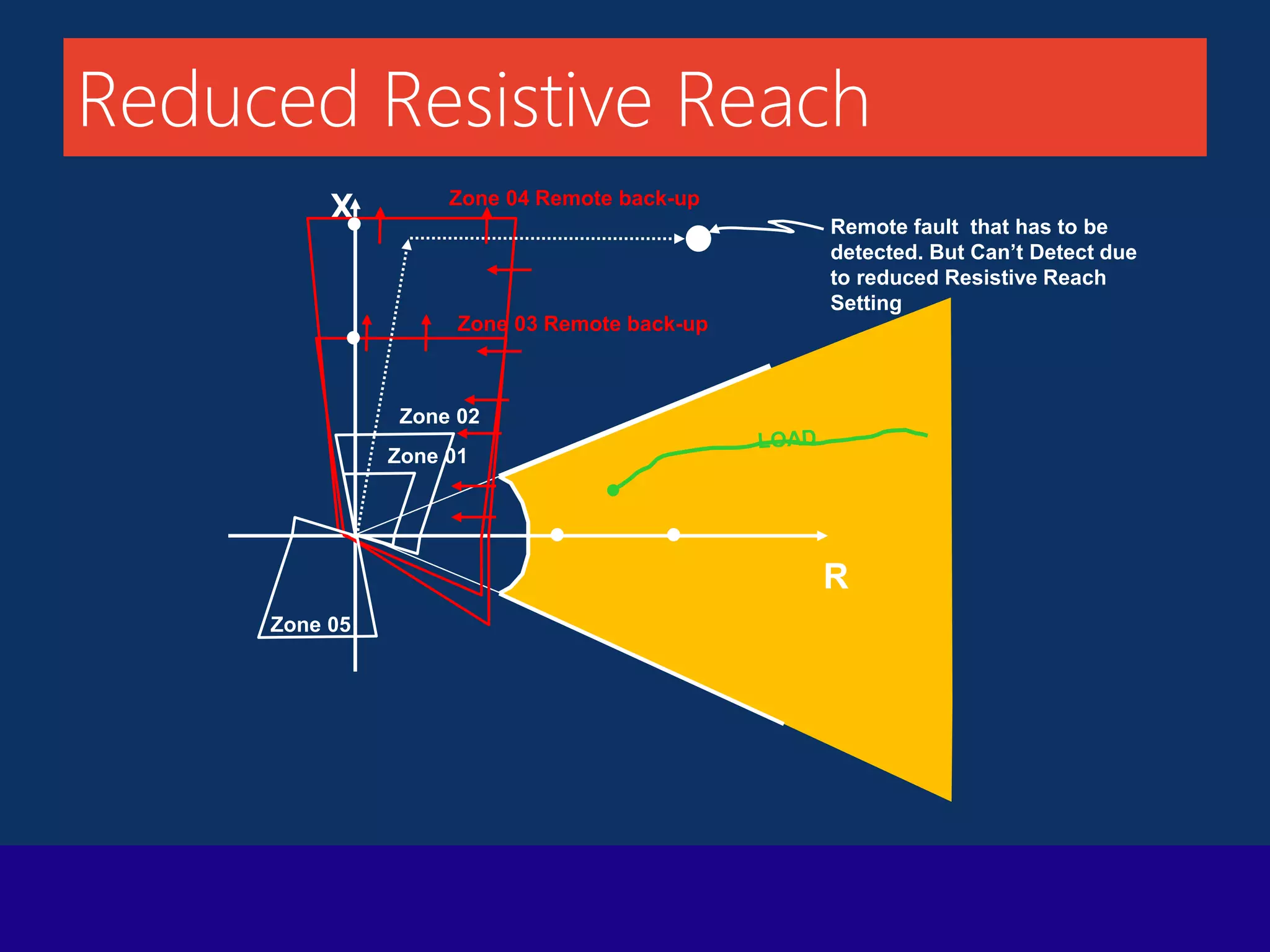
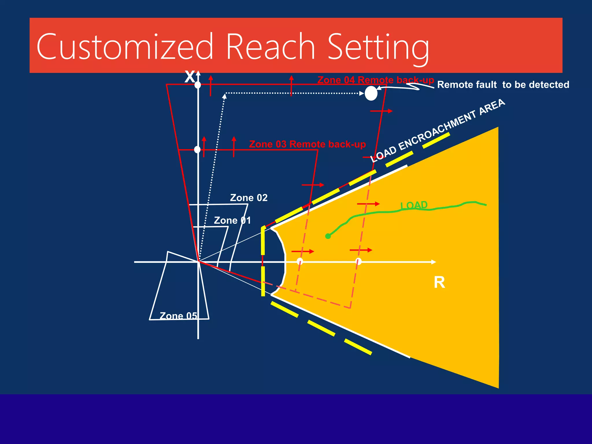
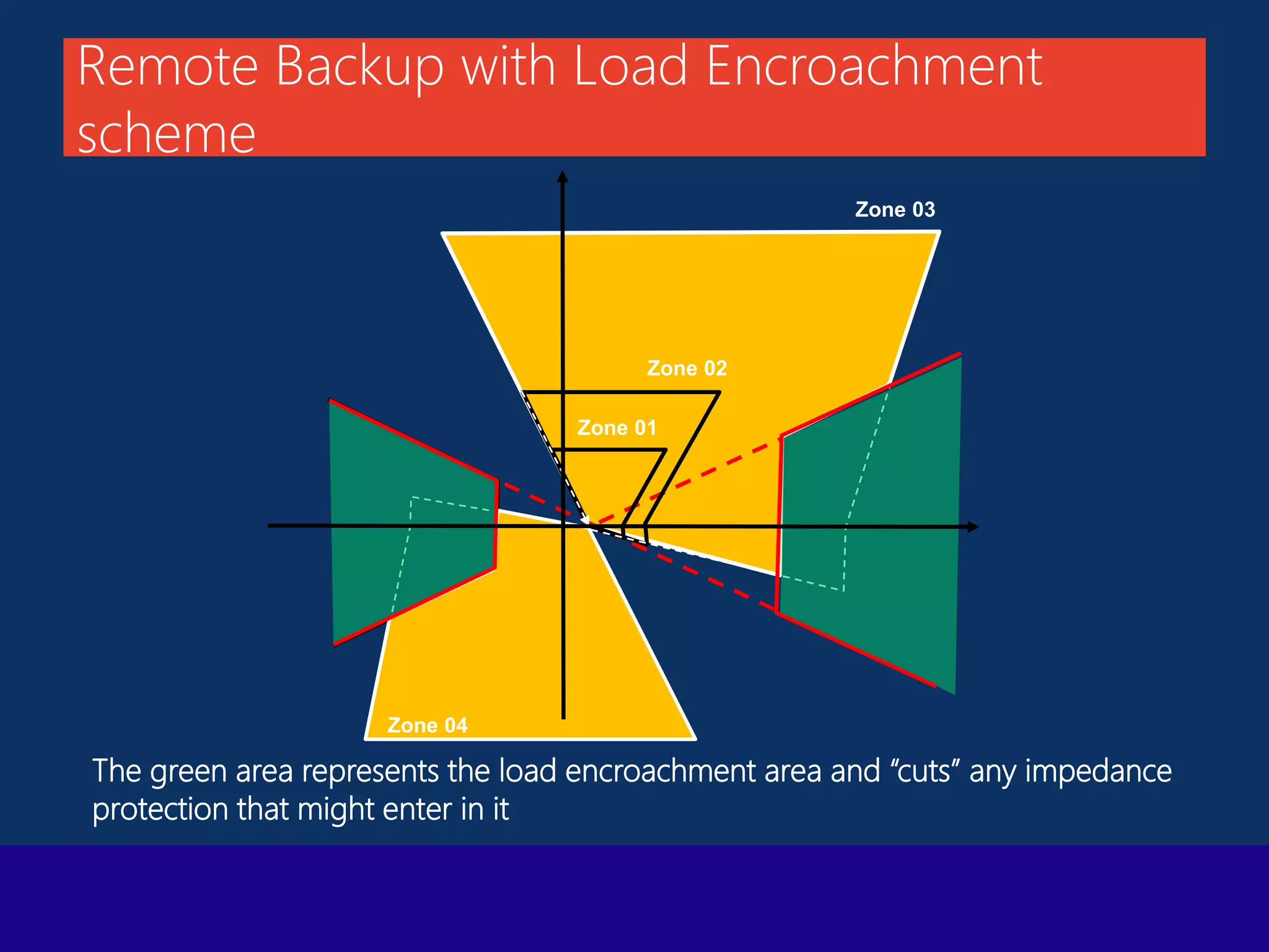


The document presents a technical overview of distance protection in electrical systems, detailing the principles, characteristics, and operational parameters of various protective zones. It covers relay performance, fault simulations, and the impact of resistive faults, emphasizing the importance of accurate reach settings and load encroachment considerations for effective fault detection. Additionally, it includes a discussion on remote backup strategies and the influence of fault resistance on distance protection performance.


![protection of transmission lines[distance relay protection scheme]](https://cdn.slidesharecdn.com/ss_thumbnails/os-exe3-23-may2011-sr-i-776s21tr-lineprotection-120425095503-phpapp02-thumbnail.jpg?width=640&height=640&fit=bounds)


