1. Distance protection provides fast primary and backup protection for transmission lines using impedance-based relaying. It can easily coordinate with autoreclosing and has operating times much less than overcurrent schemes.
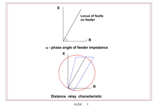
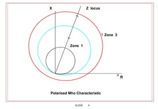
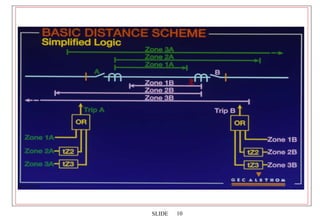
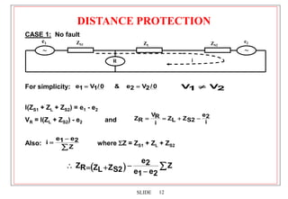
2. Distance relays use characteristics like mho circles to compare the measured impedance of a fault to the known impedances of zones along the transmission line. This allows them to discriminate faults in each zone and provide selective tripping.
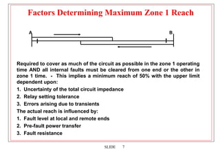
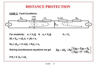
3. Factors like mutual coupling between phases, fault resistance, and multiple fault infeeds can affect the measured impedance and require compensation techniques in distance relays.


![16
SLIDE
EXAMPLE
Consider a radial feeder of 16km and 0·31 /84º /km connected to a
source of 5000MVA at a potential of 275kV. Find the phase-phase
relay voltage, if the VT ratio is 275kV/110V.
Solution
Source impedance ZS1 =
5000
2
275
= 15·13
Total line setting impedance ZL1 = 16 0·31 /84º = 4·96 /84º
(Primary)
System impedance ratio: SIR = ZS1/ZL1 =
96
4
13
15
= 3·05
Phase-phase fault current for a fault at reach point
IF =
)]
96
4
13
15
(
2
[
3
10
275
= 6844 Amp
The phase-phase relay voltage =
1)
05
(3
110
1)
(SIR
V
= 27·16V](https://image.slidesharecdn.com/slidessection9-distanceprotection-231018120326-249be1e9/85/Distance-Protection-ppt-16-320.jpg)
![17
SLIDE
F
)]
96
4
13
15
(
2
[
The phase-phase relay voltage =
1)
05
(3
110
1)
(SIR
V
= 27·16V
Alternatively: VR = IF 2 ZL1
275000
110
= 27·16V
The accurate reach of a distance relay depends on the minimum
voltage at the relay location. This voltage can be quoted in terms of
an equivalent maximum SIR. For instance, some distance relays
have a reach setting down to a voltage of 3·55 volts for a phase-
phase fault at the relay zone 1 reach point. This is equivalent to an
SIR of 30 for a relay rated at 100V phase to phase.
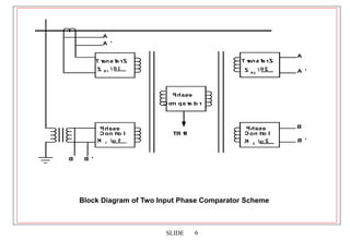
Most modern distance relays are fitted with sound phase
polarisation and/or memory characteristics, which allow them to
operate for a close-up fault when the relay fault voltage may be very
small.](https://image.slidesharecdn.com/slidessection9-distanceprotection-231018120326-249be1e9/85/Distance-Protection-ppt-17-320.jpg)


![protection of transmission lines[distance relay protection scheme]](https://cdn.slidesharecdn.com/ss_thumbnails/os-exe3-23-may2011-sr-i-776s21tr-lineprotection-120425095503-phpapp02-thumbnail.jpg?width=640&height=640&fit=bounds)