DISTANCE RELAY
The impedancerelays also called distance relays are
employed to provide protection to transmission lines
connected in a network
A distance relay, as its name implies, has the ability to
detect a fault within a pre-set distance along a
transmission line or power cable from its location.
The impedance relay is made to respond to the
impedance between the relay location and the point
where fault is incident.
2
3.
DISTANCE RELAY
The impedanceis proportional to the distance to the
fault, and is therefore independent of the fault current
levels.
Power line has a resistance and reactive per kilometer
related to its design and construction so its total
impedance will be a function of its length or distance.
A distance relay, looks at current and voltage and
compares these two quantities on the basis of Ohm’s
law.
3
4.
Principle of operationof distance relay
A distance relay compares the currents and voltages at the
relaying point with Current providing the operating torque and
the voltage provides the restraining torque.
In other words an impedance relay is a voltage restrained
overcurrent relay.
Since the operating characteristics of the relay depend upon
the ratio of voltage and current and the phase angle between
them, their characteristics can be best represented on an R-X
diagram where both V/I ratio and the phase angle can be
plotted in terms of an impedance R+jX.
4
5.
Principle of operationof distance relay
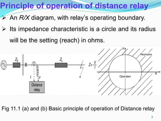
An R/X diagram, with relay’s operating boundary.
Its impedance characteristic is a circle and its radius
will be the setting (reach) in ohms.
Fig 11.1 (a) and (b) Basic principle of operation of Distance relay
5
6.
Principle of operationof distance relay
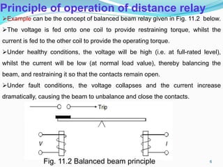
Example can be the concept of balanced beam relay given in Fig. 11.2 below.
The voltage is fed onto one coil to provide restraining torque, whilst the
current is fed to the other coil to provide the operating torque.
Under healthy conditions, the voltage will be high (i.e. at full-rated level),
whilst the current will be low (at normal load value), thereby balancing the
beam, and restraining it so that the contacts remain open.
Under fault conditions, the voltage collapses and the current increase
dramatically, causing the beam to unbalance and close the contacts.
Fig. 11.2 Balanced beam principle 6
7.
Principle of operationof distance relay
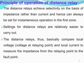
The distance relays achieve selectivity on the basis of
impedance rather than current and hence can always
be set for instantaneous operation in the first zone.
Settings for distance relays are relatively easier to
carry out.
The distance relays, thus, basically compare local
voltage (voltage at relaying point) and local current to
measure the impedance from the relaying point to the
fault point.
7
8.
Principle of operationof distance relay
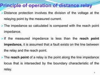
Distance protection involves the division of the voltage at the
relaying point by the measured current.
The impedance so calculated is compared with the reach point
impedance.
If the measured impedance is less than the reach point
impedance, it is assumed that a fault exists on the line between
the relay and the reach point.
The reach point of a relay is the point along the line impedance
locus that is intersected by the boundary characteristic of the
relay.
8
9.
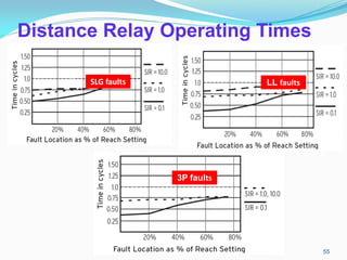
RELAY PERFORMANCE
Distance relayperformance is defined in terms of
reach accuracy and operating time.
Reach accuracy is a comparison of the actual ohmic
reach of the relay under practical conditions with the
relay setting value in ohms.
Reach accuracy particularly depends on the level of
voltage presented to the relay under fault conditions.
9
10.
RELAY PERFORMANCE
Depending onthe measuring techniques employed,
measuring signal transient errors, such as those
produced by Capacitor Voltage Transformers (CVT) or
saturating CT’s, can also adversely delay relay
operation for faults close to the reach point.
It is usual for electromechanical and static distance
relays to claim both maximum and minimum
operating times.
10
11.
STEPPED DISTANCE CHARACTERISTICSOF A DISTANCE
RELAY
The distance measurement can be done either by an
amplitude comparator or by a phase comparator.
The basic constructional unit representing an
amplitude comparator is a balanced beam relay.
Similarly, an induction cup relay is a phase comparator.
A distance relay has three zones of protection as
shown in Fig. 11.3(a).
The first zone (zone 1) covers about 80% to 85% of
the section to be protected. 11
12.
STEPPED DISTANCE CHARACTERISTICSOF A DISTANCE
RELAY
The resulting 15% - 20% safety margin ensures that
there is no risk of the Zone 1 protection over-reaching
the protected line due to errors in the current and
voltage transformers, inaccuracies in line impedance
data provided for setting purposes and errors of relay
setting and measurement.
Otherwise, it may lead to a loss of discrimination with
fast operating protection on the Zone 2 of the distance
protection covering the remaining 15% - 20% of the
12
13.
STEPPED DISTANCE CHARACTERISTICSOF A DISTANCE
RELAY
A distance relay operates instantaneously if the fault occurs in
the first zone (zone 1).
The second zone (zone 2) covers at least 120% of the
protected line impedance.
In many applications it is common practice to set the Zone 2
reach to be equal to the protected line section +50% of the
shortest adjacent line.
The same distance relay operates after a pre-set time delay if
the fault occurs in the second zone of protection of the relay.
13
14.
STEPPED DISTANCE CHARACTERISTICSOF A DISTANCE
RELAY
Where possible, this ensures that the resulting
maximum effective Zone 2 reach does not extend
beyond the minimum effective Zone 1 reach of the
adjacent line protection.
This avoids the need to grade the Zone 2 time
settings between upstream and downstream relays.
Remote back-up protection for all faults on adjacent
lines can be provided by a third zone (Zone 3) of
protection. 14
15.
STEPPED DISTANCE CHARACTERISTICSOF A DISTANCE
RELAY
This is a time delayed to discriminate with Zone 2
protection plus circuit breaker trip time for the adjacent
line.
Zone 3 reach should be set to at least 1.2 times the
impedance presented to the relay for a fault at the
remote end of second line section.
This zone is invariably added as a starter element and
this takes the form of an offset mho characteristic.
15
16.
The short backwardreach also provides local backup
for a busbar fault.
It is important that when setting a distance relays,
especially zone 3, which has the longest reach, that its
characteristic does not encroach on the load area, as
unnecessary tripping will undoubtedly occur.
16
Fig. 11.3 Three zone MHO characteristics
17.
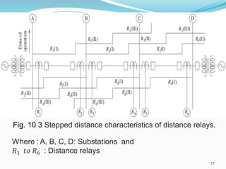
Fig. 10 3Stepped distance characteristics of distance relays.
17
18.
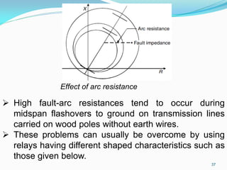
Effect of arcresistance
Resistance of the fault arc can also have an impact
on the performance of a distance relay.
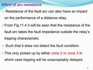
From Fig.11.4 it will be seen that the resistance of the
fault arc takes the fault impedance outside the relay’s
tripping characteristic.
Such that it does not detect the fault condition.
This only picked up by either zone 2 or zone 3 in
which case tripping will be unacceptably delayed.
18
19.
Effect of arcresistance
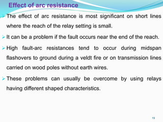
The effect of arc resistance is most significant on short lines
where the reach of the relay setting is small.
It can be a problem if the fault occurs near the end of the reach.
High fault-arc resistances tend to occur during midspan
flashovers to ground during a veldt fire or on transmission lines
carried on wood poles without earth wires.
These problems can usually be overcome by using relays
having different shaped characteristics.
19
20.
Transmission Lines
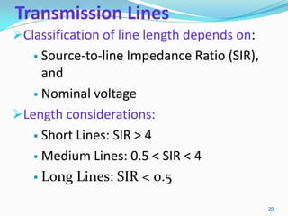
Classification ofline length depends on:
Source-to-line Impedance Ratio (SIR),
and
Nominal voltage
Length considerations:
Short Lines: SIR > 4
Medium Lines: 0.5 < SIR < 4
Long Lines: SIR < 0.5
20
Typical Protection Schemes
MediumLines
Phase comparison
Directional Comparison Blocking (DCB)
Permissive Underreach Transfer Trip (PUTT)
Permissive Overreach Transfer Trip (POTT)
Unblocking
Step Distance
Step or coordinated overcurrent
Inverse time overcurrent
Current Differential
22
23.
Typical Protection Schemes
LongLines
• Phase comparison
• Directional Comparison Blocking (DCB)
• Permissive Underreach Transfer Trip (PUTT)
• Permissive Overreach Transfer Trip (POTT)
• Unblocking
• Step Distance
• Step or coordinated overcurrent
• Current Differential 23
24.
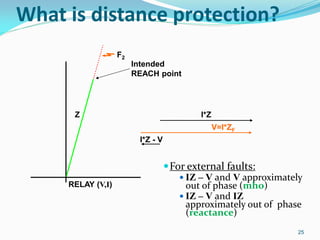
What is distanceprotection?
For internal faults:
IZ – V and V approximately in
phase (mho)
IZ – V and IZ
approximately in phase
(reactance)
RELAY (V,I)
Intended
REACH point
Z
F1
I*Z
V=I*ZF
I*Z - V
24
25.
What is distanceprotection?
For external faults:
IZ – V and V approximately
out of phase (mho)
IZ – V and IZ
approximately out of phase
(reactance)
RELAY (V,I)
Intended
REACH point
Z I*Z
V=I*ZF
I*Z - V
F2
25
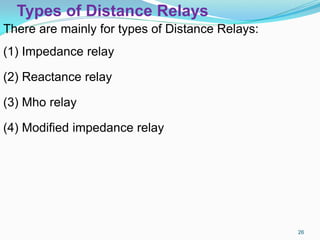
26.
Types of DistanceRelays
There are mainly for types of Distance Relays:
(1) Impedance relay
(2) Reactance relay
(3) Mho relay
(4) Modified impedance relay
26
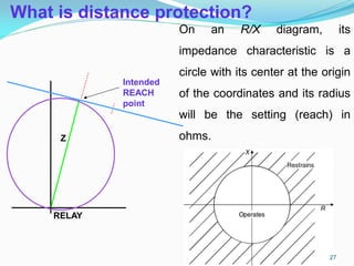
27.
What is distanceprotection?
RELAY
Intended
REACH
point
Z
On an R/X diagram, its
impedance characteristic is a
circle with its center at the origin
of the coordinates and its radius
will be the setting (reach) in
ohms.
27
28.
The relay willoperate for all values less than its
setting i.e. all points within the circle.
This is known as a plain impedance relay and it is
non-directional, in that it can operate for faults behind
the relaying point and no account of the phase angle
between voltage and current.
This limitation can be overcome by a technique
known as self-polarization. Additional voltages are
fed into the comparator in order to compare the
relative phase angles of voltage and current, so
providing a directional feature.
This has the effect of moving the circle such that the
circumference of the circle now passes through the
origin. Angle () is known as the relay’s characteristic
angle. 28
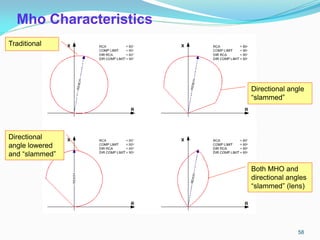
29.
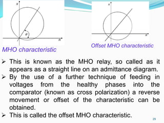
This isknown as the MHO relay, so called as it
appears as a straight line on an admittance diagram.
By the use of a further technique of feeding in
voltages from the healthy phases into the
comparator (known as cross polarization) a reverse
movement or offset of the characteristic can be
obtained.
This is called the offset MHO characteristic.
Offset MHO characteristic
MHO characteristic
29
30.
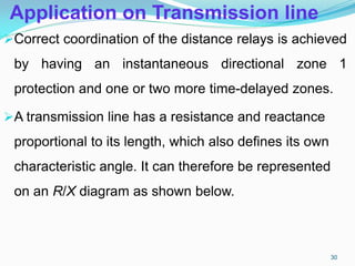
Application on Transmissionline
Correct coordination of the distance relays is achieved
by having an instantaneous directional zone 1
protection and one or two more time-delayed zones.
A transmission line has a resistance and reactance
proportional to its length, which also defines its own
characteristic angle. It can therefore be represented
on an R/X diagram as shown below.
30
31.
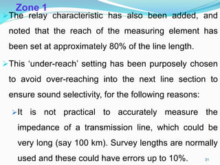
Zone 1
The relaycharacteristic has also been added, and
noted that the reach of the measuring element has
been set at approximately 80% of the line length.
This ‘under-reach’ setting has been purposely chosen
to avoid over-reaching into the next line section to
ensure sound selectivity, for the following reasons:
It is not practical to accurately measure the
impedance of a transmission line, which could be
very long (say 100 km). Survey lengths are normally
used and these could have errors up to 10%. 31
32.
Errors are alsopresent in the current and voltage
transformers, not to mention the possible transient
performance of these items.
Zone 1 MHO characteristic
32
33.
Zone 2
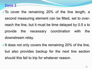
To coverthe remaining 20% of the line length, a
second measuring element can be fitted, set to over-
reach the line, but it must be time delayed by 0.5 s to
provide the necessary coordination with the
downstream relay.
It does not only covers the remaining 20% of the line,
but also provides backup for the next line section
should this fail to trip for whatever reason.
33
34.
Zone 3
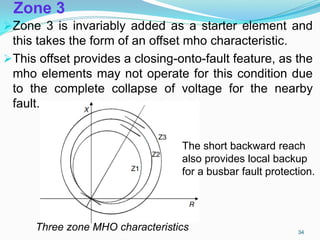
Zone 3is invariably added as a starter element and
this takes the form of an offset mho characteristic.
This offset provides a closing-onto-fault feature, as the
mho elements may not operate for this condition due
to the complete collapse of voltage for the nearby
fault.
Three zone MHO characteristics
The short backward reach
also provides local backup
for a busbar fault protection.
34
35.
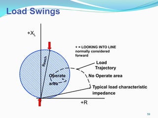
Effect of loadcurrent
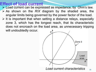
Load current can be expressed as impedance, by Ohm’s law.
As shown on the R/X diagram by the shaded area, the
angular limits being governed by the power factor of the load.
It is important that when setting a distance relays, especially
zone 3, which has the longest reach, that its characteristic
does not encroach on the load area, as unnecessary tripping
will undoubtedly occur.
Load current characteristics 35
36.
Effect of arcresistance
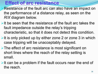
Resistance of the fault arc can also have an impact on
the performance of a distance relay, as seen on the
R/X diagram below.
It be seen that the resistance of the fault arc takes the
fault impedance outside the relay’s tripping
characteristic, so that it does not detect this condition.
It is only picked up by either zone 2 or zone 3 in which
case tripping will be unacceptably delayed.
The effect of arc resistance is most significant on
short lines where the reach of the relay setting is
small.
It can be a problem if the fault occurs near the end of
the reach.
36
37.
Effect of arcresistance
High fault-arc resistances tend to occur during
midspan flashovers to ground on transmission lines
carried on wood poles without earth wires.
These problems can usually be overcome by using
relays having different shaped characteristics such as
those given below.
37
38.
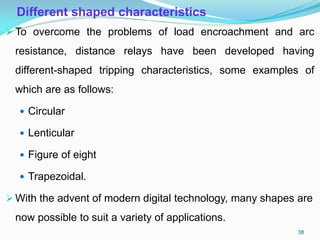
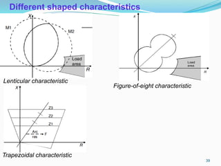
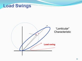
Different shaped characteristics
Toovercome the problems of load encroachment and arc
resistance, distance relays have been developed having
different-shaped tripping characteristics, some examples of
which are as follows:
Circular
Lenticular
Figure of eight
Trapezoidal.
With the advent of modern digital technology, many shapes are
now possible to suit a variety of applications.
38
Distance protection schemes
Dueto various zones, distance protection is strictly speaking not
a pure form of unit protection.
However, with the addition of an information link between the
two ends of the line, it can be made into a very effective unit
protection system.
This is achieved by installing a power line carrier signaling
channel between the two ends.
The signal is injected into the power line conductors at one end
via a capacitor voltage transformer and picked off the other end
by a similar device.
Line traps are installed at either end to prevent the signal
dispersing through all other lines, etc. in the network.
Other types of communication medium can be used such as
copper or fiber-optic pilots or microwave radio could be
considered if line-of-site is available.
40
41.
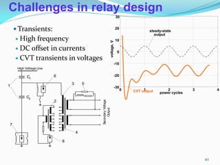
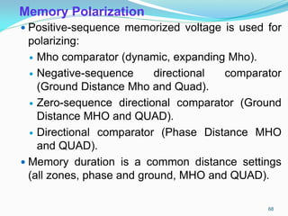
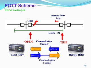
Challenges in relaydesign
Transients:
High frequency
DC offset in currents
CVT transients in voltages
CVT output
0 1 2 3 4
steady-state
output
power cycles
-30
-20
-10
0
10
20
30
voltage,
V
C1
C2
2
3 5
6
1
4
7
High Voltage Line
Secondary
Voltage
Output
8
41
42.
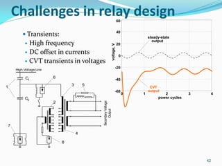
Challenges in relaydesign
Transients:
High frequency
DC offset in currents
CVT transients in voltages
C1
C2
2
3 5
6
1
4
7
High Voltage Line
Secondary
Voltage
Output
8
CVT
output
0 1 2 3 4
steady-state
output
-60
-40
-20
0
20
40
power cycles
voltage,
V
60
42
Transient Overreach
Faultcurrent generally contains dc offset in
addition to ac power frequency component.
Ratio of dc to ac component of current
depends on instant in the cycle at which
fault occurred.
Rate of decay of dc offset depends on
system X/R.
44
45.
Zone 1 andCVT Transients
Capacitive Voltage Transformers (CVTs) create
certain problems for fast distance relays applied to
systems with high Source Impedance Ratios
(SIRs):
CVT-induced transient voltage components may
assume large magnitudes (up to 30-40%) and
last for a comparatively long time (up to about 2
cycles)
60Hz voltage for faults at the relay reach point
may be as low as 3% for a SIR of 30
the signal may be buried under noise
45
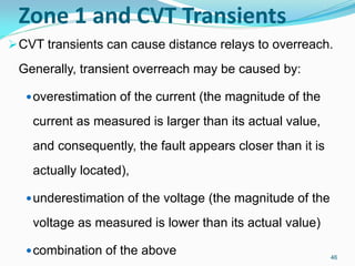
46.
Zone 1 andCVT Transients
CVT transients can cause distance relays to overreach.
Generally, transient overreach may be caused by:
overestimation of the current (the magnitude of the
current as measured is larger than its actual value,
and consequently, the fault appears closer than it is
actually located),
underestimation of the voltage (the magnitude of the
voltage as measured is lower than its actual value)
combination of the above 46
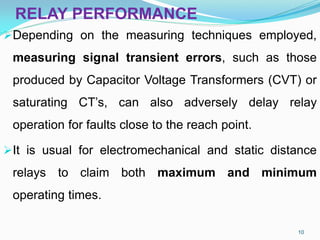
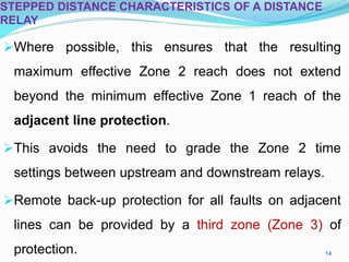
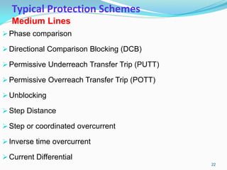
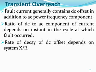
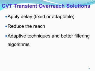
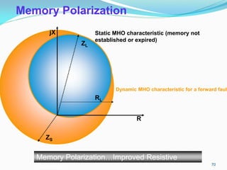
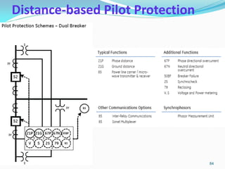
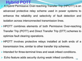
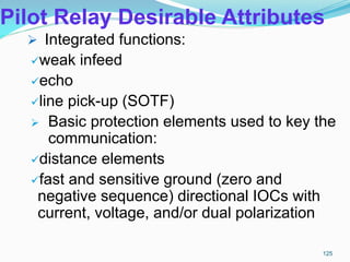
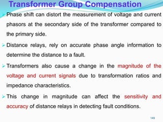
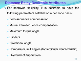
-10 -5 05 10
-5
0
5
10
15
Reactance
[ohm]
Resistance [ohm]
18
22
26
30
34
42
44 Actual Fault
Location
Line
Impedance
Trajectory
(msec)
dynamic mho
zone extended
for high SIRs
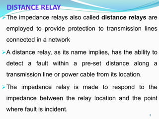
Impedance locus may pass
below the origin of the Z-plane -
this would call for a time delay
to obtain stability 48
49.
CVT Transient OverreachSolutions
Apply delay (fixed or adaptable)
Reduce the reach
Adaptive techniques and better filtering
algorithms
49
50.
CVT Transients –Adaptive Solution
Optimize signal filtering:
currents - max 3% error due to the dc
component
voltages - max 0.6% error due to CVT
transients
Adaptive double-reach approach
filtering alone ensures maximum transient
overreach at the level of 1% (for SIRs up to 5)
and 20% (for SIRs up to 30)
to reduce the transient overreach even further
an adaptive double-reach zone 1 has been
implemented. 50
51.
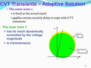
CVT Transients –Adaptive Solution
The outer zone 1:
is fixed at the actual reach
applies certain security delay to cope with CVT
transients
Delayed
Trip
Instantaneous
Trip
R
X
The inner zone 1:
> has its reach dynamically
controlled by the voltage
magnitude
> is instantaneous
51
52.
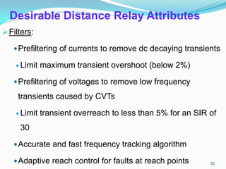
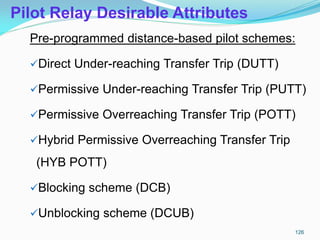
Desirable Distance RelayAttributes
Filters:
Prefiltering of currents to remove dc decaying transients
Limit maximum transient overshoot (below 2%)
Prefiltering of voltages to remove low frequency
transients caused by CVTs
Limit transient overreach to less than 5% for an SIR of
30
Accurate and fast frequency tracking algorithm
Adaptive reach control for faults at reach points 52
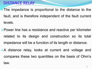
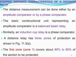
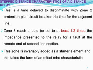
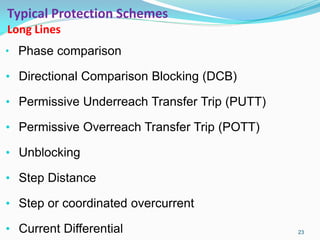
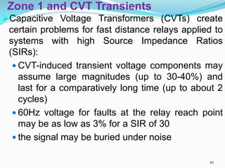
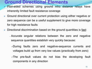
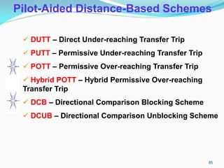
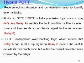
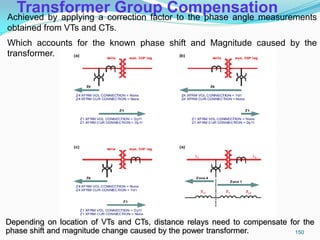
0 5 1015 20 25 30
0
10
20
30
40
50
60
70
80
90
100
Maximum
Rach
[%]
SIR
Actual maximum reach curves
Relay 1
Relay 3
Relay 2
Relay 4
56
57.
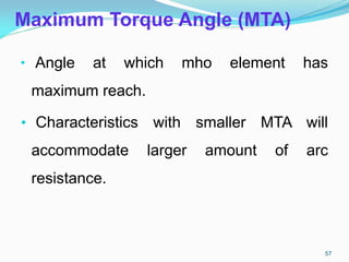
Maximum Torque Angle(MTA)
• Angle at which mho element has
maximum reach.
• Characteristics with smaller MTA will
accommodate larger amount of arc
resistance.
57
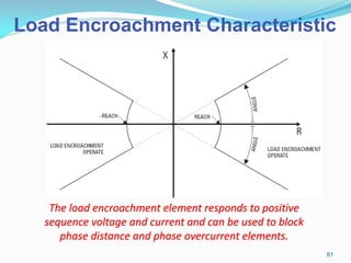
Load Encroachment Characteristic
Theload encroachment element responds to positive
sequence voltage and current and can be used to block
phase distance and phase overcurrent elements.
61
62.
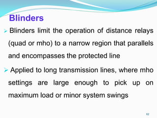
Blinders
Blinders limitthe operation of distance relays
(quad or mho) to a narrow region that parallels
and encompasses the protected line
Applied to long transmission lines, where mho
settings are large enough to pick up on
maximum load or minor system swings
62
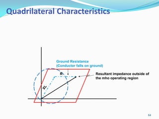
Mho Quadrilatera
l
Better coveragefor
ground faults due
to resistance added
to return path
Lenticular
Used for phase elements
with long heavily loaded
lines heavily loaded
Standard for phase
elements
JX
R
Distance Characteristics - Summary
65
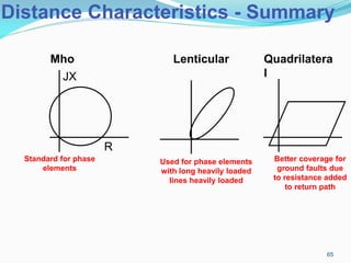
66.
Distance Element Polarization
Distance Element Polarization is a method used to polarize (or bias) the
operation of impedance elements within distance relays.
Distance element polarization refers to a setting adjustment in distance
protection relays used in power systems.
Polarization quantities commonly used in distance relays for determining
directionality:
• Self-polarized
• Memory voltage
• Positive sequence voltage
• Quadrature voltage
• Leading phase voltage
66
67.
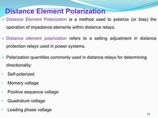
Self-polarized
A self-polarized relayis a type of protective relay that
determines the direction of a fault based on the phase
relationship between voltage and current signals
measured at its terminals.
Self-polarization in protective relays is to ensure that the relay
can accurately determine whether a fault is within its protected
zone (forward fault) or outside (reverse fault).
67
68.
Memory Polarization
Positive-sequencememorized voltage is used for
polarizing:
Mho comparator (dynamic, expanding Mho).
Negative-sequence directional comparator
(Ground Distance Mho and Quad).
Zero-sequence directional comparator (Ground
Distance MHO and QUAD).
Directional comparator (Phase Distance MHO
and QUAD).
Memory duration is a common distance settings
(all zones, phase and ground, MHO and QUAD).
68
69.
Memory Polarization
jX
R
Dynamic MHOcharacteristic for a reverse fault
Dynamic MHO characteristic for a forward
fault
Impedance During Close-up Faults
Static MHO characteristic (memory not established or
expired)
ZL
ZS
69
70.
Memory Polarization
Memory Polarization…ImprovedResistive
Coverage
Dynamic MHO characteristic for a forward fault
Static MHO characteristic (memory not
established or expired)
jX
R
ZL
ZS
RL
70
71.
Choice of Polarization
Inorder to provide flexibility modern
distance relays offer a choice with respect
to polarization of ground overcurrent
direction functions:
Voltage polarization
Current polarization
Dual polarization
71
72.
Ground Directional Elements
Pilot-aided schemes using ground mho distance relays have
inherently limited fault resistance coverage
Ground directional over current protection using either negative or
zero sequence can be a useful supplement to give more coverage
for high resistance faults
Directional discrimination based on the ground quantities is fast:
– Accurate angular relations between the zero and negative
sequence quantities establish very quickly because:
During faults zero and negative-sequence currents and
voltages build up from very low values (practically from zero)
The pre-fault values do not bias the developing fault
components in any direction
72
73.
Distance Schemes
Pilot AidedSchemes
No Communication between
Distance Relays
Communication between
Distance relays
Non-Pilot Aided Schemes
(Step Distance)
73
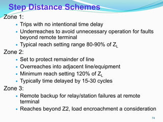
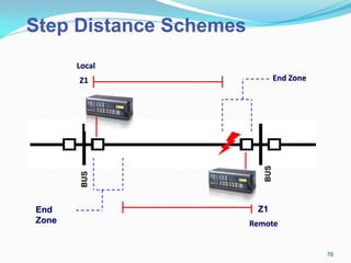
74.
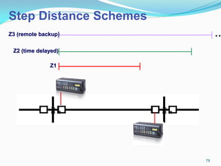
Step Distance Schemes
Zone1:
Trips with no intentional time delay
Underreaches to avoid unnecessary operation for faults
beyond remote terminal
Typical reach setting range 80-90% of ZL
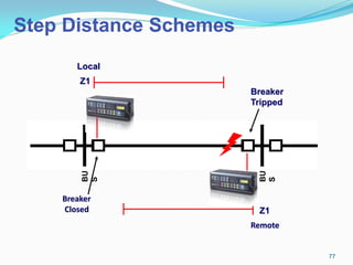
Zone 2:
Set to protect remainder of line
Overreaches into adjacent line/equipment
Minimum reach setting 120% of ZL
Typically time delayed by 15-30 cycles
Zone 3:
Remote backup for relay/station failures at remote
terminal
Reaches beyond Z2, load encroachment a consideration
74
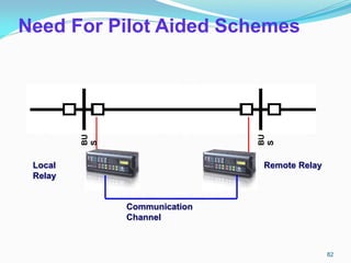
Pilot Communications Channels
Distance-basedpilot schemes traditionally
utilize simple on/off communications between
relays, but can also utilize peer-to-peer
communications and GOOSE messaging over
digital channels
Typical communications media include:
Pilot-wire (50Hz, 60Hz, AT)
Power line carrier
Microwave
Radio
Optic fiber (directly connected or
multiplexed channels)
83
Pilot-Aided Distance-Based Schemes
DUTT – Direct Under-reaching Transfer Trip
PUTT – Permissive Under-reaching Transfer Trip
POTT – Permissive Over-reaching Transfer Trip
Hybrid POTT – Hybrid Permissive Over-reaching
Transfer Trip
DCB – Directional Comparison Blocking Scheme
DCUB – Directional Comparison Unblocking Scheme
85
86.
Direct Underreaching TransferTrip (DUTT)
A DUTT is a protective relay scheme used in power systems to
facilitate fast and coordinated tripping of circuit breakers to
isolate faults.
This scheme is typically employed in interconnected power
systems where transmission lines span across different utility
companies or regions.
In a DUTT scheme, each end of a transmission line is
protected by distance relays (or other types of relays capable
of measuring fault impedance).
These relays are set to trip the circuit breaker at their
respective ends if a fault occurs within their reach zone.
86
87.
Direct Under reachingTransfer Trip (DUTT)
When a relay detects a fault within its reach zone, it sends a trip
signal directly to the remote relay at the opposite end of the line
via a communication channel.
Under-reaching Logic: The "under-reaching" part of DUTT
refers to the fact that the relay at one end of the line (let's call it
Relay A) will initiate a trip signal even if the fault is beyond its
own reach, relying on the coordination and confirmation from
the remote relay (Relay B) at the other end of the line.
87
88.
Direct Under reachingTransfer Trip (DUTT)
Trip Signal Transmission: Upon detecting a fault, Relay A sends
a trip signal to Relay B through the communication channel.
Relay B then verifies the fault within its own reach zone and
initiates tripping of the circuit breaker at its end if necessary.
Advantages: DUTT improves the speed and reliability of fault
clearing by allowing the remote end of the transmission line to
initiate breaker tripping based on the confirmation received from
the local end.
This coordination ensures that faults are isolated swiftly,
minimizing disruption to the power system and reducing the
likelihood of cascading failures. 88
89.
Direct Under reachingTransfer Trip (DUTT)
only under reaching (RU) functions which overlap in reach (Zone 1).
Applied with Frequency Shift Keying (FSK): is a modulation technique used
to transmit digital signals over communication channels.
GUARD frequency transmitted during normal conditions
TRIP frequency when one RU function operates
Scheme does not provide tripping for faults beyond RU reach if remote
breaker is open or channel is inoperative.
Dual pilot channels improve security
Modern digital relays facilitate DUTT through various communication
methods such as fiber optics, microwave links, or digital pilot wires.
These communication channels ensure rapid and reliable transmission of trip
signals between the relays.
89
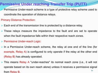
Permissive Under reachingTransfer Trip (PUTT)
Permissive Under-reach scheme is a type of protective relay scheme used to
coordinate the operation of distance relays.
Primary Distance Protection:
Each end of the transmission line is protected by a distance relay.
These relays measure the impedance to the fault and are set to operate
when the fault impedance falls within their respective reach zones.
Permissive Under-reach Logic:
In a Permissive Under-reach scheme, the relay at one end of the line (for
example, Relay A) is configured to only operate if the relay at the other end
(Relay B) has already operated.
This means Relay A "under-reaches" its normal reach zone (i.e., it will not
operate based on its own reach alone) unless it receives a permissive signal
from Relay B.
91
92.
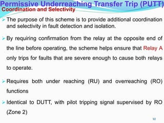
Permissive Underreaching TransferTrip (PUTT)
Coordination and Selectivity
The purpose of this scheme is to provide additional coordination
and selectivity in fault detection and isolation.
By requiring confirmation from the relay at the opposite end of
the line before operating, the scheme helps ensure that Relay A
only trips for faults that are severe enough to cause both relays
to operate.
Requires both under reaching (RU) and overreaching (RO)
functions
Identical to DUTT, with pilot tripping signal supervised by RO
(Zone 2)
92
93.
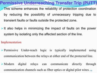
Permissive Underreaching TransferTrip (PUTT)
This scheme enhances the reliability of protection coordination
by reducing the possibility of unnecessary tripping due to
transient faults or faults outside the protected zone.
It also helps in minimizing the impact of faults on the power
system by isolating only the affected section of the line.
Implementation
Permissive Under-reach logic is typically implemented using
communication between the relays at either end of the protected line.
Modern digital relays can communicate directly through
communication channels such as fiber optics or digital pilot wires. 93
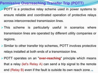
Permissive Overreaching TransferTrip (POTT)
POTT is a protective relay scheme used in power systems to
ensure reliable and coordinated operation of protective relays
across interconnected transmission lines.
This scheme is particularly useful in scenarios where
transmission lines are operated by different utility companies or
regions.
Similar to other transfer trip schemes, POTT involves protective
relays installed at both ends of a transmission line.
POTT operates on an "over-reaching" principle which means
that a relay (let's Relay A) can send a trip signal to the remote
end (Relay B) even if the fault is outside its own reach zone. 95
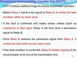
96.
Permissive Overreaching TransferTrip (POTT)
POTT involves additional logic to ensure coordinated operation.
Before Relay A sends a trip signal to Relay B, it verifies the fault
condition within its reach zone.
If the fault is confirmed and meets certain criteria (such as
impedance or fault type), Relay A will then send a permissive
signal to Relay B.
Once Relay B receives the permissive signal from Relay A, it
verifies the fault within its own reach zone.
If the fault condition is confirmed, Relay B initiates tripping of the
circuit breaker at its end of the transmission line. 96
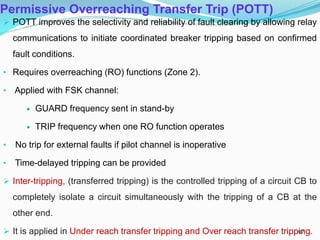
97.
Permissive Overreaching TransferTrip (POTT)
POTT improves the selectivity and reliability of fault clearing by allowing relay
communications to initiate coordinated breaker tripping based on confirmed
fault conditions.
• Requires overreaching (RO) functions (Zone 2).
• Applied with FSK channel:
GUARD frequency sent in stand-by
TRIP frequency when one RO function operates
• No trip for external faults if pilot channel is inoperative
• Time-delayed tripping can be provided
Inter-tripping, (transferred tripping) is the controlled tripping of a circuit CB to
completely isolate a circuit simultaneously with the tripping of a CB at the
other end.
It is applied in Under reach transfer tripping and Over reach transfer tripping.
97
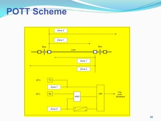
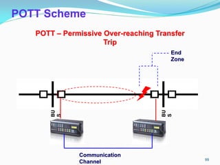
POTT Scheme
POTT –Permissive Over-reaching Transfer
Trip
End
Zone
Communication
Channel 99
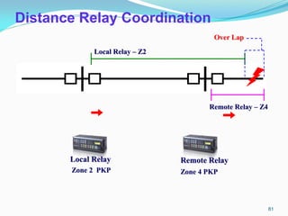
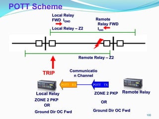
100.
Local Relay RemoteRelay
Remote
Relay FWD
IGND
Ground Dir OC Fwd
OR
Local Relay – Z2
ZONE 2 PKP
Local Relay
FWD IGND
Ground Dir OC Fwd
OR
TRIP
Remote Relay – Z2
POTT TX
ZONE 2 PKP
POTT RX
Communicatio
n Channel
POTT Scheme
100
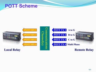
101.
POTT TX 4
POTTTX 3
POTT TX 2
POTT TX 1 A to G
B to G
C to G
Multi Phase
Local Relay Remote Relay
POTT RX 4
POTT RX 3
POTT RX 2
POTT RX 1
Communications
Channel(s)
POTT Scheme
101
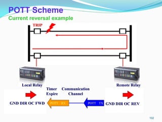
102.
Local Relay RemoteRelay
POTT TX ZONE 2 OR
GND DIR OC FWD
Communication
Channel
TRIP
GND DIR OC REV
GND DIR OC REV POTT RX
Start
Timer
Timer
Expire
GND DIR OC FWD
POTT Scheme
Current reversal example
102
103.
Local Relay
Open
Remote Relay
RemoteFWD
IGND
POTT TX
Remote – Z2
Communication
Channel
POTT RX
OPEN
POTT TX
Communication
Channel
POTT RX
TRIP
POTT Scheme
Echo example
103
104.
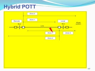
Hybrid POTT
AHybrid Permissive Over-reaching Transfer Trip (HPOTT) is an
advanced protective relay scheme used in power systems to
enhance the reliability and selectivity of fault detection and
isolation across interconnected transmission lines.
HPOTT combines elements of both Permissive Over-reaching
Transfer Trip (POTT) and Direct Transfer Trip (DTT) schemes to
optimize fault clearing operations.
HPOTT involves protective relays installed at both ends of a
transmission line, similar to other transfer trip schemes.
Intended for three-terminal lines and weak infeed conditions.
Echo feature adds security during weak infeed conditions. 104
105.
Hybrid POTT
Reverse-lookingdistance and oc elements used to identify
external faults.
Similar to POTT, HPOTT includes permissive logic where a relay
(let's say Relay A) verifies the fault condition within its reach
zone and then sends a permissive signal to the remote end
(Relay B).
HPOTT incorporates over-reaching logic which means that
Relay A can send a trip signal to Relay B even if the fault is
outside its own reach zone, but within the overall protected zone
covered by the relays.
105
106.
Hybrid POTT
Before RelayA sends a permissive signal to Relay B, it verifies
the fault condition within its reach zone.
If the fault meets certain criteria (impedance or fault type), Relay
A initiates the permissive signal to Relay B.
Upon receiving the permissive signal, Relay B verifies the fault
within its own reach zone and proceeds with tripping the circuit
breaker at its end if necessary.
HPOTT requires robust communication channels between the
protective relays, such as fiber optics, microwave links, or digital
pilot wires. 106
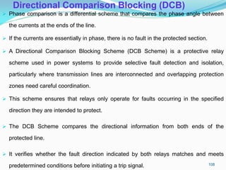
Directional Comparison Blocking(DCB)
Phase comparison is a differential scheme that compares the phase angle between
the currents at the ends of the line.
If the currents are essentially in phase, there is no fault in the protected section.
A Directional Comparison Blocking Scheme (DCB Scheme) is a protective relay
scheme used in power systems to provide selective fault detection and isolation,
particularly where transmission lines are interconnected and overlapping protection
zones need careful coordination.
This scheme ensures that relays only operate for faults occurring in the specified
direction they are intended to protect.
The DCB Scheme compares the directional information from both ends of the
protected line.
It verifies whether the fault direction indicated by both relays matches and meets
predetermined conditions before initiating a trip signal. 108
109.
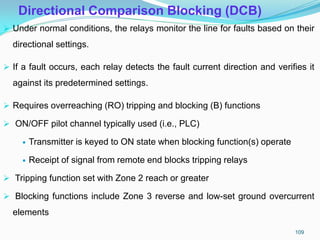
Directional Comparison Blocking(DCB)
Under normal conditions, the relays monitor the line for faults based on their
directional settings.
If a fault occurs, each relay detects the fault current direction and verifies it
against its predetermined settings.
Requires overreaching (RO) tripping and blocking (B) functions
ON/OFF pilot channel typically used (i.e., PLC)
Transmitter is keyed to ON state when blocking function(s) operate
Receipt of signal from remote end blocks tripping relays
Tripping function set with Zone 2 reach or greater
Blocking functions include Zone 3 reverse and low-set ground overcurrent
elements
109
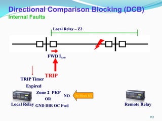
Directional Comparison Blocking(DCB)
Internal Faults
Local Relay Remote Relay
Local Relay – Z2
Zone 2 PKP
TRIP Timer
Start
FWD IGND
GND DIR OC Fwd
OR
Dir Block RX
NO
TRIP
Expired
112
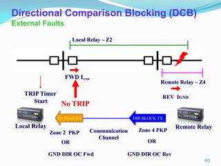
113.
Local Relay RemoteRelay
Remote Relay – Z4
Zone 4 PKP
REV IGND
GND DIR OC Rev
OR
DIR BLOCK TX
Local Relay – Z2
Zone 2 PKP
Dir Block RX
Communication
Channel
FWD IGND
GND DIR OC Fwd
OR
TRIP Timer
Start No TRIP
Directional Comparison Blocking (DCB)
External Faults
113
114.
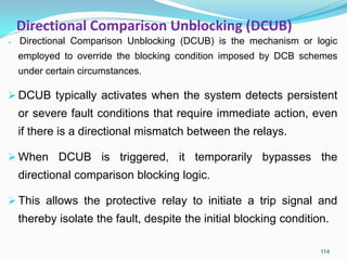
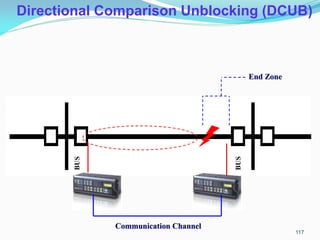
Directional Comparison Unblocking(DCUB)
Directional Comparison Unblocking (DCUB) is the mechanism or logic
employed to override the blocking condition imposed by DCB schemes
under certain circumstances.
DCUB typically activates when the system detects persistent
or severe fault conditions that require immediate action, even
if there is a directional mismatch between the relays.
When DCUB is triggered, it temporarily bypasses the
directional comparison blocking logic.
This allows the protective relay to initiate a trip signal and
thereby isolate the fault, despite the initial blocking condition.
114
115.
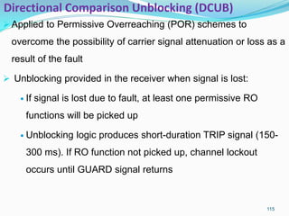
Directional Comparison Unblocking(DCUB)
Applied to Permissive Overreaching (POR) schemes to
overcome the possibility of carrier signal attenuation or loss as a
result of the fault
Unblocking provided in the receiver when signal is lost:
If signal is lost due to fault, at least one permissive RO
functions will be picked up
Unblocking logic produces short-duration TRIP signal (150-
300 ms). If RO function not picked up, channel lockout
occurs until GUARD signal returns
115
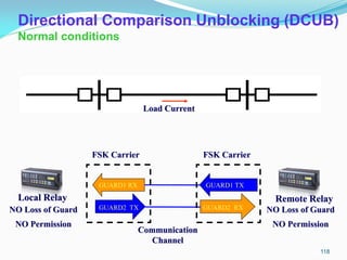
Directional Comparison Unblocking(DCUB)
Normal conditions
Local Relay Remote Relay
GUARD1 TX
GUARD1 RX
Communication
Channel
GUARD2 TX GUARD2 RX
NO Loss of Guard
FSK Carrier FSK Carrier
NO Permission
NO Loss of Guard
NO Permission
Load Current
118
119.
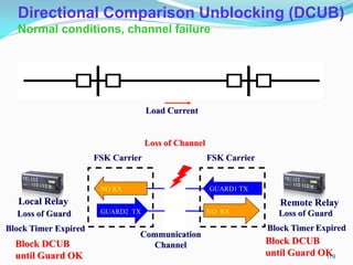
Directional Comparison Unblocking(DCUB)
Normal conditions, channel failure
Local Relay Remote Relay
GUARD1 TX
GUARD1 RX
Communication
Channel
GUARD2 TX GUARD2 RX
FSK Carrier FSK Carrier
Loss of Guard
Block Timer Started
Loss of Guard
Block Timer Started
Load Current
NO RX
NO RX
Block DCUB
until Guard OK
Expired
Block DCUB
until Guard OK
Expired
Loss of Channel
119
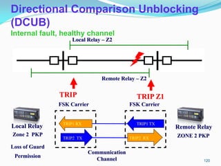
120.
Directional Comparison Unblocking
(DCUB)
Internalfault, healthy channel
Local Relay Remote Relay
GUARD1 TX
GUARD1 RX
Communication
Channel
GUARD2 TX GUARD2 RX
FSK Carrier FSK Carrier
Loss of Guard
Permission
TRIP1 TX
Local Relay – Z2
Zone 2 PKP
TRIP1 RX
TRIP2 TX
TRIP
Remote Relay – Z2
ZONE 2 PKP
TRIP Z1
TRIP2 RX
120
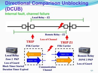
121.
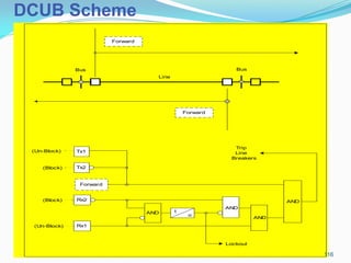
Directional Comparison Unblocking
(DCUB)
Internalfault, channel failure
Local Relay Remote Relay
GUARD1 TX
GUARD1 RX
Communication
Channel
GUARD2 TX GUARD2 RX
FSK Carrier FSK Carrier
TRIP1 TX
Local Relay – Z2
Zone 2 PKP
NO RX
TRIP2 TX
TRIP
Remote Relay – Z2
ZONE 2 PKP
TRIP Z1
NO RX
Loss of Guard
Loss of Channel
Loss of Guard
Block Timer Started
Duration Timer Started
Expired 121
122.
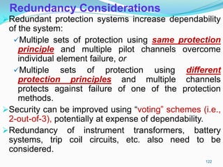
Redundancy Considerations
Redundant protectionsystems increase dependability
of the system:
Multiple sets of protection using same protection
principle and multiple pilot channels overcome
individual element failure, or
Multiple sets of protection using different
protection principles and multiple channels
protects against failure of one of the protection
methods.
Security can be improved using “voting” schemes (i.e.,
2-out-of-3), potentially at expense of dependability.
Redundancy of instrument transformers, battery
systems, trip coil circuits, etc. also need to be
considered.
122
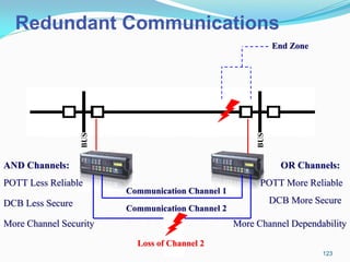
123.
End Zone
Communication Channel1
Communication Channel 2
Loss of Channel 2
AND Channels:
POTT Less Reliable
DCB Less Secure
OR Channels:
POTT More Reliable
DCB More Secure
More Channel Security More Channel Dependability
Redundant Communications
123
Pilot Relay DesirableAttributes
Integrated functions:
weak infeed
echo
line pick-up (SOTF)
Basic protection elements used to key the
communication:
distance elements
fast and sensitive ground (zero and
negative sequence) directional IOCs with
current, voltage, and/or dual polarization
125
126.
Pilot Relay DesirableAttributes
Pre-programmed distance-based pilot schemes:
Direct Under-reaching Transfer Trip (DUTT)
Permissive Under-reaching Transfer Trip (PUTT)
Permissive Overreaching Transfer Trip (POTT)
Hybrid Permissive Overreaching Transfer Trip
(HYB POTT)
Blocking scheme (DCB)
Unblocking scheme (DCUB)
126
127.
Security for dual-breakerterminals
Breaker-and-a-half and ring bus terminals
are common designs for transmission
lines.
Standard practice has been to:
sum currents from each circuit breaker
externally by paralleling the CTs
use external sum as the line current for
protective relays
For some close-in external fault events,
poor CT performance may lead to
improper operation of line relays.
127
128.
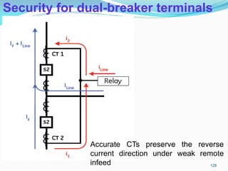
Security for dual-breakerterminals
Accurate CTs preserve the reverse
current direction under weak remote
infeed 128
129.
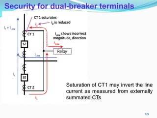
Security for dual-breakerterminals
Saturation of CT1 may invert the line
current as measured from externally
summated CTs
129
130.
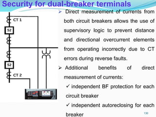
Security for dual-breakerterminals
Direct measurement of currents from
both circuit breakers allows the use of
supervisory logic to prevent distance
and directional overcurrent elements
from operating incorrectly due to CT
errors during reverse faults.
Additional benefits of direct
measurement of currents:
independent BF protection for each
circuit breaker
independent autoreclosing for each
breaker 130
131.
Security for dual-breakerterminals
Supervisory logic should:
Not affect speed or sensitivity of protection
elements
Correctly allow tripping during evolving external-to-
internal fault conditions
Determine direction of current flow through each
breaker independently:
Both currents in FWD direction internal fault
One current FWD, one current REV external
fault
Allow tripping during all forward/internal faults
Block tripping during all reverse/external faults
Initially block tripping during evolving external-to-
internal faults until second fault appears in forward
direction. Block is then lifted to permit tripping. 131
132.
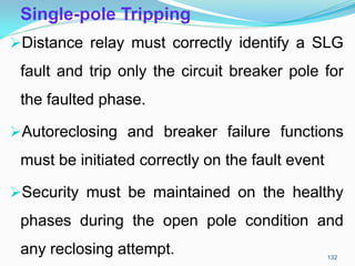
Single-pole Tripping
Distance relaymust correctly identify a SLG
fault and trip only the circuit breaker pole for
the faulted phase.
Autoreclosing and breaker failure functions
must be initiated correctly on the fault event
Security must be maintained on the healthy
phases during the open pole condition and
any reclosing attempt. 132
133.
Out-of-Step Condition
For certainoperating conditions, a severe
system disturbance can cause system
instability and result in loss of synchronism
between different generating units on an
interconnected system.
133
134.
Out-of-Step Relaying
Out-of-step blockingrelays
Operate in conjunction with mho tripping relays to prevent
a terminal from tripping during severe system swings &
out-of-step conditions.
Prevent system from separating in an indiscriminate
manner.
Out-of-step tripping relays
Operate independently of other devices to detect out-of-
step condition during the first pole slip.
Initiate tripping of breakers that separate system in order
to balance load with available generation on any isolated
part of the system.
134
135.
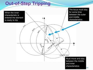
Out-of-Step Tripping
The locusmust stay
for some time
between the outer
and middle
characteristics
Must move and stay
between the middle
and inner
characteristics
When the inner
characteristic is
entered the element
is ready to trip
135
136.
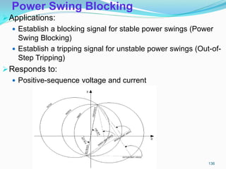
Power Swing Blocking
Applications:
Establish a blocking signal for stable power swings (Power
Swing Blocking)
Establish a tripping signal for unstable power swings (Out-of-
Step Tripping)
Responds to:
Positive-sequence voltage and current
136
137.
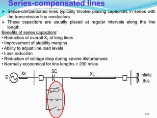
Series-compensated lines
E
Xs SCXL Infinte
Bus
Series-compensated lines typically involve placing capacitors in series with
the transmission line conductors.
These capacitors are usually placed at regular intervals along the line
length.
Benefits of series capacitors:
• Reduction of overall XL of long lines
• Improvement of stability margins
• Ability to adjust line load levels
• Loss reduction
• Reduction of voltage drop during severe disturbances
• Normally economical for line lengths > 200 miles
137
138.
Series-compensated lines
E
Xs SCXL Infinte
Bus
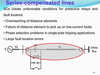
SCs create unfavorable conditions for protective relays and
fault locators:
• Overreaching of distance elements
• Failure of distance element to pick up on low-current faults
• Phase selection problems in single-pole tripping applications
• Large fault location errors
138
139.
Series-compensated lines
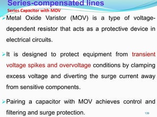
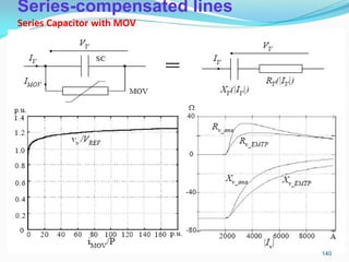
Series Capacitorwith MOV
Metal Oxide Varistor (MOV) is a type of voltage-
dependent resistor that acts as a protective device in
electrical circuits.
It is designed to protect equipment from transient
voltage spikes and overvoltage conditions by clamping
excess voltage and diverting the surge current away
from sensitive components.
Pairing a capacitor with MOV achieves control and
filtering and surge protection. 139
Series-compensated lines
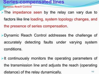
Dynamic ReachControl
The impedance seen by the relay can vary due to
factors like line loading, system topology changes, and
the presence of series compensation.
Dynamic Reach Control addresses the challenge of
accurately detecting faults under varying system
conditions.
It continuously monitors the operating parameters of
the transmission line and adjusts the reach (operating
distance) of the relay dynamically. 142
143.
Series-compensated lines
Dynamic ReachControl
143
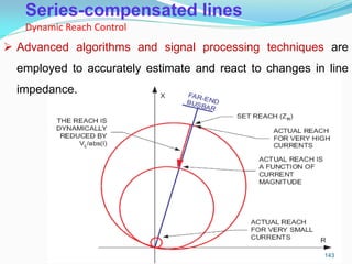
Advanced algorithms and signal processing techniques are
employed to accurately estimate and react to changes in line
impedance.
144.
Series-compensated lines
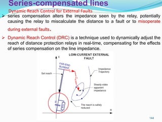
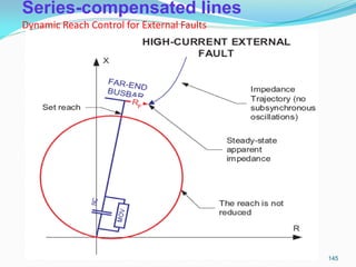
Dynamic ReachControl for External Faults
144
series compensation alters the impedance seen by the relay, potentially
causing the relay to miscalculate the distance to a fault or to misoperate
during external faults.
Dynamic Reach Control (DRC) is a technique used to dynamically adjust the
reach of distance protection relays in real-time, compensating for the effects
of series compensation on the line impedance.
Series-compensated lines
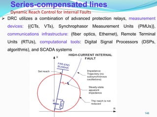
Dynamic ReachControl for Internal Faults
146
DRC utilizes a combination of advanced protection relays, measurement
devices: {(CTs, VTs), Synchrophasor Measurement Units (PMUs)},
communications infrastructure: (fiber optics, Ethernet), Remote Terminal
Units (RTUs), computational tools: Digital Signal Processors (DSPs,
algorithms), and SCADA systems
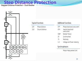
147.
Distance Protection LookingThrough a
Transformer
Phase distance elements can be set to see beyond
any 3-phase power transformer.
CTs & VTs may be located independently on different
sides of the transformer.
Given distance zone is defined by VT location (not
CTs).
Reach setting is in sec, and must take into account
location & ratios of VTs, CTs and voltage ratio of the
involved power transformer.
147
148.
Transformer Group Compensation
Thelocation of voltage transformers (VTs) and current
transformers (CTs) relative to power transformers can introduce
phase shift and magnitude changes in the signals they
measure.
These changes can affect the accuracy of distance relays,
which are critical for detecting and isolating faults in
transmission lines.
Power transformers inherently cause phase shifts between the
primary and secondary sides due to the winding configuration
and transformer design.
148
149.
Transformer Group Compensation
Phaseshift can distort the measurement of voltage and current
phasors at the secondary side of the transformer compared to
the primary side.
Distance relays, rely on accurate phase angle information to
determine the distance to a fault.
Transformers also cause a change in the magnitude of the
voltage and current signals due to transformation ratios and
impedance characteristics.
This change in magnitude can affect the sensitivity and
accuracy of distance relays in detecting fault conditions.
149
150.
Transformer Group Compensation
Dependingon location of VTs and CTs, distance relays need to compensate for the
phase shift and magnitude change caused by the power transformer. 150
Achieved by applying a correction factor to the phase angle measurements
obtained from VTs and CTs.
Which accounts for the known phase shift and Magnitude caused by the
transformer.
151.
Setting Rules
Transformer positivesequence impedance must be
included in reach setting only if transformer lies
between VTs and intended reach point.
Currents require compensation only if transformer
located between CTs and intended reach point.
Voltages require compensation only if transformer
located between VTs and intended reach point.
Compensation set based on transformer connection &
vector group as seen from CTs/VTs toward reach point.
151
152.
Distance Relay DesirableAttributes
Multiple reversible distance zones
Individual per-zone, per-element characteristic:
Dynamic voltage memory polarization
Various characteristics, including mho, quad, lenticular
Individual per-zone, per-element current supervision
Multi-input phase comparator:
additional ground directional supervision
dynamic reactance supervision
Transient overreach filtering/control
Phase shift & magnitude compensation for distance applications
with power transformers
152
153.
Distance Relay DesirableAttributes
For improved flexibility, it is desirable to have the
following parameters settable on a per zone basis:
Zero-sequence compensation
Mutual zero-sequence compensation
Maximum torque angle
Blinders
Directional angle
Comparator limit angles (for lenticular characteristic)
Overcurrent supervision
153
154.
Distance Relay DesirableAttributes
Additional functions
Overcurrent elements (phase, neutral, ground, directional,
negative sequence, etc.)
Breaker failure
Automatic reclosing (single & three-pole)
Sync check
Under/over voltage elements
Special functions
Power swing detection
Load encroachment
Pilot schemes
154

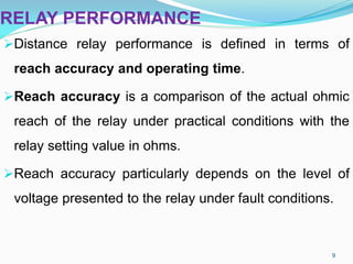
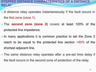
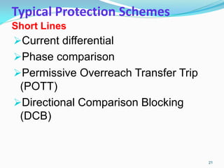
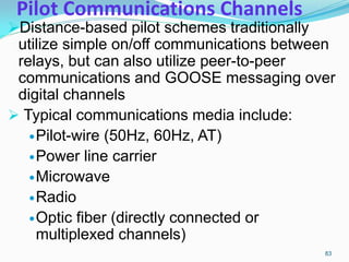
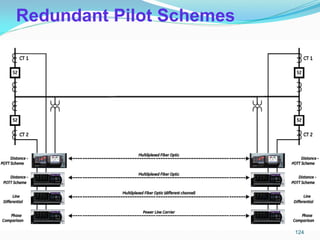
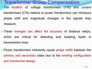
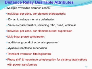
![Challenges in relay design
-0.5 0 0.5 1 1.5
-100
-80
-60
-40
-20
0
20
40
60
80
100
Voltage
[V]
-0.5 0 0.5 1 1.5
-3
-2
-1
0
1
2
3
4
5
Current
[A]
vA
vB vC
iA
iB
,iC
-0.5 0 0.5 1 1.5
-100
-50
0
50
100
Reactance
comparator
[V]
power cycles
SPOL
SOP
> In-phase = internal fault
> Out-of-phase = external
fault
43](https://image.slidesharecdn.com/distanceprotection-250324064702-733a37ab/85/Distance-Protection-in-power-system-pdf-43-320.jpg)
![-10 -5 0 5 10
-5
0
5
10
15
Reactance
[ohm]
Resistance [ohm]
18
22
26
30
34
42
44 Actual Fault
Location
Line
Impedance
Trajectory
(msec)
dynamic mho
zone extended
for high SIRs
Impedance locus may pass
below the origin of the Z-plane -
this would call for a time delay
to obtain stability 48](https://image.slidesharecdn.com/distanceprotection-250324064702-733a37ab/85/Distance-Protection-in-power-system-pdf-48-320.jpg)
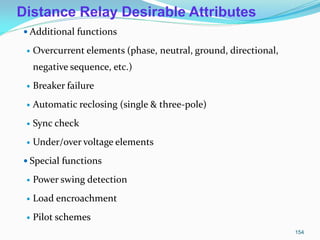
![0 5 10 15 20 25 30
0
10
20
30
40
50
60
70
80
90
100
Maximum
Rach
[%]
SIR
Actual maximum reach curves
Relay 1
Relay 3
Relay 2
Relay 4
56](https://image.slidesharecdn.com/distanceprotection-250324064702-733a37ab/85/Distance-Protection-in-power-system-pdf-56-320.jpg)


![protection of transmission lines[distance relay protection scheme]](https://cdn.slidesharecdn.com/ss_thumbnails/os-exe3-23-may2011-sr-i-776s21tr-lineprotection-120425095503-phpapp02-thumbnail.jpg?width=640&height=640&fit=bounds)


