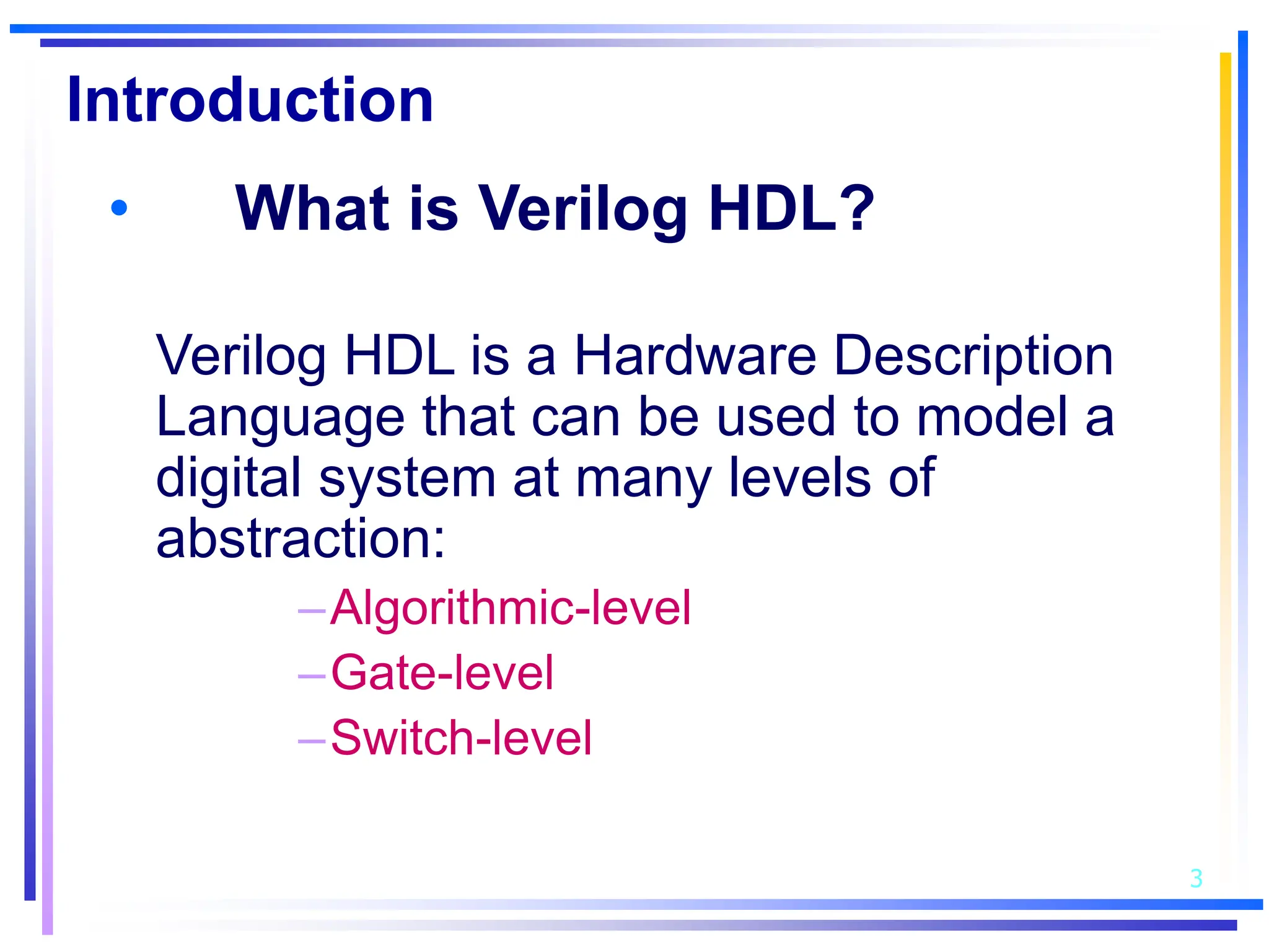
1. Verilog HDL is a hardware description language used to model digital systems at different levels of abstraction including algorithmic, gate, and behavioral levels.
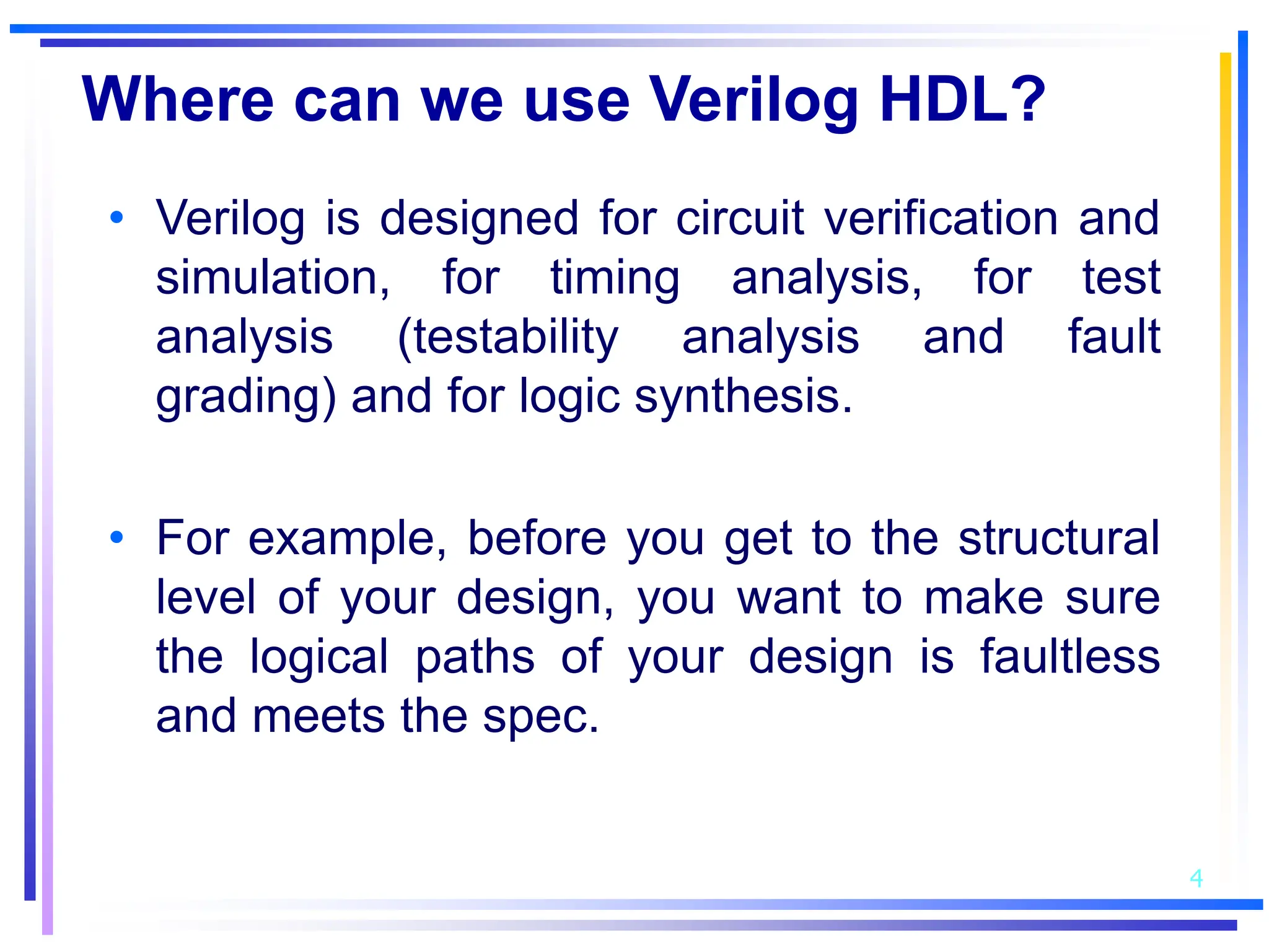
2. Verilog can be used for circuit verification, simulation, timing analysis, testability analysis, and logic synthesis. It allows modeling at the gate level using primitive gates and modules or at the behavioral level using procedural constructs.
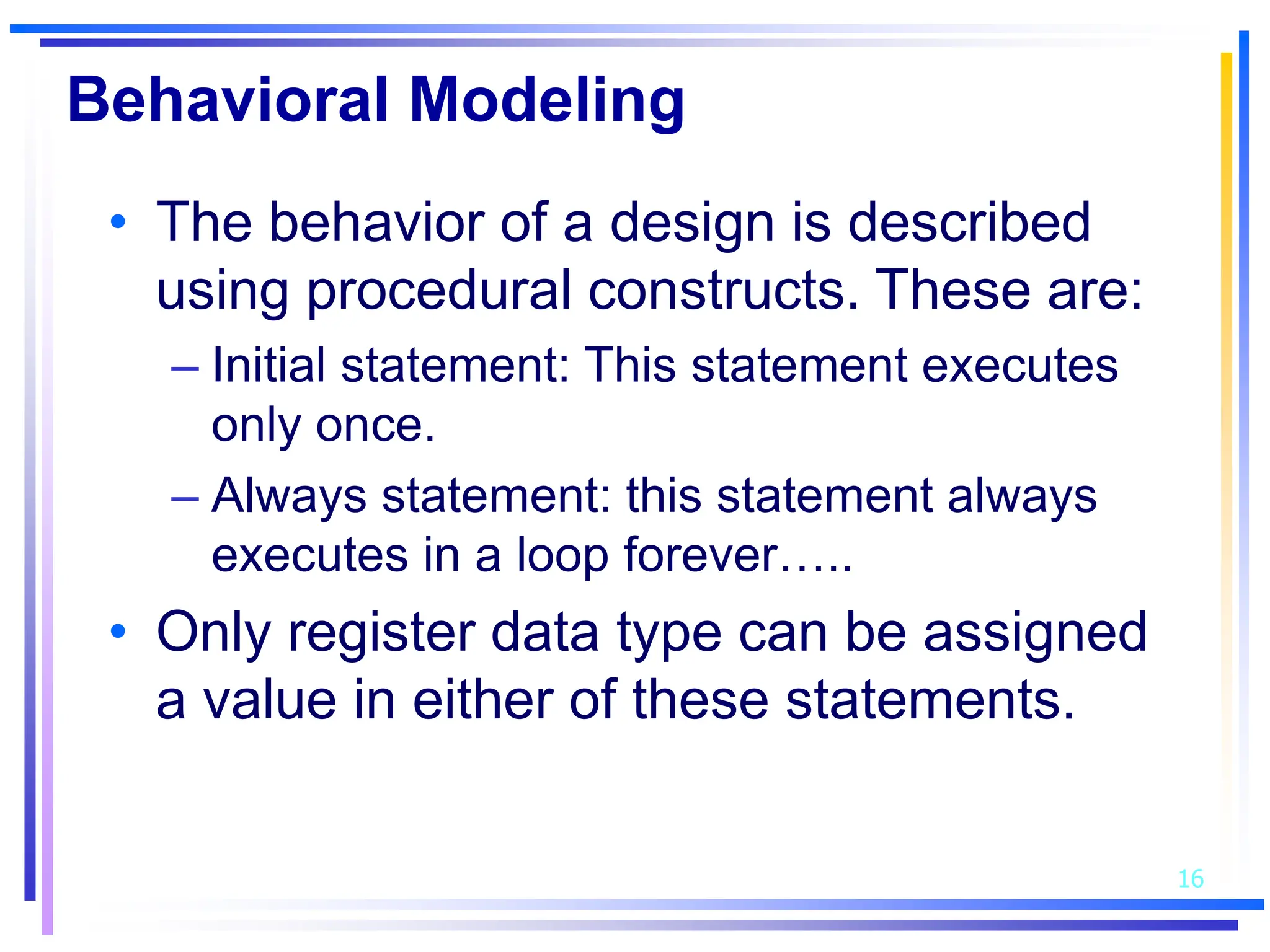
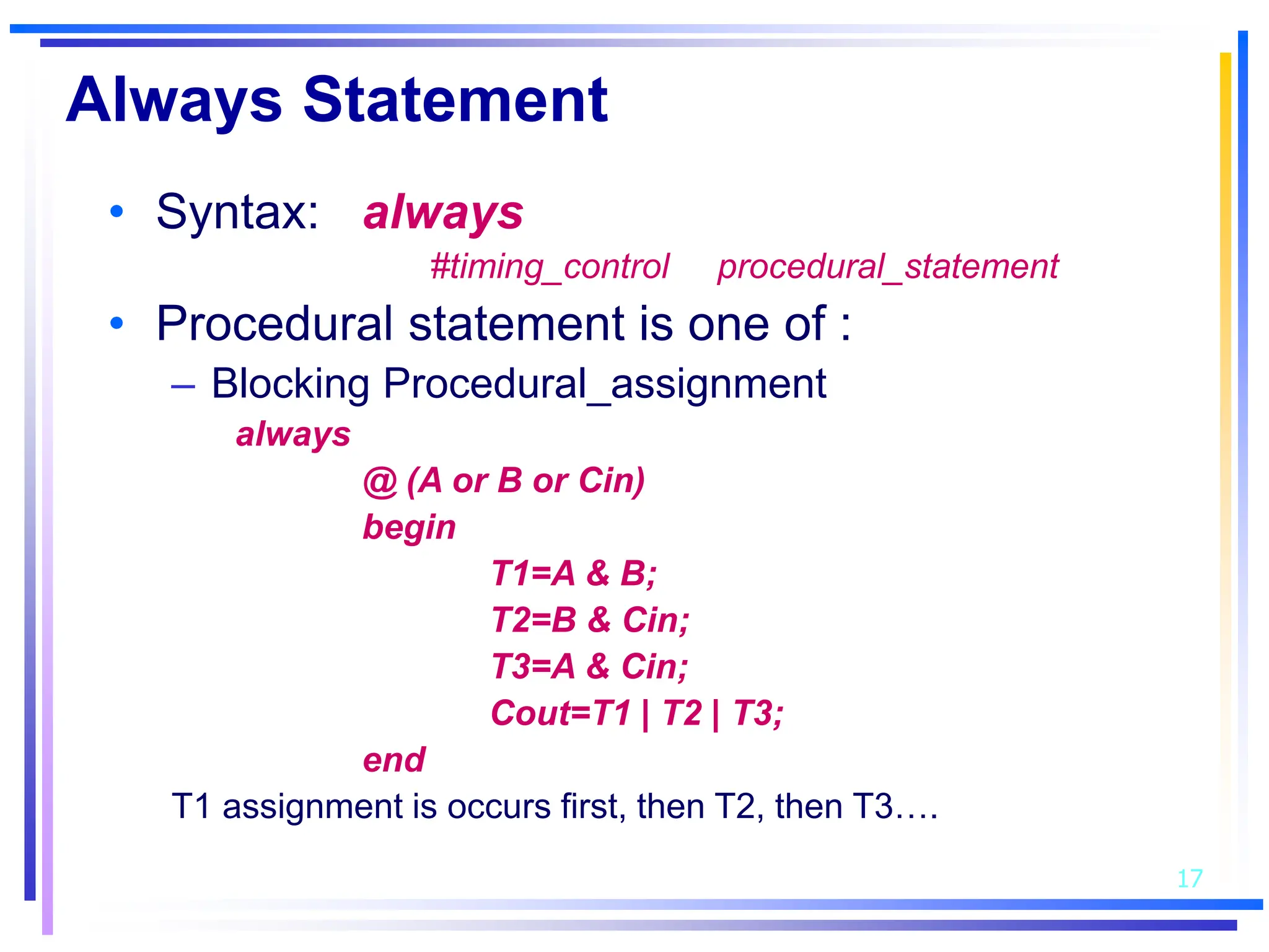
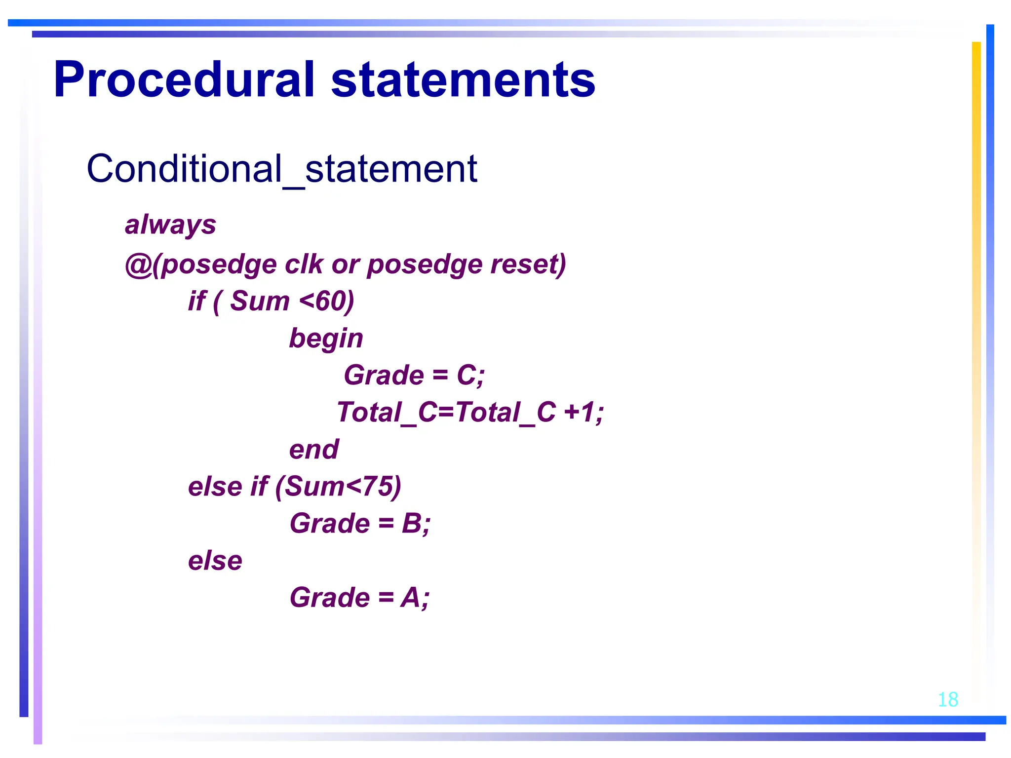
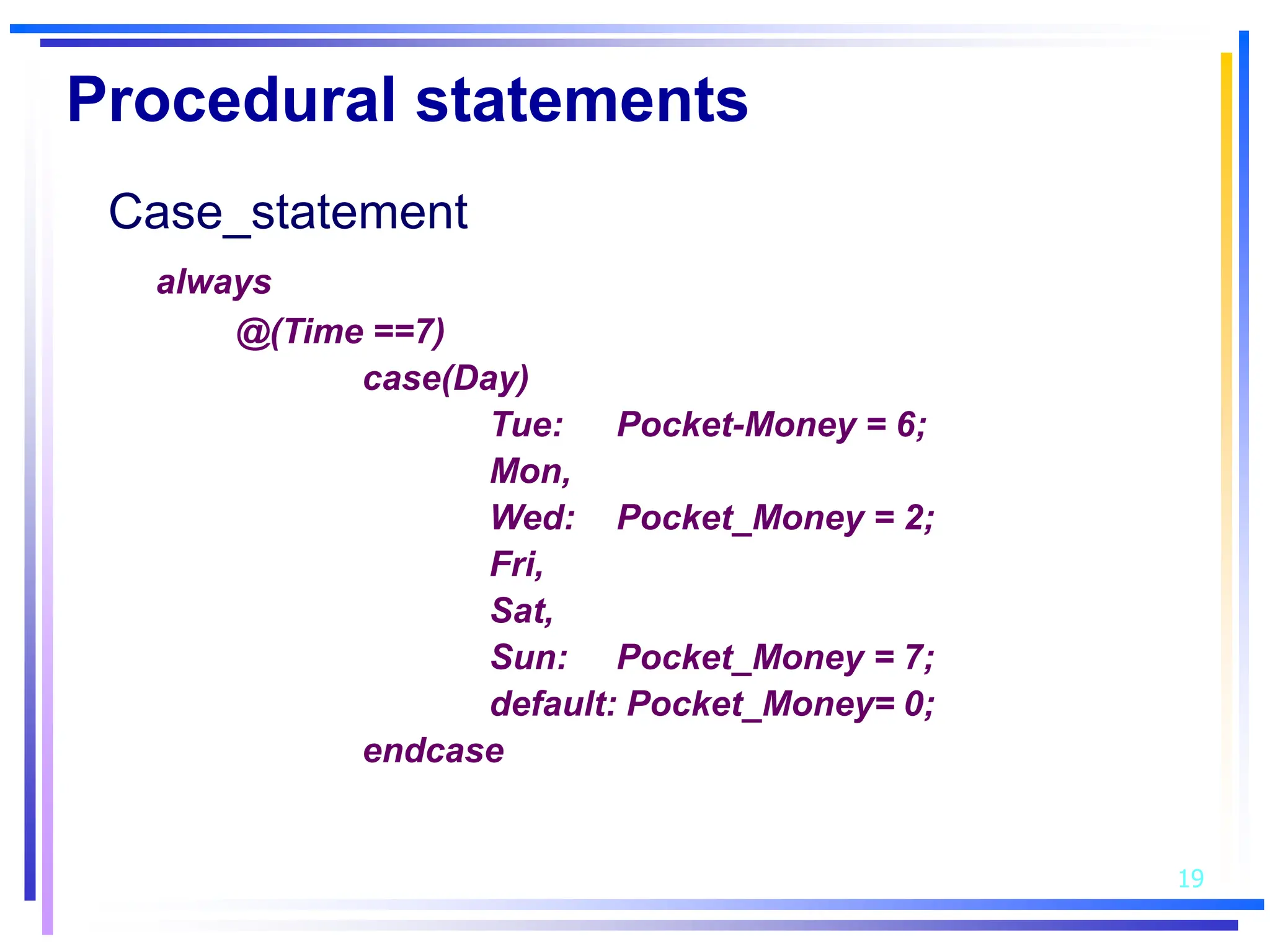
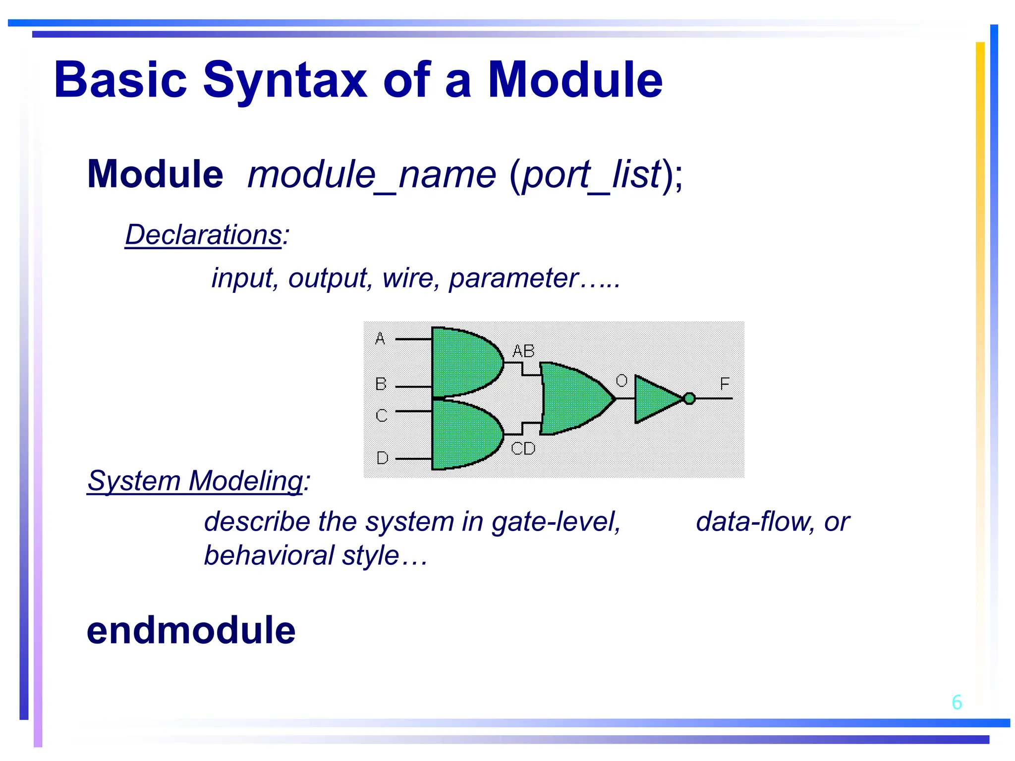
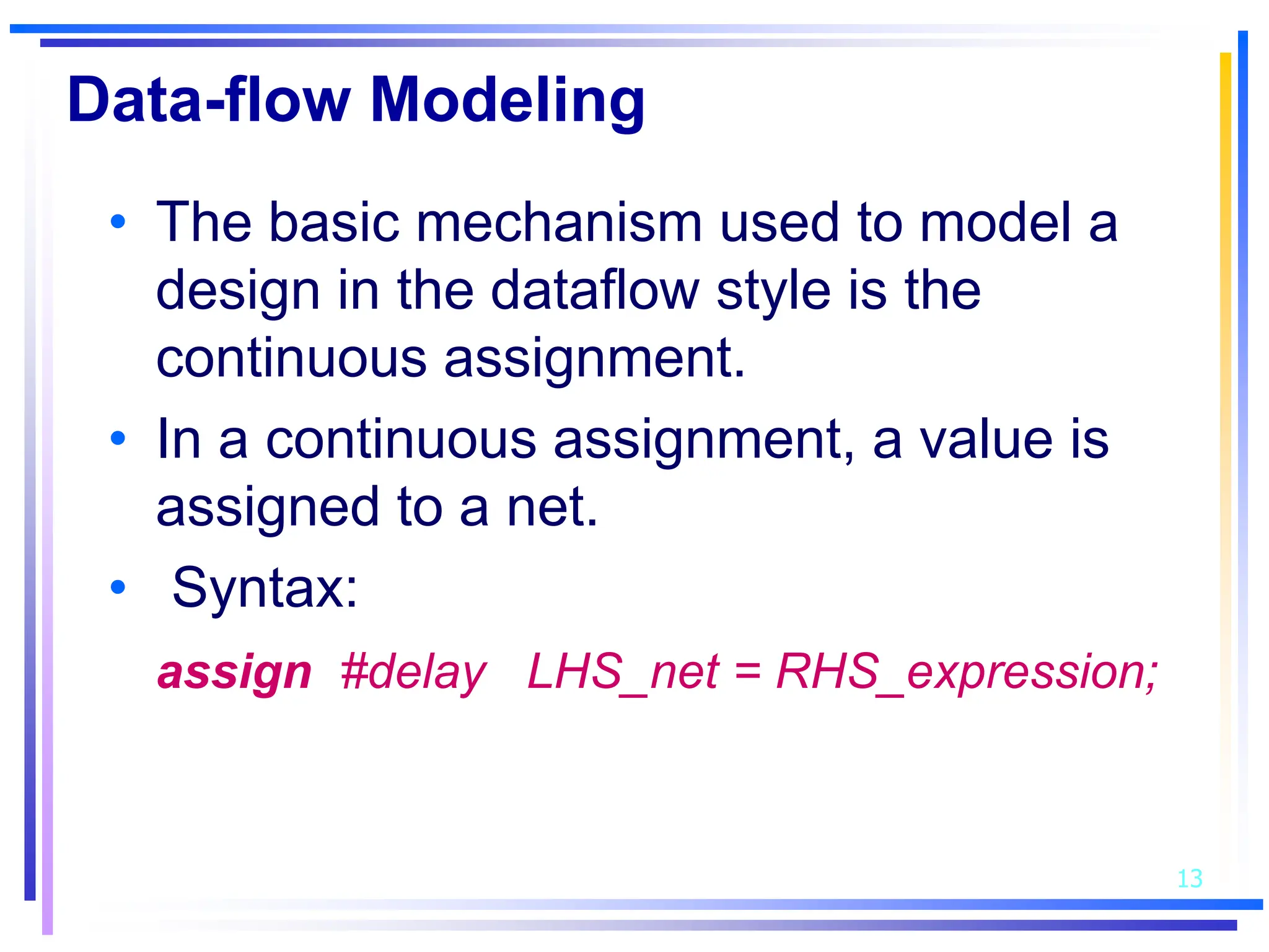
3. Basic Verilog constructs include modules to describe systems, continuous assignments for data flow modeling, primitive gates, always and initial blocks for behavioral modeling, and case and if-else statements to model conditional logic.
![12
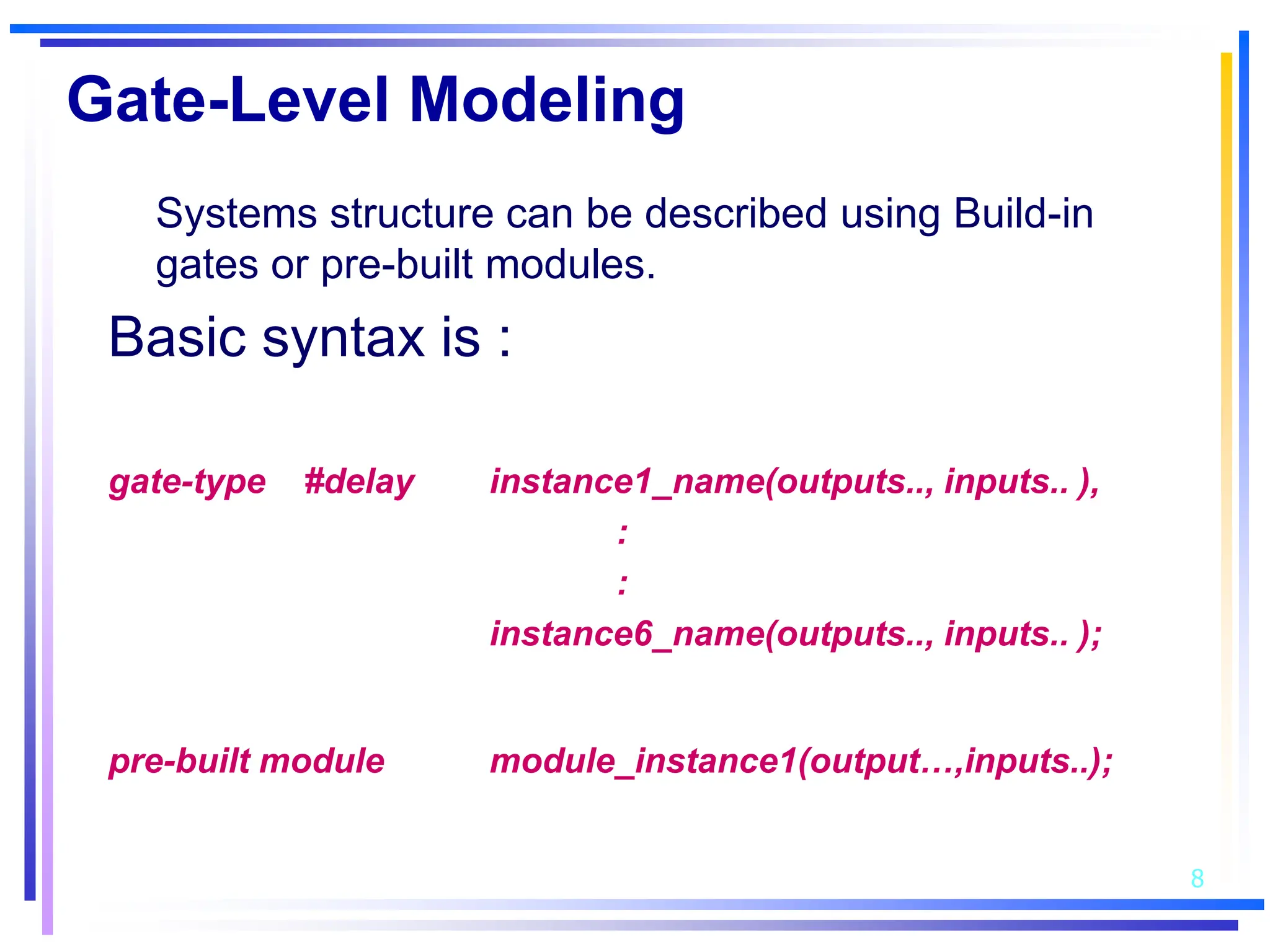
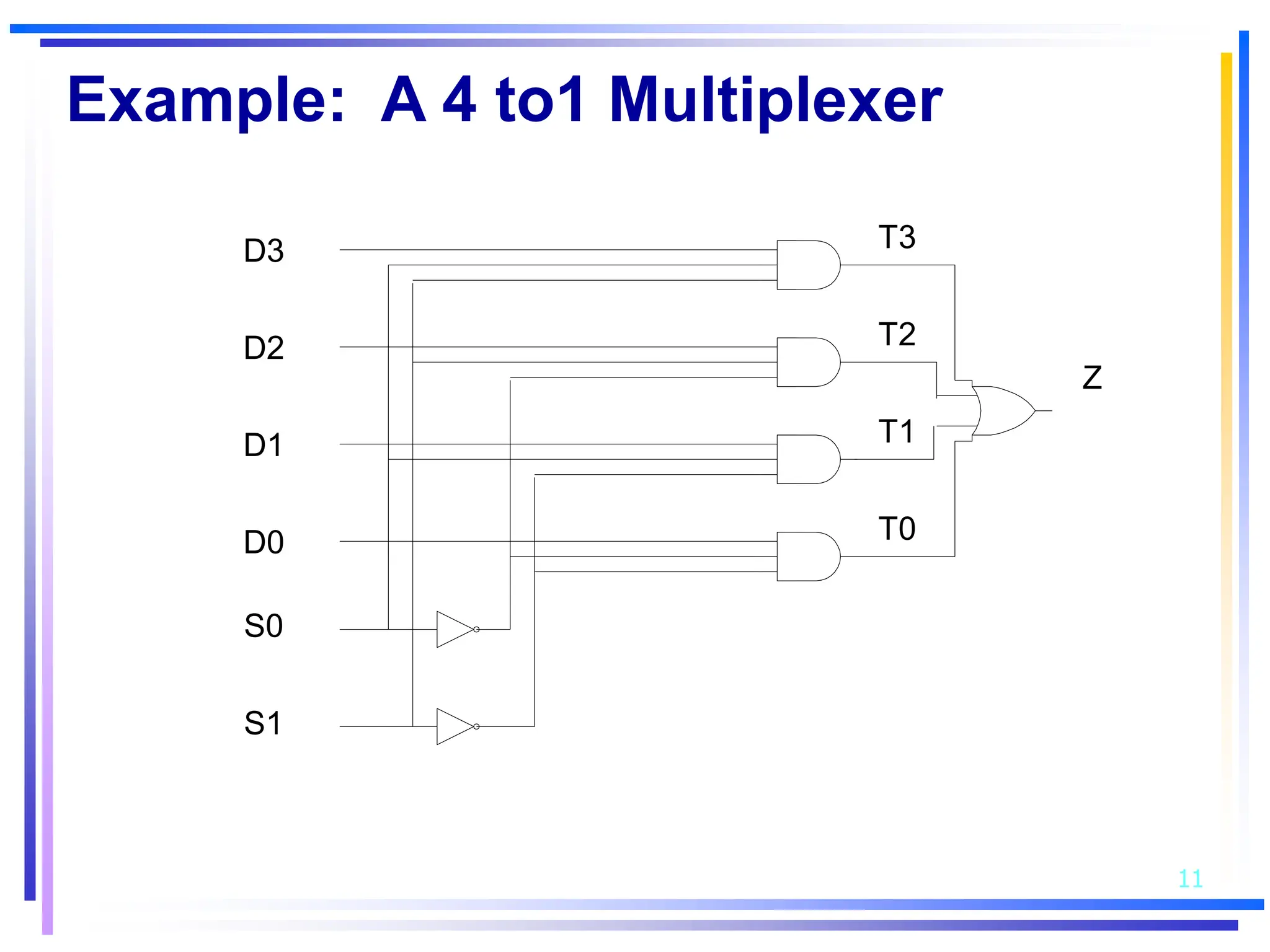
Simple Example
module Mux4_1 (Z, D,S);
output Z;
input [3:0] D;
input [1:0] S;
wire S0b, S1b, T0, T1, T2, T3;
not #5 inv0(S0b, S[0]),
inv1(S1b, S[1]);
and #10 and0(T0, D[0], S1b, S0b),
and1(T1, D[1], S1b, S[0]),
and2(T2, D[2], S[1], S0b),
and3(T3, D[3], S[0], S[1]);
or #10 or1(Z, T0,T1,T2,T3);
endmodule](https://image.slidesharecdn.com/veriloghdl-231010173639-488f25a2/75/VerilogHDL-ppt-12-2048.jpg)
![10/10/2023 Brigette Huang - Autumn 2002 14
Example: 2 to 4 Decoder
A
B
EN
Z[0]
Z[1]
Z[2]
Z[3]](https://image.slidesharecdn.com/veriloghdl-231010173639-488f25a2/75/VerilogHDL-ppt-14-2048.jpg)
![15
Example
module Decoder 2_4(A,B,EN,Z);
Input A,B,EN;
output [0:3] Z;
wire Ab, Bb;
assign #1 Ab=~A;
assign #1 Bb=~B;
assign #2 Z[0]=~(Ab & Bb & EN);
assign #2 Z[1]=~(Ab & B & EN);
assign #2 Z[2]=~(A & Bb & EN);
assign #2 Z[3]=~(A & B & EN);
endmodule](https://image.slidesharecdn.com/veriloghdl-231010173639-488f25a2/75/VerilogHDL-ppt-15-2048.jpg)